VALIDATION OF SERPENT FOR FUSION NEUTRONICS ANALYSIS AT JET
←
→
Page content transcription
If your browser does not render page correctly, please read the page content below
EPJ Web of Conferences 247, 18001 (2021)                                                               https://doi.org/10.1051/epjconf/202124718001
PHYSOR2020

             VALIDATION OF SERPENT FOR FUSION NEUTRONICS ANALYSIS
                                    AT JET

                  Andrej Žohar1,2 , Žiga Štancar1 , Paola Batistoni3,4 , Sean Conroy5 , Luka Snoj1,2 ,
                                          Igor Lengar1 and JET contributors6
                                 1
                                   Reactor Physics Department, Jožef Stefan Institute
                                        Jamova cesta 39, 1000 Ljubljana, Slovenia
                                   2
                                       University of Ljubljana, Faculty of Mathematics and Physics
                                               Jamova cesta 19, 1000 Ljubljana, Slovenia
                                                            3
                                                         Fusion Technical Unit
                                                Via E. Fermi 45, I-00044 Frascati, Italy
                                                     4
                                                         CCFE, Culham Science Center
                                                          Abingdon, OX14 3DB, UK
                               5
                                   VR, Department of Physics and Astronomy, Uppsala University
                                              Box 516, SE-75120 Uppsala, Sweden
                               6
                             See the author list of E. Joffrin et al. accepted for publication in
                      Nuclear Fusion Special issue 2019, https://doi.org/10.1088/1741-4326/ab2276

                               andrej.zohar@ijs.si, ziga.stancar@ijs.si, paola.batistoni@enea.it,
                               sean.conroy@physics.uu.se, luka.snoj@ijs.si, igor.lengar@ijs.si

                                                                  ABSTRACT

               Fusion neutronics analysis before and after experiments at JET is traditionally performed
               using Monte Carlo particle transport code Monte Carlo N-Particle. For redundancy and
               diversity reasons there is a need of an additional Monte Carlo code, such as Serpent 2,
               capable of fusion neutronics analysis. In order to validate the Serpent code for fusion
               applications a detailed model of JET was used. Neutron fluxes and reaction rates were
               calculated and compared for positions outside the tokamak vacuum vessel, in the vacuum
               vessel above the plasma and next to a limiter inside the vacuum vessel. For all detector
               positions with DD and DT neutron sources the difference between neutron fluxes calcu-
               lated with both Monte Carlo codes were within 2σ statistical uncertainty and for most
               positions (more than 90 % of all studied positions) even within 1σ uncertainty. Fusion
               neutronics analysis in the JET tokamak with Serpent took on average 10 % longer but
               this can be improved by changing the threshold value for determination of the transport
               method used. With the work presented in this paper the Serpent Monte Carlo code was
               validated to be a viable alternative to MCNP for fusion neutronics analysis for the JET
               tokamak.
         KEYWORDS: Neutron transport, MCNP, Serpent, JET

  © The Authors, published by EDP Sciences. This is an open access article distributed under the terms of the Creative Commons Attribution License 4.0
  (http://creativecommons.org/licenses/by/4.0/).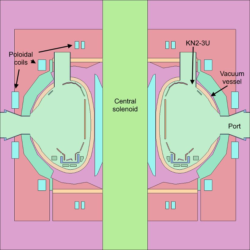
EPJ Web of Conferences 247, 18001 (2021)                                         https://doi.org/10.1051/epjconf/202124718001
PHYSOR2020

                                               1. INTRODUCTION

         Fusion neutronics analysis performed before and after experiments at JET are commonly supported
         by neutron transport calculations with the Monte Carlo particle transport code Monte Carlo N-
         Particle (MCNP)[1]. For fusion devices under design or construction, e.g., ITER and DEMO, the
         neutronics analysis for design and licensing is also performed by using MCNP. Complex Monte
         Carlo models are needed to obtain accurate results for verification of experiments and analysis of
         proposed designs. For the JET tokamak the current MCNP model has approximatly 4 000 cells
         and surfaces while the reference model for ITER (C-Model) has approximately 100 000 cells and
         surfaces [2].

         MCNP is a neutron transport code of US origin distributed through Radiation Safety Information
         Computational Centre. Its distribution is controlled, limited and subjected to US regulation. For
         this reason there is a need of an additional Monte Carlo code capable of fusion neutronics analysis
         for redundancy and diversity. Monte Carlo code Serpent 2 was first developed for nuclear analysis
         in fission reactors and burnup calculations and is under consideration as an alternative to MCNP
         for fusion neutronic analysis as it recently received several enhancements (coupled neutron-photon
         transport, variance reduction methods, etc.) that make it viable for use in fusion neutronics analysis
         and is easily obtainable through OECD/NEA [3].

         The validation of Serpent for fusion neutronics analysis has been divided into two steps. In the
         first step the code validation was performed on a representative simplified model of a fusion toka-
         mak reactor to study the effects of material cross sections on neutron transport and effects of
         neutron transport parameters (e.g. mean distance for the collision flux estimator, threshold for
         delta-tracking, etc.) and source definition on results. The results of the performed analysis are
         presented in [4]. In the second step, presented in this paper, the code was validated on a detailed
         model of the tokamak JET.

         The paper is organized as follows. In the first section the detailed MCNP model of the JET tokamak
         is presented and the process of converting it to Serpent. Second section presents the process of
         constructing a realistic plasma neutron source in Serpent on the basis of the neutron source used
         with MCNP. The last part of the paper presents the comparison of results between MCNP and
         Serpent at different in-vessel and ex-vessel detector positions for validation of Serpent for fusion
         neutronics analysis. An analysis of the transport parameter dt in Serpent, defining the threshold
         for delta-tracking transport method, was also performed.

                                                   2. SERPENT 2

         The Serpent code, released in 2009, was first developed for nuclear analysis in fission reactors and
         burnup calculations. The current version, Serpent 2, has received several enhancements that make
         it viable for Monte Carlo calculations beyond fission reactors. Serpent 2 now supports coupled
         neutron-photon transport, variance reduction methods, direct equivalents to most of the surface
         types contained in MCNP, cell and mesh tallies, ENDF reaction rate tally multipliers, custom
         response functions, etc. [5].

         A significant difference between MCNP and Serpent is in the implementation of particle transport.
         MCNP uses the surface-to-surface tracking method for particle transport over cell and material

                                                           2
EPJ Web of Conferences 247, 18001 (2021) https://doi.org/10.1051/epjconf/202124718001
PHYSOR2020
boundaries while Serpent uses a combination of surface-to-surface tracking method and Woodcock
delta tracking method [4,6]. The Woodcock delta tracking method allows for faster transport of
particles in complex geometries by homogenizing the material total cross sections in such a way,
that the sampled path lengths are valid over the entire geometry. This is achieved with the use of a
majorant cross section for path length determination. The majorant cross section is the highest total
cross section in the entire simulated model. This allows the random walk of particles to continue
across material boundaries thus speeding up the particle random walk in complex geometries.
However, the method also has disadvantages for fusion applications. Due to characteristics of
the method the track length estimator cannot be used for calculation of fluxes and a less efficient
collision flux estimator is used to obtain results. In vacuum regions (common in fusion models)
the collision flux estimator always yields a zero result. To overcome this disadvantages Serpent
uses a combination of both methods for particle transport and the threshold value that expresses
the ratio between material cross section and majorant cross section, is used for determination of
the tracking method.
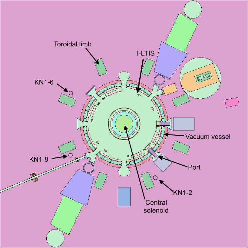
2.1. JET Monte Carlo model
The majority of neutronics analysis performed before and after experiments at JET is performed
using MCNP. Due to this a detailed model of the tokamak structure and surrounding diagnostic
equipment already exists. The model is composed of around 4 000 cells and surfaces and has
been validated on several different experiments performed in the past. The model is depicted in
Fig.1. As Serpent has direct equivalents to most of the MCNP surfaces the model was rewritten
to Serpent. This was achieved with an existing script for conversion of MCNP models to Serpent
which was tested with a simplified tokamak model [4]. It was ensured no errors occurred in the
model by ensuring no cell overlapped another cell and that during the computation neutrons were
not lost due to errors in geometry. The position of cells in the model was verified by plotting the
Serpent model geometry and comparing it to MCNP geometry plots.
(a) (b)
Figure 1: Cross sectional view of the JET tokamak model. The horizontal section is
presented in (a) and the vertical section is presented in (b).
3EPJ Web of Conferences 247, 18001 (2021) https://doi.org/10.1051/epjconf/202124718001
PHYSOR2020
2.2. Neutron source
Neutron analysis for support of JET experiments is performed with a D shaped neutron source
modelled on basis of several discharges at JET. The position and shape of the neutron source is
presented in Fig.2. The highest emission of neutrons is in the centre of the plasma and decreasing
towards the edge of plasma. The neutron source in MCNP is defined as a combination of toroidal
rings in vertical cross section with different probability of neutron emission but uniform distribu-
tion in the toroidal angle and isotropic distribution in the angle of neutron birth. The neutron energy
is sampled from a Gaussian distribution with mean energies of 2.5 MeV in deuterium-deuterium
plasma (DD) and 14.1 MeV in deuterium-tritium plasma (DT). The source definition in MCNP
was rewritten to Serpent. At the time of rewriting the neutron source Serpent did not have the ca-
pability to sample neutrons over cylindrical geometry. Due to this the neutron source from MCNP
was rewritten as a user defined source in Serpent. The constructed neutron source was validated
on a simplified tokamak model [4].
Figure 2: Sectional view of a realistic D shaped neutron source used for comparison
between MCNP and Serpent. The highest neutron emission is in the centre of the plasma
(yellow region) and is decreasing towards the plasma edge (blue regions).
3. RESULTS OF VALIDATION
For the computations it was ensured that the same material isotopic composition, the same nu-
clear data library, namely FENDL-3.1d [7], and the same neutron source was used in both Monte
Carlo codes. The neutron fluxes were calculated in the positions of three fission chambers called
KN1 located outside the vacuum vessel next to the transformer limbs (Fig.1), in four indium foils
located in irradiation ends, called KN2-3U, located above plasma on the inside of the vacuum
vessel commonly used for neutron activation measurements (Fig.1) and in a long term irradiation
station called I-LTIS located inside the vacuum vessel next to a limiter (Fig.1). For the indium
foils located in the KN2-3U position the reaction rates were also calculated as the activation of
foils is used for absolute calibration of JET neutron detectors, i.e. the KN1 fission chambers. The
results of comparison between Serpent and MCNP calculated neutron fluxes and reaction rates are
4EPJ Web of Conferences 247, 18001 (2021) https://doi.org/10.1051/epjconf/202124718001
PHYSOR2020
presented in Fig.3 and Fig.4.
For the KN1 fission chamber positions the calculated neutron fluxes show good agreement as
the difference between Serpent and MCNP is less than 0.3 % for DD and DT plasmas while the
statistical uncertainty of MCNP and Serpent is 0.4 %. The difference in the calculated neutron
fluxes and reaction rates for Indium-115 between Serpent and MCNP for KN2-3U position is
larger for DD plasma at around 0.8 % while for DT plasma the difference is less than 0.2 %. The
uncertainties of calculated neutron fluxes with MCNP and Serpent for KN1 and KN2-3U were
0.8 % while uncertainties of reaction rates were 1.5 %. The highest difference between MCNP
and Serpent can be observed for the calculated neutron fluxes in the long-term irradiation station
I-LTIS. The irradiation station consists of 30 positions for samples with diameter of 1.8 cm and
thickness of 2 mm. The statistical uncertainty of the calculated neutron fluxes with MCNP is
0.6% for all irradiation locations and the variation of neutron fluxes between positions is around
2% despite close clustering of positions. For neutron fluxes calculated with Serpent the statistical
uncertainties are around 5 % and the variation of neutron fluxes between positions is around 6 %.
The current results show good agreement between MCNP and Serpent for calculation of neutron
fluxes in detector positions located outside the vacuum vessel and close to plasma, but there are
still observable differences for small detector positions close to the plasma and inside the vacuum
vessel.
An important parameter for viability of Serpent for fusion neutronics is also the computational
time. For all studied cases the computational time of Serpent was slower compared to MCNP by
around 10 %.
0.08
Relative difference (Serpent / MCNP)
0.06
0.04
0.02
0
−0.02
−0.04
−0.06
−0.08
−0.1
−0.12
−0.14
KN1−8
KN1−2
KN1−6
KN2−3U−1
KN2−3U−2
KN2−3U−3
KN2−3U−4
KN2−3U−1−RR
KN2−3U−2−RR
KN2−3U−3−RR
KN2−3U−4−RR
I−LTIS−1
I−LTIS−2
I−LTIS−3
I−LTIS−4
I−LTIS−5
I−LTIS−6
I−LTIS−7
I−LTIS−8
I−LTIS−9
I−LTIS−10
I−LTIS−11
I−LTIS−12
I−LTIS−13
I−LTIS−14
I−LTIS−15
I−LTIS−16
I−LTIS−17
I−LTIS−18
I−LTIS−19
I−LTIS−20
I−LTIS−21
I−LTIS−22
I−LTIS−23
I−LTIS−24
I−LTIS−25
I−LTIS−26
I−LTIS−27
I−LTIS−28
I−LTIS−29
I−LTIS−30
Detector
Figure 3: Relative difference of neutron fluxes between Serpent and MCNP for all detector
positions and reaction rates in a DD plasma. The 1σ uncertainty of MCNP is presented with
the green bars while the 1σ uncertainty of Serpent is presented with lines.
5EPJ Web of Conferences 247, 18001 (2021) https://doi.org/10.1051/epjconf/202124718001
PHYSOR2020
0.2
Relative difference (Serpent / MCNP)
0.15
0.1
0.05
0
−0.05
−0.1
−0.15
KN1−8
KN1−2
KN1−6
KN2−3U−1
KN2−3U−2
KN2−3U−3
KN2−3U−4
KN2−3U−1−RR
KN2−3U−2−RR
KN2−3U−3−RR
KN2−3U−4−RR
I−LTIS−1
I−LTIS−2
I−LTIS−3
I−LTIS−4
I−LTIS−5
I−LTIS−6
I−LTIS−7
I−LTIS−8
I−LTIS−9
I−LTIS−10
I−LTIS−11
I−LTIS−12
I−LTIS−13
I−LTIS−14
I−LTIS−15
I−LTIS−16
I−LTIS−17
I−LTIS−18
I−LTIS−19
I−LTIS−20
I−LTIS−21
I−LTIS−22
I−LTIS−23
I−LTIS−24
I−LTIS−25
I−LTIS−26
I−LTIS−27
I−LTIS−28
I−LTIS−29
I−LTIS−30
Detector
Figure 4: Relative difference of neutron fluxes between Serpent and MCNP for all detector
position and reaction rates in DT plasma. The 1σ uncertainty of MCNP is presented with
the green bars while the 1σ uncertainty of Serpent is presented with lines.
3.1. Analysis of dt parameter
As already stated in the paper Serpent uses two different methods for neutron transport, namely
surface-to-surface and delta tracking method. The parameter determining which method is used
for neutron transport is called dt. The parameter is one minus the ratio of the total cross section
Σ
in the material the particle is located in and the majorant (dt = 1 − ΣT,i M
), or in other words the
parameter dt represents the size of the interval for usage of the delta tracking method. By default
the value of the parameter is set at 0.9, i.e. delta tracking is used if the ratio between the total cross
section and the majorant is above 0.1. If the value of parameter dt is set at 0 then only surface-
to-surface tracking method is used and if the value of parameter is 1 only delta tracking method
is used. All previously presented results used the default threshold value for determination of the
transport method.
To analyse the effectiveness of delta tracking method for fusion neutronics analysis the parameter
dt was varied from 0 to 0.9, i.e. from only surface-to-surface tracking method to default parameter.
For all values of parameter dt the calculated neutron fluxes and reaction rates for all positions were
within statistical uncertainty compared to MCNP thus proving that the particle transport method
does not affect results. However, the calculation times differed depending on the value of parameter
dt. The relative difference in computation time between Serpent and MCNP for different values
of parameter dt are presented in Fig.5. The results presented are for DD plasma only but results
for a DT plasma are similar.
6EPJ Web of Conferences 247, 18001 (2021) https://doi.org/10.1051/epjconf/202124718001
PHYSOR2020
The results show that computational time of Serpent is similar to MCNP for only surface-to-surface
tracking method. With the default value of parameter dt the computational time of Serpent is
slower by 10 % compared to MCNP. This is due to the use of delta tracking method in majority of
materials. By the lowering of the size of the interval the number of materials and regions in which
surface-to-surface tracking method is used increases. As there are many and big regions in the JET
tokamak model with low total cross section (e.g. air surrounding the tokamak) the particle transport
is faster with the surface-to-surface tracking method. This is opposite to situation in fission reactors
where the delta tracking method can speed up computation time compared to MCNP. Due to this
it is recommended to lower the threshold value of parameter dt for fusion neutronics analysis to
obtain similar computing time in Serpent and MCNP.
1.1
1.09
Relative difference in
1.08
computational time
(Serpent / MCNP)
1.07
1.06
1.05
1.04
1.03
1.02
1.01
1
0 0.1 0.2 0.3 0.4 0.5 0.6 0.7 0.8 0.9
dt threshold value
Figure 5: Relative difference in computational time of Serpent to MCNP for different
threshold values of parameter dt for determination of used transport method. The results
presented are only for a DD plasma but the results are similar for a DT plasma.
4. CONCLUSIONS
In this paper an analysis of the Serpent Monte Carlo code was performed for its use in fusion
neutronics analysis for the JET tokamak. During the analysis it was ensured: the same tokamak
model, the same material compositions, the same evaluated nuclear data libraries and the same
neutron sources in Serpent and the reference code MCNP were used. A D shaped neutron source in
Serpent was modelled to be representative of high performance discharges at JET. It was rewritten
to Serpent as a user defined source as at the time of the analysis Serpent did not support the same
source definitions as MCNP.
The comparison of calculated neutron fluxes between MCNP and Serpent was performed for three
fission chamber positions called KN1 located outside the tokamak vacuum vessel, in activation
system named KN2-3U on top of plasma in the vacuum vessel structure and long term irradiation
station I-LTIS next to a limiter inside the vacuum vessel. For all detector positions with the DD and
7EPJ Web of Conferences 247, 18001 (2021) https://doi.org/10.1051/epjconf/202124718001
PHYSOR2020
DT neutron sources the difference between neutron fluxes calculated with MCNP and Serpent were
within 2σ Monte Carlo statistical uncertainty and for most positions even within 1σ uncertainty.
For reaction rates in In-115 at the position KN2-3U the calculated values between Serpent and
MCNP are within 1σ statistical uncertainty. There are significant differences between Serpent and
MCNP for fusion neutronics analysis in small regions, like the sample positions in I-LTIS, where
Serpent has a lower efficiency thus producing results with higher statistical uncertainty compared
to MCNP for the same number of simulated particles.
Serpent uses two different methods for neutron transport - surface-to-surface and delta tracking.
By default the surface-to-surface tracking method is only used when the ratio between the material
total cross section and the majorant cross section is below 0.1. For fusion neutronics analysis in
the JET tokamak this threshold value needs to be increased with the parameter dt as this speeds
up the computation to the same computing time as MCNP.
With the presented results the Serpent Monte Carlo code was validated to be a viable alternative to
MCNP for fusion neutronics analysis at the JET tokamak.
ACKNOWLEDGEMENTS
This work has been carried out within the framework of the EUROfusion Consortium and has
received funding from the Euratom research and training programme 2014-2018 and 2019-2020
under grant agreement No 633053. The views and opinions expressed herein do not necessarily
reflect those of the European Commission.
The work was supported by the Slovenian Ministry of Education, Science and Sport (projects
codes: P2-0073 Reactor Physics; P2-0405 Fusion technologies; 1000-17-0106-6 - Training of
young researchers).
REFERENCES
[1] C. J. Werner. MCNP Users Manual - Code Version 6.2. Los Alamos National Laboratory,
report LA-UR-17-29981 (2017).
[2] D. Leichtle et al. “The ITER tokamak neutronics reference model C-Model.” Fusion Engi-
neering and Design, volume 136, pp. 742 – 746 (2018). Special Issue: Proceedings of the
13th International Symposium on Fusion Nuclear Technology (ISFNT-13).
[3] J. Leppänen et al. “The Serpent Monte Carlo code: Status, development and applications in
2013.” Annals of Nuclear Energy, volume 82, pp. 142 – 150 (2015).
[4] A. Žohar, I. Lengar, and L. Snoj. “Comparison of MCNP and Serpent for Fusion Transport
Simulations.” In Proceedings, 28th International Conference Nuclear Energy for New Europe
- NENE 2019 (2019).
[5] A. Turner et al. “Applications of Serpent 2 Monte Carlo Code to ITER Neutronics Analysis.”
Fusion Science and Technology, volume 74(4), pp. 315–320 (2018).
[6] J. Leppänen. “Performance of Woodcock delta-tracking in lattice physics applications using
the Serpent Monte Carlo reactor physics burnup calculation code.” Annals of Nuclear Energy,
volume 37(5), pp. 715 – 722 (2010).
[7] A. Koning and A. Trkov. “FENDL-3.1d: Fusion Evaluated Nuclear Data Library Ver.3.1d.”
(2018). URL https://www-nds.iaea.org/fendl/.
8You can also read