SAS Fitting Kit Manual - RALLY CAR - Appendix 5.1 - SAS Tracker Installation Manual - Arctic Rally Finland
←
→
Page content transcription
If your browser does not render page correctly, please read the page content below
Appendix 5.1 - SAS Tracker Installation Manual
                                                     P a g e |1

       SAS Fitting Kit Manual – RALLY CAR

SAS Fitting Kit Manual – RALLY CAR               Version 1.1

#ArcticRallyFinland                  71
P a g e |2

   Welcome
   This manual is provided as a guide for the installation of the WRC Tracking System Kit, for competition
   vehicles only. Care should be taken when considering the location of components with regard to
   electrical cabling and fire suppression systems already installed in the vehicle. Please check always
   that the components of your kit are as requested.

   Table of Contents
   1. Tracking Unit Kit Components ........................................................... 3

   2. Power Supply.................................................................................... 3

   3. Connection Diagram ......................................................................... 3
   4. Tracking Unit Dimensions ................................................................. 4
   5. Tracking Unit Mounting ..................................................................... 5
   6. Antenna Installation .......................................................................... 6

   6.1 External Antenna Installation ............................................................ 7

   6.2 Internal Antenna Installation ............................................................. 8

   7. Contact ............................................................................................. 8

   SAS Fitting Kit Manual – RALLY CAR                                                                   Version 1.1

#ArcticRallyFinland                                                72
P a g e |3
1. Tracking Unit Kit Components & Steps
The WRC Tracking System Kit includes:
WRC Tracking Installation and Fitting Kit
Instruction Sheet;
3-in-1 antenna with leads;
Internal radio antenna with lead;
6 – 24v wiring loom with plug;
Mount, to be bolted to tunnel;
Adjustable mount connector/knuckle.
(Contents may differ slightly to image shown)
WRC tracking system fitment steps:
1. Mount WRC tracker;
2. Fit external & internal antennas, running leads to the WRC tracker;
3. Fit wiring loom, ensuring that a solid 9 to 28 volts is supplied;
4. Connect all antenna connections, make sure they are tight using an 8mm spanner;
5. Apply power.
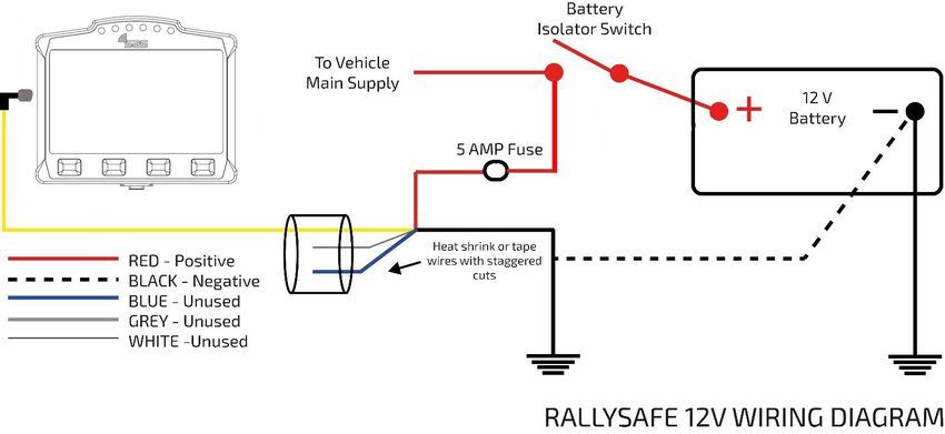
2. Power Supply
WRC tracking system requires a reliable power supply from 9 to 28 volts DC. We recommend a 5 amp
(Max) blade type or similar quality fuse is used at the battery supply end of the WRC tracking system
power lead.
Zero volts or battery negative can be picked up at any suitable earthing point providing the isolation
switch does not switch the negative side of the battery.
The WRC tracking system unit has an internal battery that is kept charged via the car’s power supply. It
acts as a reserve supply to power the unit in the case of an accident where a car’s power supply is
interrupted (e.g. car battery smashed or dislodged).
Note: The tracking device should only be powered once it is placed in its final position in the
vehicle; this ensures accelerometers are calibrated correctly.
SAS Fitting Kit Manual – RALLY CAR Version 1.1
#ArcticRallyFinland 73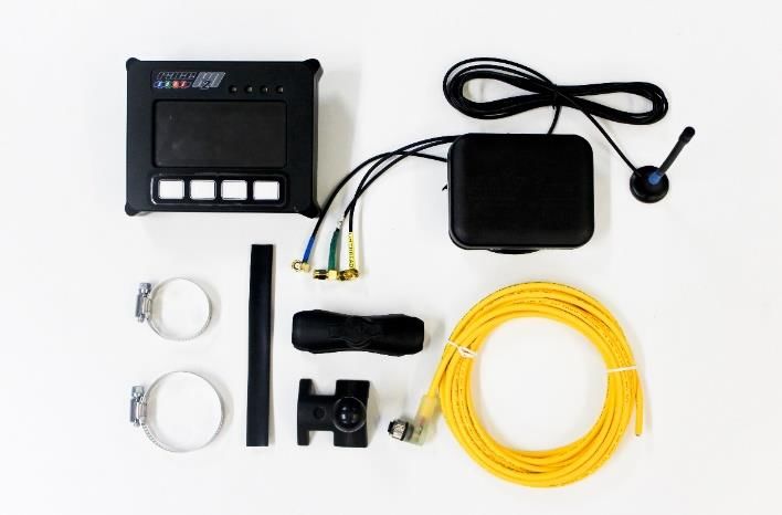
P a g e |4

   3. Connection Diagram
   The 6-24v wiring loom, includes five wires. The white blue and grey wires must be stagger cut and heat
   shrinked or taped back so they cannot short to ground or to each other. Red and black are used as
   follows:

   During installation, the wiring loom should be routed away from the engine compartment, Ignition or
   Alternator wiring.

   300 mm of Power Supply Wiring Loom is required to be available for connection to the WRC Tracker
   Unit at the mounted position.

   SAS Fitting Kit Manual – RALLY CAR                                                      Version 1.1

#ArcticRallyFinland                                       74
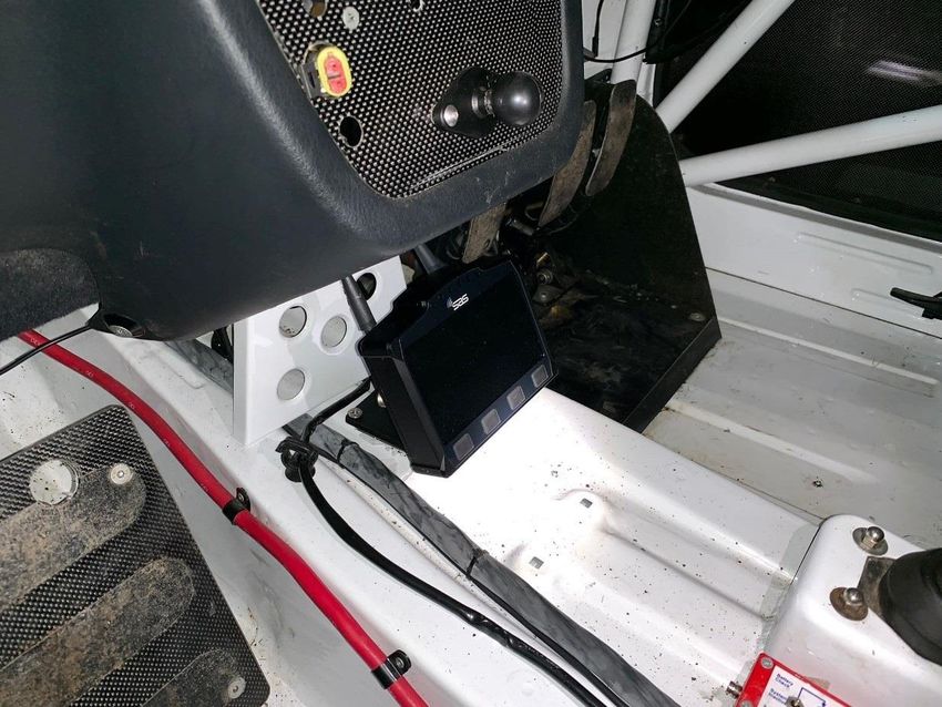
P a g e |5

  4. Tracking Unit Dimensions

  5. Tracking Unit Mounting
  The preferred location and mounting for the WRC tracking system unit is a RAM style 50mm x 75mm
  flat base with ball, bolted through the tunnel with four M6 Bolts.

  It should be in a central, protected location on the central tunnel in front of the seats and both easily
  visible and accessible by both the driver and co-driver/nav.

  Care should be taken when considering the location of the Mounting Point with regard to electrical
  cabling and fire suppression systems installed in the vehicle.

  Photographs of mounting and positioning can be seen in Fig.1 and Fig.2 respectively.

  Alternatively, the WRC tracking system unit can be mounted in a central protected location on the vehicle
  dashboard that is easily visible and accessible by both the driver and co-driver.

  Mounting is a Ram style 50mm x 75mm flat base with ball, bolted with four M6 bolts through the
  dashboard and a compulsory 3mm backing plate measuring no less than 145mm x 120mm

  SAS Fitting Kit Manual – RALLY CAR                                                         Version 1.1

#ArcticRallyFinland                                    75
P a g e |6

                                   Figure 1. 25mm rubber ball securely attached to the tunnel

     Figure 2. The WRC tracking unit mounted onto the 25mm rubber ball mount and connected through the RallySafe connector

 SAS Fitting Kit Manual – RALLY CAR                                                                           Version 1.1

#ArcticRallyFinland                                                   76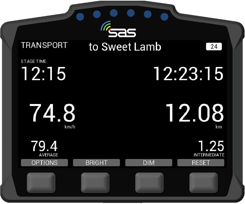
P a g e |7

   6. Antenna Installation
   All leads on both external and internal antennas must run on the inside of all roll cage bars. This is to
   stop cable crushing on impact.

   Antenna must not be mounted within 200 mm of any high frequency antenna’s or cabling

   The preferred route is to go down from the antenna, underneath the closest part of the roll cage (roof
   cross or main hoop), follow that along to the roof hoop, then go down the inside A pillar to the unit.
   Please allow 200mm clearance of high frequency antenna or cabling

   Any excess cable must be run so that the cable is not bent any tighter than a 100mm radius. We
   recommend running it across the underside of the dash and back (do not coil in tight loops).

   Cables must be tied neatly along the whole installation all the way to the unit so they can’t be accidently
   caught or dislodged.

   All this will be checked at scrutineering and you may be required to fix it before your car can pass.

   Note: All antenna connections need to be firmly tightened with an 8mm spanner.

   6.1. External Antenna
   The antenna is mounted through a 12mm hole in a central location on the ROOF of the vehicle, rear of
   the main roll bar hoop, allowing the cabling to pass through the roof and follow the cage bars back to
   the unit location. The antenna is a fully watertight unit, which seals against the roof surface.

   SAS Fitting Kit Manual – RALLY CAR                                                          Version 1.1

#ArcticRallyFinland                                      77
P a g e |8

 Antenna leads are connected as follows (There may be variations with the type and number of leads).

    1. The 2 UHF leads, colour-coded Blue, is connected to the terminal labelled "WiFi" on the WRC
       unit (Right Hand Thread). Terminals are located of the rear of the unit and/or colour-coded Blue.

    2. The Satellite Communication antenna lead is connected to the center or rear terminal labelled
       "IRI" (Left Hand Thread). It may also be colour-coded Yellow (this may be not marked on the 2-
       in-1 antenna).

    3. The GPS antenna lead labelled "GPS", is connected to the terminal labelled "GPS" on the WRC
       unit (Right Hand Thread). Terminals may be on the side or rear of the unit and/or colour-coded
       Green.

    4. GSM, has a small stick antenna supplied with the WRC unit, and is connected to corresponding
       terminal labelled "GSM" on the WRC unit (Left Hand Thread). The terminal is located on the rear
       of the unit and/or colour-coded Red.

 SAS Fitting Kit Manual – RALLY CAR                                                       Version 1.1

#ArcticRallyFinland                                       78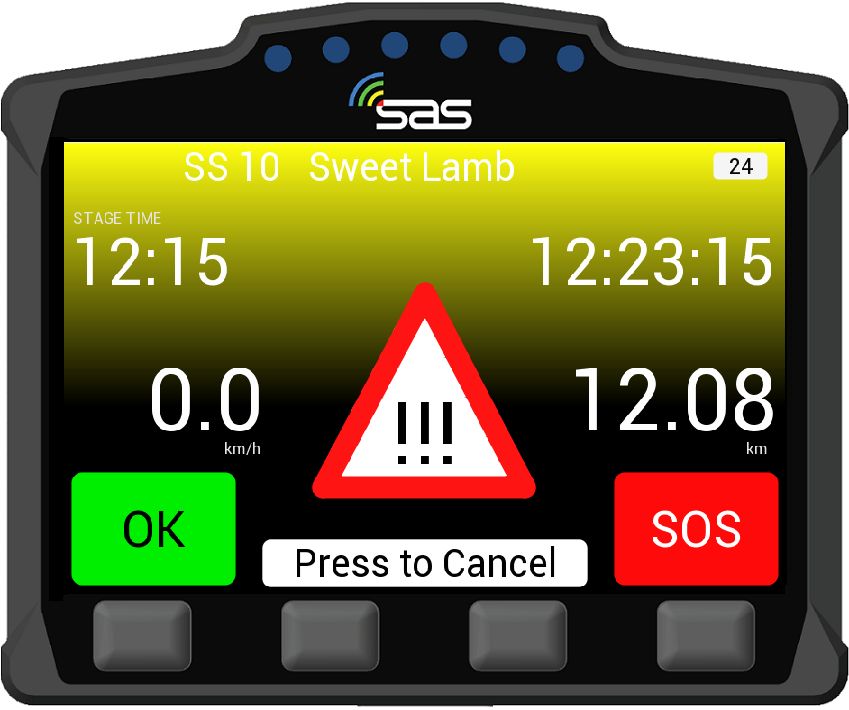
P a g e |9

   6.2. Internal Antenna
   The Internal Antenna should be placed on the inside of the ROOF in a clear uncluttered area, with a
   200mm radius clear of any bar work or solid metal object. The internal antenna has a magnetic base
   with double-sided tape for adhesion. The cable is then run to the WRC unit. Please keep cable on the
   inner side of the roll cage pipework so as not to be crushed in the event of an accident.

                        Figure 3. The internal antenna must be at least 200mm away from any roll cage components

   7. Contact Us
   For assistance, please contact the RallySafe Support Team by emailing: support@rallysafe.com.au

   **Product Disclaimer**

   “This manual, the specifications, and the material contained in it, as released by Status Awareness Systems and RallySafe, is
   for the purpose of information only. Due to continuous ongoing development, information and specifications may change at
   any time without notice. SAS, and the companies that have contributed to it, shall not be liable for any use of the manual or
   information supplied.
   The material contained in this manual is protected by copyright and other types of Intellectual Property Rights. The commercial
   exploitation of the material contained in this specification requires a license to such Intellectual Property Rights.
   This manual may be utilised or reproduced without any modification, in any form or by any means, for informational purposes
   only. For any other purpose, no part of the specification may be utilised or reproduced, in any form or by any means, without
   permission in writing from SAS.
   The word RallySafe and the RallySafe logo are registered trademarks”.

   SAS Fitting Kit Manual – RALLY CAR                                                                              Version 1.1

#ArcticRallyFinland                                                  79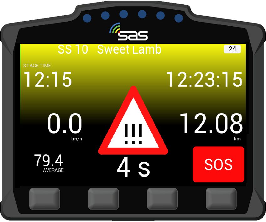
Appendix 5.2 - SAS Tracker User Manual
                                              Page |1

       SAS Tracker Competitor User Manual

SAS Tracker Competitor User Manual        Version 1.1

#ArcticRallyFinland                  80
Pa ge |2 Welcome For your and other competitor’s safety, it is important that you are familiar with the use of the WRC tracking unit, herein referred to as “the unit” or “the WRC tracking unit”. The SAS System is designed to increase competition safety by providing safety notifications to inform event management, improve response times and provide accurate and reliable event times. The following document outlines the basic features and functions of the WRC tracking unit. Please note that the WRC Tracking unit must be fitted and connected in all competitor’s car, in accordance with the SAS Fitting Kit Manual – RALLY CAR. Table of Contents 1. Powering The Unit On .................................................................................... 3 2. Stage Modes ........................................................................................ 3 2.1. Transport Mode ................................................................................... 3 2.2. Stage Mode ......................................................................................... 4 3. Hazard Alerts ........................................................................................ 6 4. Red Flag .............................................................................................. 8 5. Transport Menu .................................................................................... 9 5.1. Stage Times ...................................................................................... 10 5.2. Manual Hazard .................................................................................. 11 6. Contact Us ........................................................................................... 11 SAS Tracker Competitor User Manual Version 1.1 #ArcticRallyFinland 81
P a g e |3
1. Powering The Unit On
The unit is pre-loaded with all of the stage coordinates and is activated when powered on. Please power
the unit on early before the event to give it time to run checks.
When powered on the unit will display the transport mode, the details of which are specified in the Art.
2.1 of this document.
The unit does not need to be powered off at any stage during the event as it will go to sleep within a few
minutes of inactivity but can be re-woken by either moving the vehicle or pressing any of the four buttons.
It is recommended that the unit is not powered off during the event, to ensure the internal battery stays
fully charged for emergencies.
2. Unit Modes
The unit has two modes:
When not in a competitive stage, the unit will be in transport mode, as described in 2.1.
When in a competitive stage, the unit will go into stage mode, as described in 2.2.
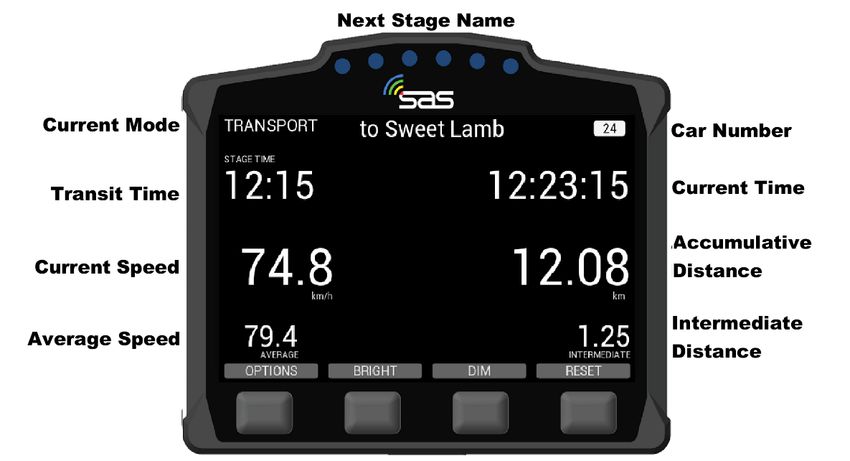
2.1. Transport Mode
SCREEN 1 – The transport mode displays from the top down the following information: the name of the
next point you are travelling to, the time in transit, current time, accumulative and intermediate distances
and speed, average speed.
The unit has four physical buttons. Their functions are reported on the screen right above the button’s
location.
Starting from the far left button to the right, you have the following options:
OPTIONS: Operation described in 5.Transport Menu.
BRIGHT: Increase the screen brightness (Note that the screen must always be clearly readable
so full brightness is recommended for daytime).
DIM: Decrease the screen brightness,
RESET: Intermediate trip meter.
SAS Tracker Competitor User Manual Version 1.1
#ArcticRallyFinland 82P a g e |4
SCREEN 1. Transport Mode
2.2. Stage Mode
SCREEN 2 – When the start official assigns each individual competitor a due start time, a countdown
will display on the unit as shown in the white field below. Also shown in the white field is the stage
number and the due start time.
SCREEN 2. Countdown to Stage Start
SAS Tracker Competitor User Manual Version 1.1
#ArcticRallyFinland 83P a g e |5
SCREEN 3 – Once the start time is reached, the screen will turn green as shown below and the
competitor has to proceed into stage.
SCREEN 3. Stage Start
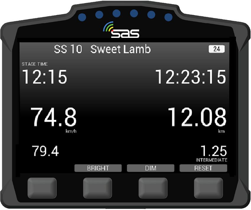
SCREEN 4 – Once the competitor has started the stage, the unit will automatically switch to on stage
mode. The unit will start timing.
SCREEN 4. Stage mode
SCREEN 5 – If the start is postponed for whatever reason and the start time is cancelled, the unit will
display the Transport Screen. Once it is clear to send cars again the official will re-issue a new start
time.
SAS Tracker Competitor User Manual Version 1.1
#ArcticRallyFinland 84Pa ge |6
SCREEN 5. Start Time Cancelled
3. Hazard Alerts
The unit’s primary function is to help alert race control of incidents on the course. The incident is notified
to race control with different levels of hazard depending on the severity.
SCREEN 6 – If a car stops during a stage for longer than 3 seconds, the unit will automatically transmit
a HAZARD notification; this can either upgraded to OK or downgraded to SOS by pressing the
corresponding button to the text. A timer counts up to 60 seconds as an indication to press the “OK”.
SCREEN 6. HAZARD Notification
SAS Tracker Competitor User Manual Version 1.1
#ArcticRallyFinland 85P a g e |7
SCREEN 7 – If you select OK after the HAZARD alert, then the following screen will appear, showing
that you and the car are OK.
SCREEN 7. OK Acknowledgment
SCREEN 8 – If the manual SOS button is pressed, it must be confirmed as either a fire or medical SOS
by pressing one of the two middle buttons It can also be cancelled if pressed by mistake. If a car is
involved in a High G impact, an automatic SOS message will display. If no urgent assistance is required,
you can downgrade to OK by selecting the corresponding button.
SCREEN 8. Confirm Fire SOS or Medical SOS
SAS Tracker Competitor User Manual Version 1.1
#ArcticRallyFinland 86P a g e |8
SCREEN 9 – When the SOS is confirmed, the screen 9 will display. Even once confirmed, the hazard
can be changed to OK. Pressing OK will inform race control that the crew are OK and do not need
medical assistance.
SCREEN 9. SOS Notification
4. Red Flag
SCREEN 10 – In the case of a serious incident, a stage may be red flagged from Race Control. The red
flag will display a full screen warning until it is acknowledged. To acknowledge the flag the far left button
must be pressed.
SAS Tracker Competitor User Manual Version 1.1
#ArcticRallyFinland 87Pa ge |9
SCREEN 10. RED FLAG Acknowledge
SCREEN 11 – Once the red flag has been acknowledged, normal stage functions will display with a
warning still at the top of the screen.
SCREEN 11. RED FLAG in Stage Mode
5. Transport Menu
SCREEN 12 – In transport mode, the unit has a menu that can be accessed by pressing the options
button.
SCREEN 12. Transport Mode
SAS Tracker Competitor User Manual Version 1.1
#ArcticRallyFinland 88P a g e | 10
SCREEN 13 – The option menu will allow the crew to view stage times “VIEW TIMES” or send a manual
hazard/SOS “SEND HAZARD”.
SCREEN 13. Transport Mode – View times/Send Hazard
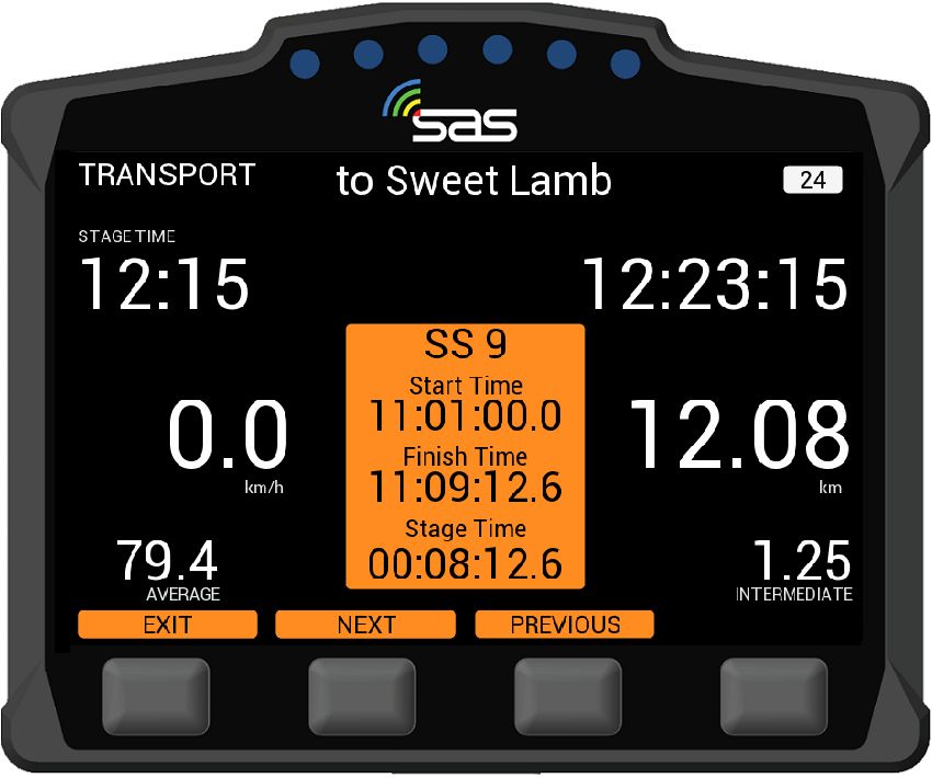
5.1. Stage Times
SCREEN 14 – By pressing the “VIEW TIMES” button, provisional transit and competitive stage times
will display. You can select times for any of the completed stages with the next and previous buttons.
SCREEN 14. Times of completed stages
SAS Tracker Competitor User Manual Version 1.1
#ArcticRallyFinland 89P a g e | 11
5.2. Manual Hazard
SCREEN 15 – If manual hazard is sent in transport mode, this can be upgraded or downgraded the
same way as a stage hazard. If the hazard is no longer required, it can also be cancelled by pressing
either of the two middle buttons “PRESS TO CANCEL”.
SCREEN 15. Manual Hazard in Transport Mode
6. Contact us
For assistance, please contact the RallySafe Support Team by emailing: info@statusas.com
Please be as descriptive as you can when describing the problem. It would help us is you provide the
following information at a minimum:
Name of event.
Vehicle or feature affected.
Stage of incident.
Time of incident.
Any additional details.
SAS Tracker Competitor User Manual Version 1.1
#ArcticRallyFinland 90You can also read


