DUAL EC THE ENERGY SAVER - INDIVIDUAL INNOVATIVE ENERGY-SAVING
←
→
Page content transcription
If your browser does not render page correctly, please read the page content below

DUAL  EC
                DUAL EC

   DUAL EC

DUAL EC
THE ENERGY SAVER

INDIVIDUAL
INNOVATIVE
ENERGY-SAVING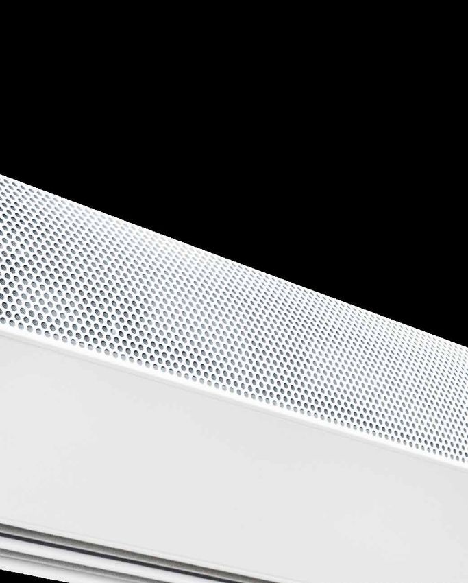
DUAL EC
THE ENERGY SAVER
+ Attractive intake grille
+ Self-supporting with micro-intake grille behind it
sheet steel housing
high-quality powder coated
+ Double discharge fins
each adjustable in 5 stages
+ Inspection panel
with hidden screws
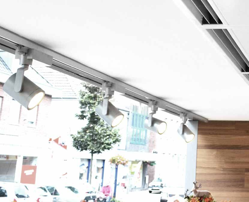
Applications The housing
Dual EC is the energy-saving model for applications in shops and Self-supporting sheet steel housing. Screws are not visible.
retail. Wherever there is only a limited supply of heating ener- High-quality powder coating, RAL 9016 as standard (traffic
gy available which must be used efficiently, the Dual EC has a white). Other colours are available.
special way of fulfilling all the requirements on a modern door air Inspection panel hidden behind the intake grille. Double,
curtain unit. Installation-ready model available in 3 installation var- aerodynamically-optimised aluminium discharge fins (naturally
iants. Free-hanging, installed flush with the ceiling as a cassette anodised), flush with the underside of the unit and adjustable in
unit or equipped with intake chamber and sliding supports for 5 stages. Perforated metal intake grille (same colour as the unit)
installation in a suspended ceiling. with micro grille behind it as an intake filter.
Special design Heating media
Equipped with 2 rows of fans, inside, 2 airflows are created – an A choice of heat exchangers for different heating media:
outer (unheated) and an inner (heated) airflow. The airflows are LPHW – for low temperature LPHW 60/40, other temperatures
routed separately all the way through to the discharge. Here, the available on request.
unheated outer airflow has a stabilising effect on the overall flow DX – soldered under nitrogen – for operation with heat pumps
behaviour, whereby a higher throw distance is achieved and the (only heating modus possible). High-quality heat exchanger made
shielding performance optimised. The saving in heating energy is from copper tubes, with pressed-on, extra-strong aluminium fins
around 40% compared with conventional door air curtains. for optimum heat transfer.
EC fans
The efficiency of the EC fans used by TEKADOOR is > 90%
2 under partial load operation. This is 30–35% higher than for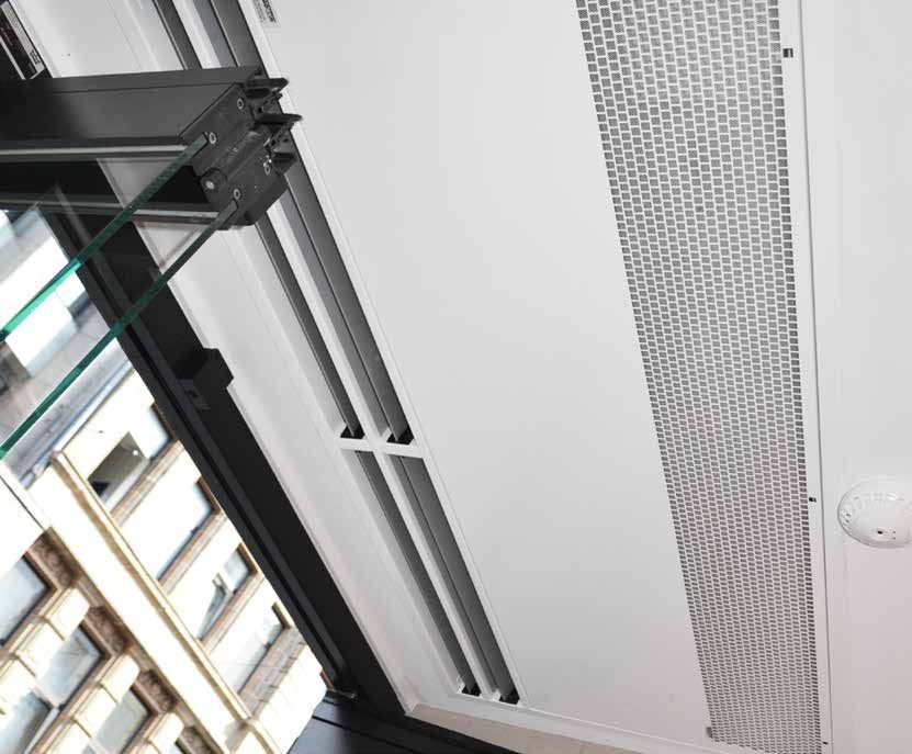
Advantages at a glance
                                             + Made in Germany
                                             + ErP conform / EC fans
                                             + Reduced heating costs
                                                   thanks to dual technology
                                             + Certified by TÜV-Süd
                                             + Robust, self-supporting
                                                   sheet steel housing
                                             + High-quality powder coating
                                             + Individual colours available
                                             + 3 installation types
                                             + Individual unit lengths up to 2500 mm
                                             + Easy-maintenance filter cleaning
                                                   thanks to micro grille

                                             + Aerodynamically optimised
                                                   double discharge fins
                                             + Different heating media possible

conventional AC fans. This does not just increase the efficiency,   Control
but also reduces the operating costs. The individually-driven       Electronic TEKADOOR GTC EC control unit, multifunctional
EC fans with integrated motor protection can intake air in both     with touch display, including an optional ModBus interface
directions. They have vibration-free bearings and are controlled    A GTC 1 EC control unit is used as standard for models with
using a PWM signal (pulse width modulation) – and with 0-10         LPHW heating. The units come with 20 m preassembled
V for the DX. They do not just comply with Directive ErP, but       and shielded data cable. The GTC 1 EC 5-stage control unit
actually exceed this standard.                                      includes the ability to switch from manual to automatic and from
                                                                    summer mode to winter mode as standard. A solenoid valve of
Mounting                                                            up to 2.5 A can be connected as an option for the winter mode.
Extremely simple mounting thanks to the rivet nuts (M8) incor-      The control unit includes a manual to automatic mode switch
porated on the upper side of the unit and optionally-available      and a potential-free contact for enabling via any
assembly materials. In the standard version, the unit does          on-site BMS or BEMS. A choice of 5-stage or stepless fan
not need to be opened for electrical connection. Connection         operation is offered as standard.
terminals for the voltage supply, as well as the connectors for     A maximum of 10 units can be connected in parallel.
the control unit and parallel operation can be accessed from the
outside.

Maintenance
Easy to clean (micro grille) without opening the unit by simply
vacuuming the intake grille. Discreet secured inspection panel
hidden on the lower side of the unit (hinges on one side) – easy
to open.                                                                                                                         3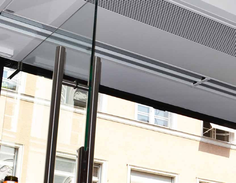
DUAL EC
DETAILS

Connections                                                     Connection box (LPHW)

Heating connections – flow and return – on top of the unit as   Simple electrical connection via connection box (voltage supply
standard for easy connection to the on-site heating system.     230V/50Hz on the top of the unit); connection can optionally
(Internal thread dimensions depend on the model).               also be located at the side.
Optionally, the connections can also be located at the side.
                                                                Exception:
                                                                Electrical units with a heating capacity greater than 22,5 kW.

4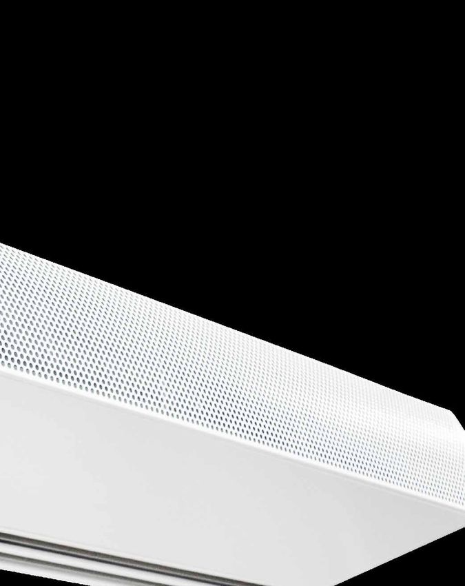
Data cable connection/interface                                   Double discharge fin

Simple, standard plug and play connection of the data cable       The shielding performance of the door air curtain unit is opti-
and an optional solenoid valve on the top side of the unit. The   mised by adjusting the discharge fins. The fins can be adjusted
connection can be offset on request.                              in 5 stages. During the heating period, the discharge fins should
                                                                  be tilted outwards by 10 to 15 degrees to prevent cold air
Control:                                                          coming in from the outside. In contrast, during operation in the
Input for the data cable to the control unit.                     summer, the fins are tilted inwards, so that the cooled indoor air
                                                                  cannot escape.
Auxiliary:
Output for parallel operation with other units.

                                                                                                                                 5
DUAL EC
INSTALLATION VARIANTS

6
Free-hanging

         TOP VIEW

                                          A
                                                                                  40

                                                                                        55
145115                                                                        505
                                               Connection box
           IN
                OUT       Circuit board                                                         SIDE VIEW

                                                                                                            220             Optional:
 75                                                                                          170                            Side connections
115
                                                                                               110

         FRONT VIEW

                                                                                  260            85
 30      BOTTOM VIEW

                                                                                                         Inspection panel
                                                                             30

630

                                  25                                              70
                                                                             60

      A = VARIABLE UNIT LENGTH                                       * WE RESERVE THE RIGHT TO MAKE TECHNICAL CHANGES

 Connection-ready free-hanging door air curtain unit for visible installation directly above the door.
 Ambient air intake is at the front, on the room side.

                                                                                                                                         7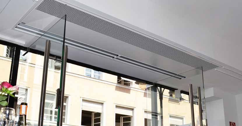
Cassette
          BOTTOM VIEW                                                                         hidden inspection
                                                                                                  panel screws

                                                                                                                     SIDE VIEW
                                                                                                                     Electrical and water connections at the
                                                                                                                     side

                                        25                                                    70
                                                                                         60
                                               A-50
                                                A

          FRONT VIEW

                   Pre-perforated for intake from the suspended ceiling
                                                                                                                      Inspection panel
                                                                                                   260               Intake filter with micro-filter
          TOP VIEW
                                                                                                                                                       340
                                                                                                                                                        290

                                                                                                                                          IN
                                                                                          730 780

                                                                                                                                                   OUT
                                                                                                                                                                    85
                                                                                                                                                               65
                       Fixation only for units longer than 2 m              9mm slot
                                                  M8 rivet nuts           for fixation
     35
25          M8

                                     movable

           50
                  40
            80

           A = VARIABLE UNIT LENGTH                                                                  * WE RESERVE THE RIGHT TO MAKE TECHNICAL CHANGES

     Connection-ready door air curtain unit with intake on the underside and surrounding frame for installation flush with the ceiling.
     Ambient air intake is from the underside, on the room side. Freely accessible inspection panel on the underside of the unit.

     8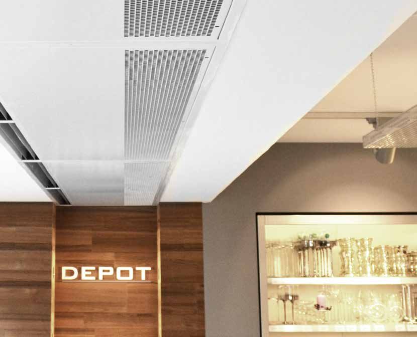
Suspended ceiling unit
            BOTTOM VIEW
  260

                                                                                               890
                                                                                    440
  190

                                                                                                         SIDE VIEW
                                                                                                                             890

            FRONT VIEW

                                                                                                                                                  260
                                                                                               130-230
                                        A

                                                                                        260

      15
                                                                                                                     Inspection panel
                                                                                                          60               440
                                                                                   45                                                   260
                                                                                                               70
            TOP VIEW

                                                                                          55

150
      115                                                          M8 Rivet nuts
                                                                                                           FRONT VIEW
             IN              Platine
                  OUT        Circuit board
                                             ONLY OUT
                                             WARNING

                             Print
                                                        CONTROL

                                                        AUXILIAR

                                                                                         70

 75
115

            A = VARIABLE UNIT LENGTH                                                      * WE RESERVE THE RIGHT TO MAKE TECHNICAL CHANGES

  Connection-ready door air curtain unit with intake chamber on the underside and intake and discharge sliding supports for installa-
  tion in a suspended ceiling. Only the intake and discharge grilles are visible from below. Ambient air intake is from the underside, on
  the room side.
  CAUTION: The inspection panel is on the underside of the unit. Therefore, it is essential that the suspended ceiling in which the unit
  is installed can be completely disassembled in the region between the intake grille and the discharge element.

                                                                                                                                              9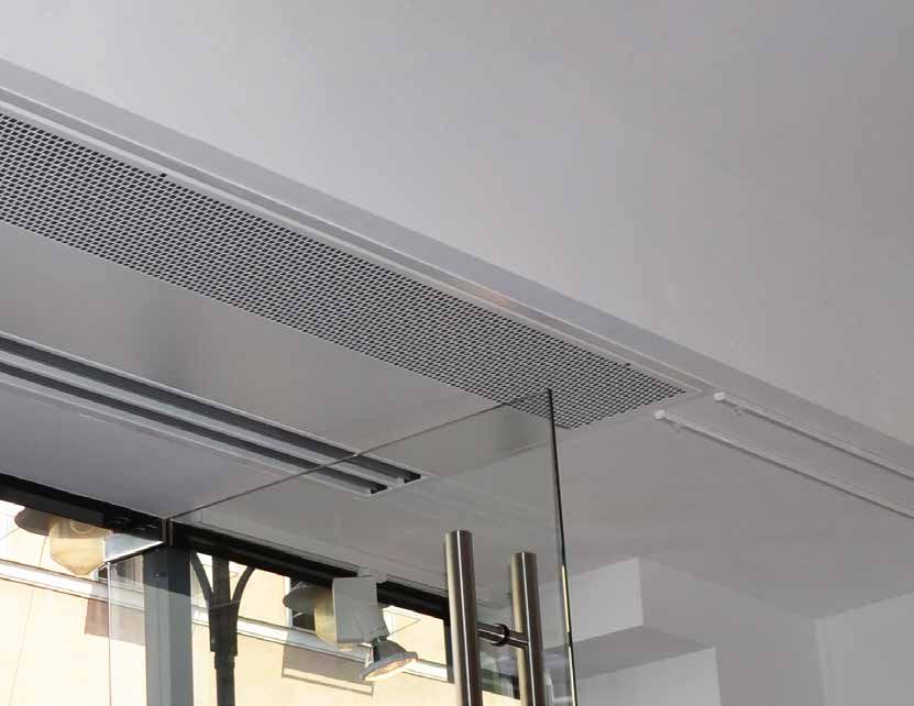
DUAL EC
    OPTIONAL ACCESSORIES

Thermostatic                         Solenoid valve                          Thermo-electric                    Ceiling attachment
straight-way valve                                                           shut-off valve                     set

(Setting range + 20 °C to + 35 °C)   Opens or closes the warm water          230 V / 50 Hz, normally closed.
limits the discharge temperature     circuit in the summer/winter            On-site installation in the        For problem-free, vibration free
(constant supply air temperature     setting of the control unit, in order   heating flow. Actuated by          ceiling attachment, consisting
limitation). Also available as a     to close the heating water circuit      the summer/ winter circuit.        of M8 or M10 threaded rods,
3-way valve.                         and save energy during summer           Summer function – closed. Winter   up to 1000 mm length, vibration
                                     operation or when the air curtain       function – opened.                 dampers, turnbuckles and coun-
                                     is not working (normally closed).                                          ter nuts.
                                     Caution: If solenoid valves are
                                     used, it is expressly recommend-
                                     ed to install a frost protection
                                     thermostat (automatically actuat-
                                     ed) and a strainer.

    10
Frost protection Control unit Electronic Door contact
thermostat GTC 2 EC control valve solenoid switch
For monitoring LPHW heat Possibility of combination of Electronic valve with 0-10V im- In automatic mode switches on
exchangers exposed to the risk various automatic operations. pulse and blow-out temperature the door air curtain in the
of frost. As soon as the temper- A constant discharge tempera- sensor completely installed and preselected stage
ature falls below +7 °C, the fans ture can be set via an optional wired. In combi-
are switched off and an optional electronic control valve, and a nation with the GTC 2 control, a
solenoid valve is opened. week timer is incorporated as preselected blow-out tempera-
standard, enabling up to 12 ture is kept constant.
different switching times to be
programmed per week.
11DUAL EC M
TECHNICAL DATA
FREE HANGING / CASSETTE
SUSPENDED CEILING
Design based on: recommended operating point
Intake temperature tLE = +20 °C
Discharge temperature tLA = +34 °C
Discharge height = up to 2.70 m
Model M1 M 1.5 M2 M 2.5
Total air quantity m3/h 1800 2700 3600 4500
Recirculating air quantity m3/h 600 900 1200 1500
Warm air quantity m /h
3
1200 1800 2400 3000
Heating capacity rated1 LPHW 60 / 40 °C kW 5.7 8.5 11.3 14.2
Flow rate LPHW 60 / 40 °C m /h
3
0.25 0.37 0.49 0.62
Water resistance LPHW 60 / 40 °C kPa 1.1 2.8 1.7 3.0
Nominal connection sizes Internal thread Inches 2 x 3/4" 2 x 3/4" 2 x 3/4" 2 x 3/4"
Flow/return DN 20 20 20 20
EC fans Voltage V 230 / 1 / N / PE
Frequency Hz 50
Max. current consumption A 1.6 2.4 3.2 4.0
Max. motor power kW 0.17 0.30 0.34 0.43
Sound pressure level 2 Highest setting dB (A) 58 59 60 61
Drawing dimension Unit length ( A ) mm 1000 1500 2000 2500
Unit height 3 mm 260 260 260 260
Unit depth 4
mm 660 660 660 660
Weight Dual kg 68 95 123 150
Cassette kg 75 106 136 168
Dual-Z kg 87 125 159 199
* WE RESERVE THE RIGHT TO MAKE TECHNICAL CHANGES
1. Rated operation based on operating point (see above), discharge temperature control recommended.
2. Measured at a lateral distance of 3 m. Sound pressure level may very depending on surrounding conditions.
3. For the Dual Z (suspended ceiling version), this dimension changes to 390-490 mm.
4. For the Dual Z this dimension changes to 890 mm and to 780 mm for the cassette (ceiling-flush version).
A well-balanced pressure ratio is one of the prerequisites for perfect function.
12DUAL EC L
TECHNICAL DATA
FREE HANGING / CASSETTE
SUSPENDED CEILING
Design based on: recommended operating point
Intake temperature tLE = +20 °C
Discharge temperature tLA = +34 °C
Discharge height = up to 3.00 m
Model L1 L 1.5 L2 L 2.5
Total air quantity m3/h 2700 3600 5100 6300
Recirculating air quantity m3/h 900 1200 1500 2100
Warm air quantity m /h
3
1800 2400 3600 4200
Heating capacity rated1 LPHW 60 / 40 °C kW 7.7 11.3 17.0 19.8
Flow rate LPHW 60 / 40 °C m3/h 0.34 0.49 0.74 0.86
Water resistance LPHW 60 / 40 °C kPa 2.1 4.9 5.8 5.6
Nominal connection sizes Internal thread Inches 2 x 3/4" 2 x 3/4" 2 x 3/4" 2 x 3/4"
Flow/return DN 20 20 20 20
EC fans Voltage V 230 / 1 / N / PE
Frequency Hz 50
Max. current consumption A 3.3 4.9 6.5 8.2
Max. motor power kW 0.39 0.59 0.78 0.98
Sound pressure level 2 Highest setting dB (A) 60 61 62 63
Drawing dimension Unit length ( A ) mm 1000 1500 2000 2500
Unit height 3
mm 260 260 260 260
Unit depth 4
mm 660 660 660 660
Weight Dual kg 75 103 130 158
Cassette kg 82 114 143 176
Dual-Z kg 94 133 166 207
* WE RESERVE THE RIGHT TO MAKE TECHNICAL CHANGES
1. Rated operation based on operating point (see above), discharge temperature control recommended.
2. Measured at a lateral distance of 3 m. Sound pressure level may very depending on surrounding conditions.
3. For the Dual Z (suspended ceiling version), this dimension changes to 390-490 mm.
4. For the Dual Z this dimension changes to 890 mm and to 780 mm for the cassette (ceiling-flush version).
A well-balanced pressure ratio is one of the prerequisites for perfect function.
13Design based on:
DUAL-DX M/L EC
TECHNICAL DATA
recommended operating point
intake temperature tLE = +20 °C
FREE HANGING / CASSETTE / SUSPENDED CEILING discharge temperature tLA = +34 °C
ONLY HEATING MODE POSSIBLE discharge height DX-M = up to 2.70 m
discharge height DX-L = up to 3.00 m
heating gas temperature = 70 °C
condensation temperature = 50 °C
condensate exit temp. = 45 °C
operating pressure = max. 45 bar
Model DX-M 1 DX-M 1.5 DX-M 2 DX-M 2.5
Total air quantity m /h
3
1800 2700 3600 4500
Recirculating air quantity m /h
3
600 900 1200 1500
Warm air quantity m3/h 1200 1800 2400 3000
Power 1
DX heating capacity kW 5.6 8.5 11.3 14.1
Delivery and intake line Connections mm 10/16 10/16 10/18 10/22
EC fans 3
Voltage V 230 / 1 / N / PE
Frequency Hz 50
Max. current consumption A 1.6 2.4 3.2 4.0
Max. motor power kW 0.17 0.30 0.34 0.43
Sound pressure level 2 Highest setting dB (A) 58 59 60 61
Drawing dimension Unit length ( A ) mm 1210 1710 2210 2710
Unit height mm 260 260 260 260
Unit depth mm 660 660 660 660
Weight Dual DX kg 74 102 131 159
Cassette kg 76 108 139 172
Dual-Z kg 88 127 162 203
Model DX-L 1 DX-L 1.5 DX-L 2 DX-L 2.5
Total air quantity m /h
3
2700 3600 5100 6300
Recirculating air quantity m /h
3
900 1200 1500 2100
Warm air quantity m3/h 1800 2400 3600 4200
Power 1
DX heating capacity kW 8.5 11.5 17.3 20.0
Delivery and intake line Connections mm 10/16 10/18 10/22 10/22
EC fans 3 Voltage V 230 / 1 / N / PE
Frequency Hz 50
Max. current consumption A 3.3 4.9 6.5 8.2
Max. motor power kW 0.39 0.59 0.78 0.98
Sound pressure level 2 Highest setting dB (A) 60 61 62 63
Drawing dimension Unit length ( A ) mm 1210 1710 2210 2710
Unit height mm 260 260 260 260
Unit depth mm 660 660 660 660
Weight Dual DX kg 81 110 138 167
Cassette kg 83 116 146 180
Dual-Z kg 95 135 169 211
* WE RESERVE THE RIGHT TO MAKE TECHNICAL CHANGES
1. Rated operation based on operating point (see above).
2. Measured at a lateral distance of 3 m. Sound pressure level may very depending on surrounding conditions.
3. Control voltage 0-10 V.
A well-balanced pressure ratio is one of the prerequisites for perfect function.
14DUAL EC
STANDARD CIRCUIT DIAGRAM FOR LPHW
ModBus
Fr 21.09.2018 Room Temp
07:52 10°C
Room temperature. Sensor installed
Heat level Fan level
0/0
Automatic
0/0
Timer
interface
Hand off
(optional)
1 2 3
Magnetic valve
(OPTIONAL) 1
to input (CONTROL) next PCB M ON
Address 1-9
Standard suppled L N PE
8 8 shielded datacable
(20 m) with next MOD Bus 1 2 3 4
RJ-45 connectors Fan
4 RJ 45
AUXILIAR CONTROL L2 N PE
230V / 50Hz L1
Magnetventil
L2 N PE N (OPTIONAL)
zum Steuerteil (CONTROL)
PE
AUX MON intern
weiss/white Adresse 1-9
Standard
imp.
gelb/yellow Y 0-10 V
Anschlusskabel
blau/blue 0V
8 8 (20 m) mit
PCB EC rot/red +10 V
RJ-45 Stecker
CPU
AUXILIAR CONTROL
901
78
2 3
F 16 AT
45 6
Address
switch
0 = MASTER AUX MON
1 - 9 = SLAVE
1 11 2 12 3 13 4 14 5 15 6 16 7 17 8 9 10 18 19 20 L N PE
Connecting box
Frost protection thermostat
Plati
Roomtemp. sensor
BMS On/Off
ext. Contact
nicht belegt
Main switch and fuses
Operation
not used
not used
to be installed by third
CPU
fault
parties must comply
q to all applicable rules and
3
requirements! 901
78
2 3
optional
optional
optional
45 6
230V/ 50Hz
Adress
Schalter
* WE RESERVE THE RIGHT TO MAKE
0 = MASTER
TECHNICAL CHANGES
Technical changes reserved 1 - 9 = SLAVE
Name Datum
gezeichnet/signet la 02.01.2019 CONTROL UNIT GTC 1 EC
Werkstoff
1 11 2 air
Maßstab
Multilingual, menu-driven electronic control unit for TEKADOOR 12 curtains
3 13 with
4 14 LPHW5 heating
15 6 and16 7 17 8
Frostschutzthermostat
energy-savingPos. EC fans. A standard
von feature
Gruppe of the control unit with touch display is a choice between
Teile
5-stage or
Kundenzeichnung Nr.:stageless fan control, which can be selected individually by the operator. The relevant
ext. Signalgeber
Erstelldatum
DDC- Freigabe
operating modes and symbols are arranged clearly on the colour display. The date, time and room
Benennung
GTC
temperature I EC
are shown as 190102
standard. The room temperature is monitored via an internal temperature
nicht belegt
nicht belegt
nicht belegt
nicht belegt
Name
Kunde Blatt
sensor in the control unit as standard. 1 von 1
An easy-to-navigate menu offers a selection of different operating modes:
Hand – manual operation
Auto AS – automatic operation via cool down protection
Auto RT – automatic operation via room temperature
Auto TK – automatic operation via door contact
Auto Kombi – option to combine all individual automatic modes
optional
optional
optional
An enabling contact and potential-free operation and malfunction signals are provided for control via
an on-site BMS or BEMS. Errors and faults are displayed with a red „warning“ sign. By coding the
control boards differently, up to 10 door air curtains can also be operated in parallel with 1 control unit,
using the Master/Slave principle. The control board is preinstalled in the door air curtain unit and 20 m
of preassembled data cable (connection between the door air curtain and controlDatum
Name unit) are included as
gezeichnet/signet la 07.03.2017
standard. Werkstoff
15www.TEKADOOR.de
German headquarters
TEKADOOR GmbH
Albert-Einstein-Str. 11
D-40764 Langenfeld
T. +49 (0) 2173 - 20766-0
F. +49 (0) 2173 - 20766-111
E. info@tekadoor.de
A = 01.07.2019You can also read