Specification for Approval - AM-320480-035NP - Customer: Model Name
←
→
Page content transcription
If your browser does not render page correctly, please read the page content below

Version: A
                    AM-320480-035NP
                                                       2019-03-18

     Specification for Approval

            Customer:
            Model Name:

            Supplier Approval                Customer approval
 R&D Designed   R&D Approved   QC Approved

    Peter        Peng Jun

YU DU AMSON ELECTRONICS CO.,LTD.                    Page 1 of 26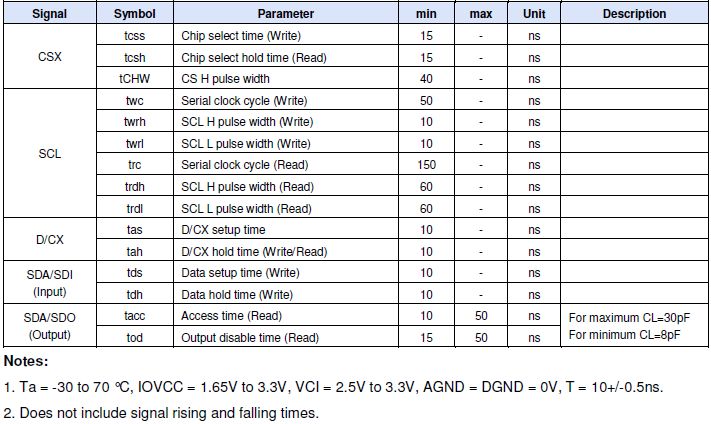
Version: A
                      AM-320480-035NP
                                              2019-03-18

                       Revision Record
    REV NO.   REV DATE         CONTENTS       Note
      A       2019-03-18       NEW ISSUE

YU DU AMSON ELECTRONICS CO.,LTD.           Page 2 of 26
Version: A
                        AM-320480-035NP
                                                      2019-03-18

                           Table of Contents

  List                             Description        Page No.
         Cover                                            1
         Revision Record                                  2
         Table of Contents                                3
   1     Scope                                            4
   2     General Information                              4
   3     External Dimensions                              5
   4     Interface Description                            6
   5     Absolute Maximum Ratings                         8
   6     DC Characteristics                               8
   7     Timing Characteristics                           9
   8     Backlight Characteristics                       16
   9     Optical Characteristics                         17
  10     Reliability Test Conditions And Methods         19
  11     Inspection Standard                             20
  12     Handling Precautions                            25
  13     Precaution for Use                              26
  14     Packing Method                                  26

YU DU AMSON ELECTRONICS CO.,LTD.                   Page 3 of 26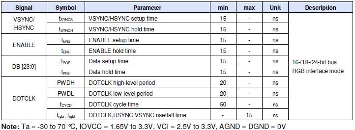
Version: A
                                AM-320480-035NP
                                                                               2019-03-18

1. Scope
  This specification defines general provisions as well as inspection standards for TFT module
  supplied by AMSON electronics.
  If the event of unforeseen problem or unspecified items may occur, naturally shall negotiate
  and agree to solution

2. General Information
TFT
                ITEM                            STANDARD VALUES                      UNITS
              LCD type                                 3.5’’TFT                        --
         Dot arrangement                           320(RGB)×480                       dots
           Color filter array                     RGB vertical stripe                  --
            Display mode                 IPS / Transmission / Normally Black            -
    Gray Scale Inversion Direction                   80/80/80/80                       --
       Eyes Viewing Direction                               ALL                        --
               Driver IC                               ST7796                          --
             Module size                     54.66(W)×82.94(H)×2.3(T)                 mm
             Active area                         48.96(W)×73.44(H)                    mm
               Dot pitch                           153(W)×153H)                       um
                                             MCU 8/9/16/18bit interface
               Interface                                                               --
                                       3wrie/4wrie SPI+16/18bit RGB interface
       Operating temperature                          -20 ~ +70                        °C
        Storage temperature                           -30 ~ +80                        °C
              Back Light                             6White LED                        --
                Weight                                   TBD                           g

CTP
              ITEM                           STANDARD VALUES                        UNITS

           CTP type                       Cover Lens + sensor + FPC                   --
        CTP Driver IC                              GT911                              --
        Surface Treatment                           6H                                --
        Transmittance                              ≥82%                               --
      The cover hardness                            6H                                --
           CTP size                        57.6(W)×98(H)×1.45(T)                     mm
       CTP Active area                        49.56(W)×70.04(H)                      mm
        CTP Interface                                 I2C
       response time                                   10                             ms
        Pointing Stick

YU DU AMSON ELECTRONICS CO.,LTD.                                          Page 4 of 26
Version: A
AM-320480-035NP
2019-03-18
3. External Dimensions
YU DU AMSON ELECTRONICS CO.,LTD. Page 5 of 26Version: A
AM-320480-035NP
2019-03-18
4. Interface Description
PIN NO. PIN NAME DESCRIPTION
1 LEDK The Anode of LED power
2 LEDA The cathode of LED power
3 NC NC
4 VCI Analog operating voltage.
5 IOVCC Logic operating voltage.
6~9 IM0~IM3 MPU interface mode select pin,(FYI NOTE1)
10 GND Power ground
11 VS Frame synchronizing signal for RGB interface operation.
12 HS Line synchronizing signal for RGB interface operation.
13 PCLK Dot clock signal for RGB interface operation.
14 DE Data enable signal for RGB interface operation.
15 GND Power ground
16-39 D0-D23 Data bus
Reset pin setting either pin low initializes the LSI
40 RESET
Must be reset after power supplied
41 RD Read signal input terminal, Active at ‘L’.
42 CS Chip select signal input terminal, Active at ‘L’
43 WR/SCL Serial clock input for SPI interfac
The SPI interface (DCX): The signal for command or
44 DCX
parameter select.
When IM [3]: Low, Serial in/out signal.
45 SDI When IM [3]: High, Serial input signal.
The data is applied on the rising edge of the SCL signal.
Serial output signal.
46 SDO
The data is applied on the rising edge of the SCL signal.
47 NC NC
48 NC NC
49 NC NC
50 NC NC
YU DU AMSON ELECTRONICS CO.,LTD. Page 6 of 26Version: A
AM-320480-035NP
2019-03-18
Note1: The System interface mode select
CTP
PIN NO. PIN NAME
1 GND CTP Power ground
2~5 NC NC
6 GND CTP Power ground
7 SDA CTP I2C_data
8 SCL CTP I2C_clock.
9 RESET CTP reset pin. Active low to enter reset state.
10 INT CTP interruption signal.
11,12 VDD CTP Digital Power.
YU DU AMSON ELECTRONICS CO.,LTD. Page 7 of 26Version: A
AM-320480-035NP
2019-03-18
5. Absolute Maximum Ratings
Item Symbol Min. Max. Unit
Logic Supply Voltage IOVCC -0.3 3.3 V
Analog Supply Voltage VCI -0.3 3.3 V
Input Voltage Vin -0.3 IOVCC+0.3 V
Operating Temperature TOP -30 70 °C
Storage Temperature TST -55 110 °C
Storage Humidity HD 20 90 %RH
6. DC Characteristics
Item Symbol Min. Typ. Max. Unit Remark
Logic Supply Voltage IOVCC 1.65 1.8 3.3 V -
Analog Supply Voltage VCI 2.5 2.8 3.3 V -
Input High Voltage VIH 0.7*IOVCC - IOVCC V -
Input Low Voltage VIL -0.3 - 0.3*IOVCC V -
Output High Voltage VOH 0.8*IOVCC - IOVCC V -
Output Low Voltage VOL GND - 0.2*IOVCC V -
I/O Leak Current ILI -1 - 1 uA -
YU DU AMSON ELECTRONICS CO.,LTD. Page 8 of 26Version: A
AM-320480-035NP
2019-03-18
7. Timing Characteristics
7.1 Reset Timing Characteristics
Reset Timing
Notes:
1. The reset cancel also includes the required time for loading ID bytes, VCOM setting and other
settings from the EEPROM to registers. After a rising edge of RESX, this loading is done
within 5 ms after the H/W reset cancel (tRT).
2. According to the Table 40, a spike due to an electrostatic discharge on the RESX line does not
cause irregular system reset.
Reset Description
3. During the Reset period, the display will be blanked (When Reset starts in the Sleep Out mode,
the display will enter the blanking sequence in at least 120 ms. The display remains the blank
state in the Sleep In mode.) and then return to the default condition for the Hardware Reset.
4. Spike Rejection can also be applied during a valid reset pulse, as shown below:
YU DU AMSON ELECTRONICS CO.,LTD. Page 9 of 26Version: A
AM-320480-035NP
2019-03-18
7.2 MCU 8/9/16/18-bit Timing Characteristics
1. Ta = -30 to 70 °C, IOVCC = 1.65V to 3.3V, VCI = 2.5V to 3.3V, AGND = DGND = 0V
2. Logic high and low levels are specified as 30% and 70% of IOVCC for input signals.
3. Input signal rising time and falling time:
4. The CSX timing:
YU DU AMSON ELECTRONICS CO.,LTD. Page 10 of 26Version: A
AM-320480-035NP
2019-03-18
5. The Write to Read or the Read to Write timing:
7.3 Display Serial Interface Timing Characteristics
3-wrie SPI system
YU DU AMSON ELECTRONICS CO.,LTD. Page 11 of 26Version: A
AM-320480-035NP
2019-03-18
4-wrie SPI system
YU DU AMSON ELECTRONICS CO.,LTD. Page 12 of 26Version: A
AM-320480-035NP
2019-03-18
7.4 Parallel 18/16-bit RGB Interface Timing Characteristics
YU DU AMSON ELECTRONICS CO.,LTD. Page 13 of 26Version: A
AM-320480-035NP
2019-03-18
7.5 CTP Timing characteristics
7.5.1 Serial Interface
I2C
YU DU AMSON ELECTRONICS CO.,LTD. Page 14 of 26Version: A
AM-320480-035NP
2019-03-18
7.5.2 POWER NO /Reset/Wake Sequence
YU DU AMSON ELECTRONICS CO.,LTD. Page 15 of 26Version: A
AM-320480-035NP
2019-03-18
8. Backlight Characteristics
BL CIRCUIT DIAGRAM
Item Symbol MIN TYP MAX UNIT Test Condition
Supply Voltage Vf 16.8 19.2 21 V If=20mA
Supply Current If - 20 - mA -
Luminous Intensity
- 250 300 - cd/m2 If=20mA
for LCM
Uniformity for LCM - 80 - - % If=20mA
Life Time - - 20000 - Hr If=20mA
Backlight Color White
YU DU AMSON ELECTRONICS CO.,LTD. Page 16 of 26Version: A
AM-320480-035NP
2019-03-18
9. Optical Characteristics
Item Conditions Min. Typ. Max. Unit Note
θL - 80 -
Horizontal
Viewing Angle θR - 80 -
degree (1),(2),(6)
(CR>10) θT - 80 -
Vertical
θB - 80 -
Contrast Ratio Center - 700 - - (1),(3),(6)
Response Time Rising + Falling - 30 - ms (1),(4),(6)
Red x TBD -
Red y TBD -
Green x TBD -
CF Color Green y TBD -
Typ. Typ.
Chromaticity (1), (6)
Blue x -0.05 TBD +0.05 -
(CIE1931)
Blue y TBD -
White x TBD -
White y TBD -
Note (1) Measurement Setup: The LCD module should be stabilized at given temp. 25°C for 15
minutes to avoid abrupt temperature change during measuring. In order to stabilize the
luminance, the measurement should be executed after lighting backlight for 15 minutes in a
windless room.
YU DU AMSON ELECTRONICS CO.,LTD. Page 17 of 26Version: A
AM-320480-035NP
2019-03-18
Note (2) Definition of Viewing Angle
Note (3) Definition Of Contrast Ratio (CR)
The contrast ratio can be calculated by the following expression
Contrast Ratio (CR) = L63 / L0
L63: Luminance of gray level 63, L0: Luminance of gray level 0
Note (4) Definition of response time
Note (5) Definition of Transmittance (Module is without signal input)
Transmittance = Center Luminance of LCD / Center Luminance of Back Light x 100%
Note (6) Definition of color chromaticity (CIE1931)
Color coordinates measured at the center point of LCD
YU DU AMSON ELECTRONICS CO.,LTD. Page 18 of 26Version: A
AM-320480-035NP
2019-03-18
10. Reliability Test Conditions and Methods
INSPECTION AFTER
NO. TEST ITEMS TEST CONDITION
TEST
High Temperature
80°C±2°C×96Hours
Storage
Low Temperature
-30°C±2°C×96Hours
Storage
High Temperature
70°C±2°C×96Hours
Operating
Inspection after 2~4hours
Low Temperature
-20°C±2°C×96Hours storage at room
Operating
temperature, the samples
should be free from
-20°C 25°C 70°C defects:
Temperature (30min) (5min) (30min) 1, Air bubble in the LCD.
Cycle(Storage) 1cycle 2, Seal leak.
Total 10cycle 3, Non-display.
4, Missing segments.
Damp Proof 5, Glass crack.
50°C±5°C×90%RH×96Hours
Test (Storage) 6, Current IDD is twice
Frequency:10Hz~55Hz~10Hz higher than initial value.
Amplitude:1.5MM 7, The surface shall be free
Vibration Test X,Y,Z direction for total 3hours from damage.
(packing condition test will be 8, The electric
tested by a carton) characteristic requirements
shall be satisfied.
Drop to the ground from 1M height
one time
Drooping Test every side of carton.
(packing condition test will be
tested by a carton)
Voltage:±8KV,R:330Ω,C:150PF,Air
ESD Test
Mode,10times
REMARK:
1, The Test samples should be applied to only one test item.
2, Sample side for each test item is 5~10pcs.
3,For Damp Proof Test, Pure water(Resistance>10MΩ)should be used.
4,In case of malfunction defect caused by ESD damage, if it would be recovered to normal
state after resetting, it would be judge as a good part.
5, EL evaluation should be accepted from reliability test with humidity and temperature: Some
defects such as black spot/blemish can happen by natural chemical reaction with humidity
and Fluorescence EL has.
6, Failure Judgment Criterion: Basic Specification Electrical Characteristic, Mechanical
Characteristic, Optical Characteristic.
YU DU AMSON ELECTRONICS CO.,LTD. Page 19 of 26Version: A
AM-320480-035NP
2019-03-18
11. Inspection Standard
YU DU AMSON ELECTRONICS CO.,LTD. Page 20 of 26Version: A
AM-320480-035NP
2019-03-18
YU DU AMSON ELECTRONICS CO.,LTD. Page 21 of 26Version: A
AM-320480-035NP
2019-03-18
YU DU AMSON ELECTRONICS CO.,LTD. Page 22 of 26Version: A
AM-320480-035NP
2019-03-18
YU DU AMSON ELECTRONICS CO.,LTD. Page 23 of 26Version: A
AM-320480-035NP
2019-03-18
YU DU AMSON ELECTRONICS CO.,LTD. Page 24 of 26Version: A
AM-320480-035NP
2019-03-18
12. Handling Precautions
12.1 Mounting method
The LCD panel of AMSON TFT module consists of two thin glass plates with polarizes
which easily be damaged. And since the module in so constructed as to be fixed by utilizing
fitting holes in the printed circuit board.
Extreme care should be needed when handling the LCD modules.
12.2 Caution of LCD handling and cleaning
When cleaning the display surface, Use soft cloth with solvent
[Recommended below] and wipe lightly
z Isopropyl alcohol
z Ethyl alcohol
Do not wipe the display surface with dry or hard materials that will damage the polarizer
surface.
Do not use the following solvent:
z Water
z Aromatics
Do not wipe ITO pad area with the dry or hard materials that will damage the ITO patterns
Do not use the following solvent on the pad or prevent it from being contaminated:
z Soldering flux
z Chlorine (Cl) , Sulfur (S)
If goods were sent without being silicon coated on the pad, ITO patterns could be damaged
due to the corrosion as time goes on.
If ITO corrosion happen by miss-handling or using some materials such as Chlorine (CI),
Sulfur (S) from customer, Responsibility is on customer.
12.3 Caution against static charge
The LCD module use C-MOS LSI drivers, so we recommended that you:
Connect any unused input terminal to VDD or GND, do not input any signals before power is
turned on, and ground your body, work/assembly areas, and assembly equipment to protect
against static electricity.
12.4 packing
z Module employs LCD elements and must be treated as such.
z Avoid intense shock and falls from a height.
z To prevent modules from degradation, do not operate or store them exposed direct to
sunshine or high temperature/humidity
12.5 Caution for operation
z It is an indispensable condition to drive LCD’s within the specified voltage limit since the
higher voltage then the limit cause the shorter LCD life.
z An electrochemical reaction due to direct current causes LCD’s undesirable deterioration,
so that the use of direct current drive should be avoided.
z Response time will be extremely delayed at lower temperature then the operating
temperature range and on the other hand at higher temperature LCD’s how dark color in
them. However those phenomena do not mean malfunction or out of order with LCD’s,
which will come back in the specified operation temperature.
z If the display area is pushed hard during operation, some font will be abnormally displayed
but it resumes normal condition after turning off once.
z Slight dew depositing on terminals is a cause for electro-chemical reaction resulting in
terminal open circuit.
Usage under the maximum operating temperature, 50%Rh or less is required.
YU DU AMSON ELECTRONICS CO.,LTD. Page 25 of 26Version: A
AM-320480-035NP
2019-03-18
12.6 storing
In the case of storing for a long period of time for instance, for years for the purpose or
replacement use, the following ways are recommended.
z Storage in a polyethylene bag with the opening sealed so as not to enter fresh air outside in
it. And with no desiccant.
z Placing in a dark place where neither exposure to direct sunlight nor light’s keeping the
storage temperature range.
z Storing with no touch on polarizer surface by the anything else.
[It is recommended to store them as they have been contained in the inner container at the
time of delivery from us
12.7 Safety
z It is recommendable to crash damaged or unnecessary LCD’s into pieces and wash off
liquid crystal by either of solvents such as acetone and ethanol, which should be burned up
later.
z When any liquid leaked out of a damaged glass cell comes in contact with your hands,
please wash it off well with soap and water
13. Precaution for Use
13.1
A limit sample should be provided by the both parties on an occasion when the both parties
agreed its necessity. Judgment by a limit sample shall take effect after the limit sample has been
established and confirmed by the both parties.
13.2
On the following occasions, the handing of problem should be decided through discussion
and agreement between responsible of the both parties.
z When a question is arisen in this specification
z When a new problem is arisen which is not specified in this specifications
z When an inspection specifications change or operating condition change in customer is
reported to AMSON TFT , and some problem is arisen in this specification due to the
change
z When a new problem is arisen at the customer’s operating set for sample evaluation in the
customer site.
14. Packing Method
TBD
YU DU AMSON ELECTRONICS CO.,LTD. Page 26 of 26You can also read