Backdraft & Pressure Relief Dampers - Backdraft Barometric Relief Pressure Relief - Greenheck
←
→
Page content transcription
If your browser does not render page correctly, please read the page content below

Backdraft & Pressure Relief Dampers
• Backdraft
• Barometric Relief
• Pressure Relief

                               September
                                   2021
Backdraft Dampers

    Backdraft dampers (also known as gravity dampers) are used in ventilation systems to allow airflow in one
    direction and prevent airflow in the opposite direction. A relief damper is developed with an elevated and
    adjustable start-open pressure while providing the backdraft function. The following information is needed
    when selecting the proper damper application.
    	• System velocity and back pressure requirements
      • Mounting orientation and airflow direction
      • Mounting configuration (inserted into duct/opening or flange mounted)
      • Damper operation (gravity or motorized)
      • Start-open pressure

    Mounting Orientation
    Backdraft dampers are available in vertical or horizontal mount.

                                                    Airflow

                                                  Horizontal Mount
                                                     Airflow Up

                                                   Airflow

                      Vertical Mount                Horizontal Mount
                                                     Airflow Down

    Frame Construction
    Three types of frame construction are available on all commercial backdraft damper models:
        • No flange
        • Flange on discharge
        • Flange on intake
                                       Duct

                                 Airflow
                                  Airflow                     Airflow                  Airflow

                                       Duct

                       No
                        NoFlange
                           Flange                  Flange On               Flange On
                        (Duct Insert)              Discharge                 Intake

2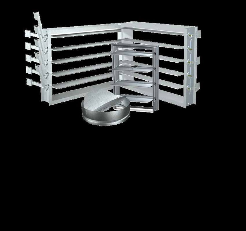
Commercial Backdraft
Dampers
A commercial backdraft damper is a gravity damper (when non-motorized) that allows airflow in one direction only.
When placed on a propeller fan, for example, it will prevent the wind from causing the fan to run backwards when
the power is off. A motorized backdraft damper functions like a control damper.
To assist with opening the damper blades, backdraft dampers may utilize springs, adjustable counterbalance
weights, or a motorpack.
    • Spring assist is a spring attached to the damper that helps in opening or closing the damper blades.
       The spring is adjustable by using a series of holes in the frame or blade assembly to increase or decrease
       the tension.
    • Adjustable counterbalance weights are a more precise means of reducing the pressure that is required to
       open the damper.
    • A motorpack is used when it is necessary that the damper opens and closes without having to rely on air
       velocity or pressure.
Backdraft damper selection begins by determining the damper construction required based on system velocity and
static pressure. The BD damper series is used in applications up to 1500 ft/min (7 m/s) and 2 in. wg (0.5 kPa) of
static pressure. The WD, ES, GM, and SSNM damper series are used in applications up to 2500 ft/min (12.7 m/s)
and 2 in. wg (0.5 kPa) of static pressure. The EM damper series is used in applications up to 3500 ft/min (17.8 m/s)
and 10 in. wg (2.5 kPa) of static pressure.
BD, EM, ES, GM, SSNM, and WD series dampers can be used in applications for:
    • Exhaust                       • Roof ventilation                     • In-duct ventilation
    • Air intake                    • Sidewall ventilation

BD Series
BD series have a galvanized steel frame with aluminum blades. The dampers are opened by air pressure differential
and closed by gravity. They are rated for velocities up to 1500 fpm (7 m/s) and pressures up to 2 in. wg (0.5 kPa).
These dampers have AMCA certified pressure drop and leakage performance that comply with ASHRAE 90.1 and
IECC leakage requirements for non-motorized dampers.

             BD-100
                                                                                                        BD-300 Series

                                                                           Maximum          Start Open        Maximum         AMCA Air
                             Mounting Airflow             Spring
  Model          Flange                                                     Velocity        Pressure*       Back Pressure   Leakage & Air
                             Position Direction          Assisted
                                                                           fpm (m/s)       in. wg (kPa)      in. wg (kPa)   Performance
                                              Vertical                         1500             0.01               2
  BD-100           None             H                         Std                                                                Yes
                                                Up                              (7)           (0.002)            (0.5)
                                                                               1500            0.009               2
  BD-300          Intake            V            H            N/A                                                                Yes
                                                                                (7)           (0.002)            (0.5)
                                                                               1500            0.009               2
  BD-320         Discharge          V            H            N/A                                                                Yes
                                                                                (7)           (0.002)            (0.5)
                                                                               1500            0.009               2
  BD-330           None             V            H            N/A                                                                Yes
                                                                                (7)           (0.002)            (0.5)
H = Horizontal       V = Vertical       N/A = Not Available         Std = Standard
*Start-open is the pressure at which the damper blades begin to rotate. The blades are not fully open at this point.
  Damper size and bearing selection may cause start-open pressure to vary from this value.

                                                                                                                                            3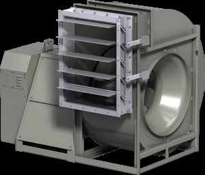
Commercial Backdraft
    WD Series
    The WD series backdraft dampers are constructed of a galvanized steel frame and aluminum blades with seals. The
    dampers are opened by air pressure differential (assisted by springs) and closed by gravity. When motorized, the
    damper functions like a control damper. WD series dampers are rated for velocities up to 2500 ft/min (12.7 m/s) and
    pressures up to 2 in. wg (0.5 kPa).

    WD-100 Series
    WD-100 series dampers are horizontally mounted to
    allow vertical airflow. The primary application is with roof
    mounted exhaust fans. Optional motorpack is available.

    WD-200 Series
                                                                   WD-100 Series
    WD-200 series dampers are electric motorized
    backdraft dampers that open when energized and
    spring return close when de-energized. These
    dampers can be used for horizontal or vertical mount
    applications. The primary application is to prevent
    undesirable reverse airflow when installed with roof
    or sidewall supply (intake) fans.

    WD-300 Series
    WD-300 series dampers are vertically mounted for
    horizontal exhaust applications. These dampers are
    designed to open easily under low velocity conditions.
    Optional motorpack is available.
                                                                                        WD-200 Series
    WD-400 Series
    WD-400 series dampers are non-motorized and can
    be mounted vertically (for horizontal intake airflow) or
    horizontally (for vertical airflow down).

    WDR-53/SSWDR-53
    WDR-53 and SSWDR-53 are round backdraft dampers.
    These models can be mounted horizontally for vertical
    airflow down or up, or mounted vertically for horizontal
    airflow. The WDR-53 and SSWDR-53 are rated for
    velocities up to 2000 ft/min (10.2 m/s) and pressure
                                                                   WDR-53/SSWDR-53
    up to 3 in. wg (0.75 kPa).

    End Switch Kits
    An end switch kit can be used in conjunction with a
    motorpack. The end switch is wired to a fan and/or to
    a light serving as an open/closed indicator. When wired
    to a fan, this will ensure the damper is fully open before
    the fan starts.

                                                                                                End Switch Kit

4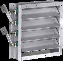
Commercial Backdraft
WD Series
Maximum
Maximum Start Open
Mounting Airflow Spring Back
Model Flange Motorized Velocity Pressure*
Position Direction Assisted Pressure
fpm (m/s) in. wg (kPa)
in. wg (kPa)
Vertical 2500 0.01 1
WD-100 None H Std Opt
Up (12.7) (0.002) (0.25)
Vertical 2500 0.01 1
WD-110 Discharge H Std Opt
Up (12.7) (0.002) (0.25)
Vertical 2500 0.01 1
WD-120 Intake H Std Opt
Up (12.7) (0.002) (0.25)
2500 0.017 1
WD-200 None H or V H or V N/A Std
(12.7) (0.004) (0.25)
2500 0.017 1
WD-210 Motor Side H or V H or V N/A Std
(12.7) (0.004) (0.25)
Opposite 2500 0.017 1
WD-220 H or V H or V N/A Std
Motor Side (12.7) (0.004) (0.25)
2500 0.05 2
WD-300 Intake V H N/A Opt
(12.7) (0.012) (0.5)
2500 0.05 2
WD-320 Discharge V H N/A Opt
(12.7) (0.012) (0.5)
2500 0.05 2
WD-330 None V H N/A Opt
(12.7) (0.012) (0.5)
2500 0.026 2
WD-400 None V H N/A N/A
(12.7) (0.006) (0.5)
Vertical 2500 0.014 2
WD-410 None H N/A N/A
Down (12.7) (0.003) (0.5)
2500 0.026 2
WD-420 Discharge V H N/A N/A
(12.7) (0.006) (0.5)
2500 0.026 2
WD-430 Intake V H N/A N/A
(12.7) (0.006) (0.5)
2000 0.08 3
WDR-53 None H or V H or V Std N/A
(10.2) (0.020) (0.75)
2000 0.08 3
SSWDR-53 None H or V H or V Std N/A
(10.2) (0.020) (0.75)
H = Horizontal V = Vertical N/A = Not Available Opt = Optional Std = Standard
*Start-open is the pressure at which the damper blades begin to rotate. The blades are not fully open at this point.
Damper size and bearing selection may cause start-open pressure to vary from this value.
5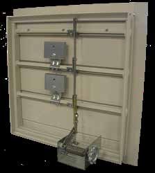
Commercial Backdraft
    EM, ES, GM & SSNM Series
    EM Series
    EM series dampers have 0.070 inch (1.8mm) thick blades
    and a 0.125 inch (3.2mm) thick frame made of extruded
    aluminum. These dampers are rated for velocities up to
    3500 fpm (17.8 m/s) and pressure up to 10 in. wg (2.5 kPa).
    EM-30 series comply with ASHRAE 90.1 and IECC leakage
    requirements for non-motorized dampers.
    Adjustable pressure controller is available for field setting
    of relief pressure. Paint is available on these models.

    ES Series
    ES series dampers have 0.050 inch (1.3mm) thick blades                EM-30 Series
    and a 0.063 inch (1.6mm) thick frame made of extruded
    aluminum. They are rated for velocities up to 2000 fpm
    (10.2 m/s) and pressure up to 6 in. wg (1.5 kPa). ES-10 and
    ES-30 series comply with ASHRAE 90.1 and IECC leakage
    requirements for non-motorized dampers.

    GM Series
    GM series dampers have a galvanized steel frame with                  ES-10 Series
    extruded aluminum blades. This series is rated for
    velocities up to 2500 fpm (13 m/s) and pressure up to
    4 in. wg (1 kPa).

    SSNM Series
    SSNM series dampers have 304SS blades and frame.
    These dampers are rated for velocities up to 2500 fpm
    (13 m/s) and pressure up to 2 in. wg (.5 kPa).                        ES-40 Series

                     EM-30 with adjustable pressure controller      SSNM-30 Series

6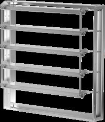
Commercial Backdraft
EM, ES, GM & SSNM Series
Maximum Maximum
Counter- Start-Open AMCA Air
Frame Blade Mounting Airflow Velocity Back
Model Flange balance Pressure* Leakage & Air
Material Material Position Direction ft/min. Pressure
Weights in. wg (kPa) Performance
(m/s) in. wg (kPa)
EM-10 None
Extruded Vertical 3500 10 0.05
EM-11 Discharge Std H N/A
Aluminum Up (17.8) (2.5) (0.01)
EM-12 Intake
EM-30 None
Extruded 3500 10 0.03 (0.007)1
EM-31 Discharge Opt V Horizontal Yes
Aluminum (17.8) (2.5) 0.01 (0.002)2
EM-32 Intake
EM-40 None
Extruded Vertical 3500 10 0.07
EM-41 Discharge Std H N/A
Aluminum Down (17.8) (2.5) (0.017)
EM-42 Intake
ES-10 None
Extruded Vertical 2000 6 0.035
ES-11 Discharge Std H Yes
Aluminum Up (10.2) (1.5)3 (0.008)
ES-12 Intake
ES-30 None
Extruded 2000 6 0.05 (0.012)1
ES-31 Discharge Opt V Horizontal Yes
Aluminum (10.2) (1.5)3 0.015 (0.004)2
ES-32 Intake
ES-40 None
Extruded Vertical 2000 2.5 0.075
ES-41 Discharge Std H N/A
Aluminum Down (10.2) (0.6) (0.019)
ES-42 Intake
GM-30 None
Galvanized Extruded 2500 4 0.03 (0.007)1
GM-31 Discharge Std V Horizontal N/A
Steel Aluminum (13) (1) 0.01 (0.002)2
GM-32 Intake
SSNM-10 None
Vertical 2500 2
SSNM-11 Discharge 304SS N/A H CF N/A
Up (13) (0.5)
SSNM-12 Intake
SSNM-30 None
2500 2
SSNM-31 Discharge 304SS N/A V Horizontal CF N/A
(13) (0.5)
SSNM-32 Intake
H = Horizontal V = Vertical N/A = Not Available CF = Consult Factory Opt = Optional Std = Standard
1
= without weights
2
= with weights
= depending on damper width
3
*Start-open is the pressure at which the damper blades just begin to rotate. The blades are not fully open at this point.
Damper size and bearing selection may cause start-open pressure to vary from this value.
7Heavy Duty/Industrial
Backdraft - HB & HBR Series
Heavy duty/industrial backdraft dampers are designed to
prevent backflow at static pressures up to 20 in. wg (5 kPa)
and velocities up to 6400 ft/min (32.5 m/s). Counterbalance
weights are mounted externally for easy adjustment and
balancing in the field.
The HB series dampers are flange frame mounted. Width
and height dimensions are to the inside of the frame.
HB and HBR series dampers can be used in
applications for:
• Blower outlets
• Branch duct isolation
• Industrial process isolation
• Emergency generator radiator outlets HBR-050
HBR-050 & HBR-150
• Round frame and blade
• Corrosion resistant
• Optional 304 or 316 stainless steel construction
HB-110
• Corrosion resistant
• Spark B and C resistant
• Optional 304 or 316 stainless steel construction HB-110
HB-120
• Optional 304 or 316 stainless steel construction
HB-230
• Optional 304 or 316 stainless steel construction
HB-240
• Spark B and C resistant
• Optional Spark A resistant
HB-120
• Optional 304 or 316 stainless steel construction
(except blades)
HB-330
• Fan Class III
• Optional 304 or 316 stainless steel construction
HB-330
Note: HB series dampers are flange frame mounted. Width and height dimensions are to the inside of the frame.
8Heavy Duty/Industrial
Backdraft - HB & HBR Series
Material Maximum Maximum Back Start-Open
Counterbalance
Model Velocity Pressure Pressure*
Weights
Frame Blade ft/min. (m/s) in. wg (kPa) in. wg (kPa)
HBR-050 Galvanized Steel Galvanized Steel Std 3000 (15.2) 6 (1.5) 0.12 (0.03)
HBR-150 Painted Steel Painted Steel Std 4000 (20.3) 6 (1.5) N/A
HB-110 Galvanized Steel Aluminum Single Std 3900 (20) 5 (1.2) 0.02 (0.005)
HB-120 Galvanized Steel Galvanized Steel 2V Std 5150 (26) 8.5 (2.1) 0.045 (0.11)
Galvanized Steel
HB-230 Galvanized Steel Std 5150 (26) 13.5 (3.4) 0.04 (0.010)
Airfoil
Extruded Aluminum
HB-240 Galvanized Steel Std 5150 (26) 13.5 (3.4) 0.04 (0.010)
Airfoil
Galvanized Steel
HB-330 Galvanized Steel Std 6400 (33) 20 (5) 0.25 (0.06)
Airfoil
N/A = Not Applicable Std = Standard
*Start-open is the pressure at which the damper blades just begin to rotate. The blades are not fully open at this point.
Damper size and bearing selection may cause start-open pressure to vary from this value.
Fan Accessory
Industrial Backdraft Dampers
Industrial backdraft dampers are used on blower
outlets for automatic isolation which allows air
to pass in one direction and restrict flow in the
opposite direction. Each damper is factory-adjusted
for its intended flow direction. Multiple nested
counterbalance arms and weights are positioned
to reduce load on bearings and linkage. Industrial
backdraft dampers are recommended for low
temperatures and clean air applications. HB-230
Relief Dampers
Relief dampers are backdraft dampers with an adjustable start-open pressure capable of maintaining a relatively
constant pressure at various airflows and which closes upon a decrease in differential pressure. Suitable to relieve
built-up pressure in a zoned duct system that could potentially cause damage to HVAC equipment.
BR-40 Series
HPR-120
9Barometric Relief
BR and SEBR Series
A barometric relief damper is a backdraft damper with an
adjustable start-open pressure. It is used for gravity ventilation
and low-velocity systems. Counterbalance weights provide the
ability to fine-tune start-to-open and full-open operations.
BR series dampers are constructed with a galvanized steel frame
and aluminum blades. The SEBR series is constructed of 316
stainless steel for severe or corrosive environments. Vinyl blade
seals are used on both series of dampers. These dampers are
rated for velocities up to 2000 ft/min (10.2 m/s) and back pressure
up to 2 in. wg (0.5 kPa). The start-open pressure is selectable
from .05 to .13 in. wg (0.01 kPa to .03 kPa).
BR and SEBR series dampers can be used in applications for:
• Gravity hood intake and exhaust BR-30 Series
• Stairwell pressurization
• Room pressurization
• Ductwork outlets
BR-10 Series
Material Maximum
Maximum Start-Open
Mounting Airflow Back
Model Flange Velocity Pressure*
Position Direction Pressure
Frame Blade ft/min. (m/s) in. wg (kPa)
in. wg (kPa)
BR-10 None H Vertical Up
2000 2 0.05 - 0.30
BR-11 Discharge H Vertical Up
(10.2) (0.5) (0.012-0.075)
BR-12 Intake H Vertical Up
BR-30 None V H
Galvanized 2000 2 0.05 - 0.30
BR-31 Discharge Aluminum V H
Steel (10.2) (0.5) (0.012-0.075)
BR-32 Intake V H
BR-40 None H Vertical Down
2000 2 0.05 - 0.30
BR-41 Discharge H Vertical Down
(10.2) (0.5) (0.012-0.075)
BR-42 Intake H Vertical Down
SEBR-10 None H Vertical Up
2000 2 0.05 - 0.30
SEBR-11 Discharge H Vertical Up
(10.2) (0.5) (0.012-0.075)
SEBR-12 Intake H Vertical Up
SEBR-30 None V H
316 Stainless 316 Stainless 2000 2 0.05 - 0.30
SEBR-31 Discharge V H
Steel Steel (10.2) (0.5) (0.012-0.075)
SEBR-32 Intake V H
SEBR-40 None H Vertical Down
2000 2 0.05 - 0.30
SEBR-41 Discharge H Vertical Down
(10.2) (0.5) (0.012-0.075)
SEBR-42 Intake H Vertical Down
H = Horizontal V = Vertical
*Start-open is the pressure at which the damper blades just begin to open. The blades are not fully open at this point.
Damper size and bearing selection may cause start-open pressure to vary from this value.
10Heavy Duty/Industrial
Pressure Relief - HPR Series
A pressure relief damper is a backdraft damper that
has an adjustable start-open pressure capable of HPR-120
maintaining a relatively constant pressure at various
airflows and closes upon a decrease in differential
pressure. Pressure relief dampers do not immediately
open fully upon reaching their start-open pressure. HPR
series dampers maintain tight leakage to approximately
60% of the start-open pressure and have a relatively flat
flow control, somewhat above the start-open pressure.
Counterbalance weights are mounted externally
for easy adjustment and balancing in the field. This
backdraft damper is designed to handle velocities up to
6400 ft/min. (32.5 m/s).
HPR series dampers can be used in applications for:
• Fume exhaust
• Duct/plenum protection
Additional material and coating selections are available
in aluminum and stainless steel for corrosive or clean
room applications.
HPR-230
HPR-330
Note: HPR series dampers are flange frame mounted. Width and height dimensions are to the inside of the frame.
Material Maximum
Maximum Start-Open Pressure
Counterbalance Back
Model Velocity Pressure* Relief
Weights Pressure
Frame Blade ft/min. (m/s) in. wg (kPa) in. wg (kPa)
in. wg (kPa)
Galvanized Galvanized 5150 5-8.5 0.10-2
HPR-120 Std N/A
Steel Steel 2V (26) (1.2-2) (0.02-0.5)
Galvanized Galvanized 5150 6-13.5 0.25-4
HPR-230 Std N/A
Steel Steel Airfoil (26) (1.5-3.4) (0.06-1)
Galvanized Galvanized 6400 13.5-20 0.50-6
HPR-330 Std N/A
Steel Steel Airfoil (33) (3.4-5) (0.12-1.5)
N/A = Not Applicable Std = Standard*
*Start-open is the pressure at which the damper blades just begin to rotate. The blades are not fully open at this point.
Damper size and bearing selection may cause start-open pressure to vary from this value.
11Energy Codes &
Air Leakage
Two common energy code standards that pertain to backdraft dampers are:
• ASHRAE Standard 90.1 - Energy Standard for Building except Low-Rise
Residential Building
• IECC - International Energy Conservation Code
Here's the list of primary requirements for dampers based on each standard:
ASHRAE Standard 90.1 (2019 edition) states that maximum damper leakage
at 1 in. wg for a non-motorized damper is 20 cfm/ft2. Dampers smaller than 24
inches in either dimension may have leakage of 40 cfm/ft2.
IECC (2021 edition) states that gravity (non-motorized) dampers shall have an
air leakage rating not greater than 20 cfm/ft2 where not less than 24 inches in
either dimension and 40 cfm/ft2 where less than 24 inches in either direction. The rate of
air leakage shall be determined at 1 inch water gauge when tested in accordance with
AMCA 500D for such purpose. The dampers shall be labeled by an approved agency.
Greenheck's BD, EM-10, EM-30, ES-10, and ES-30 series backdraft dampers meet the
requirements of ASHRAE and IECC.
Air leakage is based on operation between 32°F and 120°F (0°C and 48°C).
Tests for air leakage were conducted in accordance with ANSI/AMCA Standard 500-D Figure 5.7B in the intake
direction. Air performance testing conducted in accordance with ANSI/AMCA Standard 500-D, Figure 5.7B.
Maximum Leakage Pressure
Model
cfm/sq. ft in. wg
BD-100 39 1
Air leakage is based on operation between 32°F and 120°F (0°C and 48°C).
Tests for air leakage were conducted in accordance with ANSI/AMCA Standard 500-D Figure 5.5 in the intake
direction. Air performance testing conducted in accordance with ANSI/AMCA Standard 500-D, Figure 5.5.
Maximum Leakage cfm/sq. ft
Pressure
Model Width and height Width or height in. wg
24 in. or greater less than 24 in.
BD-300, 320, 330 N/A 39 1
ES-30, 31, 32 7.6 37 1
EM-30, 31, 32 8.9 35 1
Air leakage is based on operation between 32°F and 120°F (0°C and 48°C).
Tests for air leakage were conducted in accordance with ANSI/AMCA Standard 500-D Figure 5.5 in the backdraft
direction. Air performance testing conducted in accordance with ANSI/AMCA Standard 500-D, Figure 5.7B.
Maximum Leakage cfm/sq. ft
Pressure
Model Width and height Width or height in. wg
24 in. or greater less than 24 in.
ES-10, 11, 12 7.6 28.9 1
EM-10. 11, 12 12.3 27.5 1
Greenheck Fan Corporation certifies that the models BD-100, BD-300, BD-320,
BD-330, EM-10, EM-11, EM-12, ES-10, ES-11, ES-12, ES-30, ES-31, ES-32,
EM-30, EM-31, and EM-32 shown herein is licensed to bear the AMCA Seal. The
ratings shown are based on tests and procedures performed in accordance with
AMCA Publication 511 and comply with the requirements of the AMCA Certified
Ratings Program. The AMCA Certified Ratings Seal applies to Air Leakage and Air
Performance Ratings.
12Pressure Drop
BD-100 18x18 BD-100
VELOCITY VS. PRESSURE DROP
BD-320 18x18
BD-300 Series BD-300 Series
VELOCITY VS. PRESSURE DROP
18 in. x 18 in. 18 in. x 18 in.
0.5
0.5
PRESSURE DROP - INCHES WG
PRESSURE DROP - INCHES WG
0.2
0.2
0.1
0.1
0.05
0.05
0.02
0.02
0.01
0.01
0 2 10 5 10 2 10 0 10 10 5 10 2 10
x 10 x 100 x 1000 x1 x 10 x 100 x 1000
FACE VELOCITY - FEET/MINUTE FACE VELOCITY - FEET/MINUTE
AMCA FIGURE 5.7B AMCA FIGURE 5.5
BR and SEBR Series EM-10 Series
BR and SEBR Series 36x36
36 in.
VELOCITY x 36 DROP
VS PRESSURE in. 24 in. x 24 in.
2.0
5.5
1.0
.9
.8 5.2
PRESSURE DROP - INCHES WG
.7
.6
.5
5.3
.4
.3
.2
.1
.09
.08
.07
.06
.05
.04
.03 FACE VELOCITY - FEET/MINUTE
1 2 4 6 8 10 2 3 AMCA FIG. 5.7B
x 100 x 1000
FACE VELOCITY - FEET/MINUTE
13Pressure Drop
EM-30 Series EM-40 Series
24 in. x 24 in. EM-40 Series 36x36
36 in. x 36 in.
10
8
6
5
4
3
2
PRESSURE DROP (in. wg)
PRESSURE DROP - INCHES WG
1
.8
.6
.4
.2
.10
.08
.06
.04
, .02
FACE VELOCITY - FEET/MINUTE
1 2 4 5 6 8 10 2 3 4 5 6 7 8 9 10 2 4 6 10
x 10 x 100 x 1000
FACE VELOCITY - FEET/MINUTE
AMCA FIGURE 5.7A
ES-10 Series 24x24 ES-10 Series
VELOCITY VS. PRESSURE DROP
ES-30 Series
24 in. x 24 in. ES-30 Series 24x24 24 in. x 24 in.
VELOCITY VS. PRESSURE DROP
2
2
PRESSURE DROP - INCHES WG
1
1
PRESSURE DROP - INCHES WG
0.5
0.2
0.5
0.1
0.05
0.2 0.02
0.01
0.005
0.1
1 2 3 4 5 6 7 8 9 10 2 10
x 100 x 1000
0 5 10 2 3 4 5 6 7 8 9 10 2 3 4 5 6 7 8 9 10 2 3 10
FACE VELOCITY - FEET/MINUTE x1 x 10 x 100 x 1000
AMCA FIGURE 5.7B FACE VELOCITY - FEET/MINUTE
AMCA FIGURE 5.5
14Pressure Drop
ES-40 Series HB-110
ES-40 36x36
36 in. x 36 in. HB-110 36x36
36 in. x 36 in.
10
10 9
9 8
8 7
7
6
6
5
5
4
4
3
3 5.5
2 2
PRESSURE DROP - INCHES WG
PRESSURE DROP - INCHES WG
1.0 1.0 5.2
.9 .9
.8 .8
.7 .7
.6 .6
.5 .5 5.3
.4 .4
.3 .3
.2 .2
.10 .10
.09 .09
.08 .08
.07 .07
.06 .06
.05 .05
.04 .04
.03 .03
.02 .02
1 2 3 4 5 6 7 8 9 10 2 3 4 5 6 7 8 9 10 2 3 4 5 6 7 8 9 10 1 2 3 4 5 6 7 8 9 10 2 3 4 5 6 7 8 9 10 2 3 4 5 6 7 8 9 10
x 10 x 100 x 1000 x 10 x 100 x 1000
FACE VELOCITY - FEET/MINUTE FACE VELOCITY - FEET/MINUTE
AMCA FIGURE 5.7A
HB-120 HB-230
HB-230_36x36
36 in. x 36 in. 36 in. x 36 in.
HB-120 36x36 HB-120
10 10
9
8 8
7
6 6
5
4 5.5 4
3
5.5
PRESSURE DROP - INCHES WG
2 2
PRESSURE DROP - INCHES WG
5.2
1.0 5.2 1.0
.9
.8 .8
.7
.6 5.3 .6
.5
.4 .4
.3
.2 .2
5.3
.10 .10
.09
.08 .08
.07
.06 .06
.05
.04 .04
.03 .03
.02
.02
1 2 3 4 5 6 7 8 9 10 2 3 4 5 6 7 8 9 10 2 3 4 5 6 7 8 9 10
1 2 3 4 5 6 7 8 9 10 2 3 4 5 6 7 8 9 10 2 3 4 5 6 7 8 9 10
x 10 x 100 x 1000
x 10 x 100 x 1000
FACE VELOCITY - FEET/MINUTE FACE VELOCITY - FEET/MINUTE
15Pressure Drop
Drawing Name: HB-230 PD 8-98.ai
It is being used for HB-240 36x36
All comparisons point to this being an HB-240 36x36
HB-240 HB-230 HB-330
In addition, there is another Illustrator file that is entitled HB-230 36 in. x 36 in. 36 in. x 36 in.
10
8
6
4
5.5
PRESSURE DROP - INCHES WG
2
PRESSURE LOSS (in. wg)
5.2
1.0
.8
.6
.4
.2
5.3
.10
.08
.06
.04
.02 FACE VELOCITY - FEET/MINUTE
1 2 3 4 5 6 7 8 9 10 2 3 4 5 6 7 8 9 10 2 3 4 5 6 7 8 9 10
x 10 x 100 x 1000
FACE VELOCITY - FEET/MINUTE
HBR-050 24 in. HPR-150 24 in.
24 in.
HBR-050
VELOCITY VS. PRESSURE DROP HBR-150
24 in. 24 in.
1
0.9 10
0.8
0.7
0.6
PRESSURE DROP - INCHES WG
0.5
5
0.4
PRESSURE DROP - INCHES WG
0.3
5.5
0.2
2 5.2
0.1
0.09 1
0.08
0.07
0.06
0.05
0.04 0.5
0.03 5.3
0.02
0.2
0.01
1 2 3 4 5 6 7 8 9 10 2 3 4 5 6 7 8 9 10
0.1
x 100 x 1000
1 5 10 10
FACE VELOCITY - FEET/MINUTE x 100 x 1000
AMCA FIGURE 5.3 FACE VELOCITY - FEET/MINUTE
AMCA FIGURE 5.7A
16Pressure Drop
HPR-230 24x24
HPR-120 HPR-230
24 in. x 24 in. 24 in. x 24 in.
4 in. wg
2 in. wg
PRESSURE DROP - INCHES WG
1 in. wg
1 in. wg
PRESSURE DROP (in. wg)
.50 in. wg
.50 in. wg
.25 in. wg
.25 in. wg
0
HB-120 -23
HB
1 2 3 4 5 6 7 8 9 10 2 3 4 5
x 100 x 1000
FACE VELOCITY - FEET/MINUTE FACE VELOCITY - FEET/MINUTE
AMCA FIG 5.5 AMCA FIGURE 5.5
HPR-330 24x24
HPR-330 SSNM-30 Series
24 in. x 24 in. 24 in. x 24 in.
PRESSURE DROP - INCHES WG
. wg
PRESSURE DROP (in. wg)
6 in wg
.
4 in wg
.
2 in
. wg
1 in
30
-3
HB
1 2 3 4 5 6 7 8 9 10 2 3 4 5 6 7 8 9 10 2 3 4 5 6 7 8 9 10
x 10 x 100 x 1000
FACE VELOCITY - FEET/MINUTE
FACE VELOCITY - FEET/MINUTE AMCA FIG. 5.4
AMCA FIGURE 5.5
17Pressure Drop and
Specialty Dampers
WDR-53/SSWDR-53
Ducted Inlet/Ducted Outlet Free Inlet/Ducted Outlet
Velocity 6 in. 12 in. 24 in. Velocity 6 in. 12 in. 24 in.
(fpm) Pressure (in. wg) (fpm) Pressure (in. wg)
500 0.233 0.070 0.045 500 0.236 0.072 0.049
1000 0.321 0.135 0.132 1000 0.317 0.105 0.136
1500 0.444 0.228 0.252 1500 0.414 0.205 0.274
2000 0.601 0.392 0.448 2000 0.549 0.350 0.484
Blast Dampers - HBS Series
Blast dampers are designed to protect against blasts and
instantaneous pressure changes. External clevis type
linkage and external mount relubricable ball bearings are
standard. Models HBS-330/430 will close in the same
direction as normal flow and HBS-331/431 will close in the
opposite direction as normal flow.
HBS-330/430
Tornado Dampers - HTOD Series
Tornado dampers are designed to protect against tornadoes
and instantaneous pressure changes. External clevis type
linkage and external mount relubricable ball bearings are
standard. Model HTOD-330 will close in the same direction
as normal flow and HTOD-331 will close in the opposite
direction as normal flow.
HTOD-330
HBS-330 HBS-331 HBS-430 HBS-431 HTOD-330 HTOD-331
160 in. wg 160 in. wg 415 in. wg 415 in. wg 83 in. wg 83 in. wg
Maximum Pressure
(5.77 psi) (5.77 psi) (15 psi) (15 psi) (20.7 kPa) (20.7 kPa)
6400 6400 4000 4000 6400 6400
Maximum Velocity fpm (m/s)
(32.5) (32.5) (20.3) (20.3) (32.5) (32.5)
-40° -40° -40° -40° -40° 40°
Minimum Temperature °F (°C)
(-40°) (-40°) (-40°) (-40°) (-40°) (-40°)
250° 250° 250° 250° 250° 250°
Maximum Temperature °F (°C)
(121°) (121°) (121°) (121°) (121°) (121°)
Pressure Rise or Decrease — — — — 3 psi/seconds 3 psi/seconds
18Specialty Dampers
Greenheck’s experienced staff will work to develop custom products to meet the needs of specific applications.
This HPR-330 was specifically designed for a tunnel
sewage system in Singapore. The customer required
a large pressure relief damper to vent-off excessive
gasses upward due to rapid storm water influx. The
design used blade weights to provide the initial
2 in. wg (0.5 kPa) relief pressure and movable weights
to extend start-open pressure to 6.3 in. wg (1.6 kPa).
The HPR‑330 was constructed of 316 stainless steel.
This backdraft damper was designed to prevent backflow
to the customer’s 48 in. diameter axial fan. To meet the
customer’s needs, the damper was designed to a special
2-bladed vertical blade unit that can withstand 10 in.
wg (2.5 kPa) of pressure and velocity over 5900 ft/min
(30 m/s). The damper was constructed of carbon steel
with a highly protective paint finish.
Backdraft dampers are used on sidewall propeller
fans, sidewall exhaust fans, and centrifugal utility fans
for exhaust or supply applications. These dampers can
be used alone or in conjunction with a wall housing or
wall collar.
WD series installed on sidewall propeller fan with a filtered
supply wall housing.
19Greenheck In-House Testing
In-House Testing
State-of-the-art laboratory and testing facilities have always been
important to Greenheck's ongoing business success. Greenheck
has a laboratory facility devoted exclusively to development of
damper and louver related products as well as testing to the latest
version of AMCA, ANSI, ASHRAE, UL, Miami-Dade County, and
other industry standards of performance.
Damper Products
Greenheck has a complete line of damper products which includes:
• Doors: Access & Pressure Relief • Air Measuring Products
• Backdraft Dampers • Balancing Dampers
• Barometric Relief Dampers • Bubble Tight Dampers
• Blast Dampers • Ceiling Radiation Dampers
• Combination Fire Smoke Dampers • Commercial Control Dampers
• Fire Dampers • Industrial Backdraft Dampers
• Industrial Control Dampers • Marine Products
• Pressure Relief Dampers • Smoke Dampers
• Tornado Dampers • Tunnel Transit Dampers
COLORS
Enjoy Greenheck’s extraordinary service, before, during and after the sale.
GREEN- CMYK C-54 M-0 Y-100 K-0 RGB R-130 G-195 B-65 BLUE- CMYK C-100 M-56 Y-0 K-18 RGB R-0 G-90 B-156
Greenheck offers added value to our wide selection of top performing, energy-
efficient products by providing several unique Greenheck service programs.
• Our Quick Delivery Program ensures shipment of our in-stock products within
24 hours of placing your order. Our Quick Build made-to-order products can
be produced in 1-3-5-10-15 or 25-day production cycles, depending upon
their complexity.
• Greenheck’s free Computer Aided Product Selection program (CAPS), rated
by many as the best in the industry, helps you conveniently and efficiently
select the right products for the challenge at hand.
• Our 3D service allows you to download, at no charge, easy-to-use AutoDesk®
Revit® 3D drawings for many of our ventilation products.
Find out more about these special Greenheck services at greenheck.com
Our Commitment
As a result of our commitment to continuous improvement, Greenheck reserves the right to change
specifications without notice.
Product warranties can be found online at Greenheck.com, either on the specific product page
or in the literature section of the website at Greenheck.com/Resources/Library/Literature.
00.DMP.1012 R6 9-2021 SP
P.O. Box 410 • Schofield, WI 54476-0410 • Phone (715) 359-6171 • greenheck.com Copyright © 2021 Greenheck Fan Corp.You can also read