Magneto-Rheological Dampers for Super-sport Motorcycle Applications
←
→
Page content transcription
If your browser does not render page correctly, please read the page content below
Magneto-Rheological Dampers for
      Super-sport Motorcycle Applications
                            by

                     John W. Gravatt

           Thesis submitted to the Faculty of the
    Virginia Polytechnic Institute and State University
in partial fulfillment of the requirements for the degree of

                  Masters of Science
                          In
                 Mechanical Engineering

                        Approved:

              ________________________
               Dr. Mehdi Ahmadian, Chairman

              ________________________
                     Dr. Mary Kasarda

              ________________________
                    Dr. Harry Robertshaw

                      May 8, 2003
                     Blacksburg, VA

 Keywords: magneto-rheological, damper, semiactive,
   motorcycle, controllable damper, shock absorber

                © 2003 John W. Gravatt

                                                               iii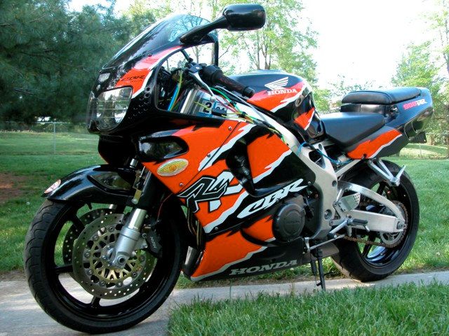
Magneto-Rheological Dampers for Super-sport Motorcycle Applications
John W. Gravatt

Abstract
In recent years, a flurry of interest has been shown for a relatively old technology called
magneto-rheological fluids, or MR fluids. Multiple types of devices have been designed
to implement this versatile fluid, including linear dampers, clutches, work-piece fixtures,
and polishing machines. The devices have been used in automobiles, washing machines,
bicycles, prosthetic limbs, and even smart structures.

This thesis focuses on another application of MR dampers, involving super-sport
motorcycles. This paper introduces the topics of MR dampers and motorcycle
suspensions, and why the two would be a good combination. A detailed history of MR
fluids, MR dampers, and motorcycle suspension technologies is given next.

After a broad outline of MR dampers and motorcycle suspensions, the method of
designing and manufacturing MR dampers is discussed. The damper design for this
research is presented in detail, along with the design procedure used to make it.

Next, laboratory testing for it is covered, including the test equipment, test procedure, and
the laboratory test results. Upon laboratory test completion, the field test setup and
procedure are presented. The results of field tests with stock dampers and MR dampers
with a variety of control systems is discussed.

The MR dampers provided a more stable ride than that of the OEM dampers. By
reducing suspension displacement, settling time, and suspension oscillations, the MR
dampers were able to reduce suspension geometry instability.

Lastly, concluding remarks are made on the research presented. Design flaws are
discussed, as well as recommendations for future work in the same area.

                                                                                           iv
Acknowledgements

I would like to thank Dr. Mehdi Ahmadian for helping me through my master’s studies at
Virginia Tech. Dr. Ahmadian was always an inspiration, no matter what bad news I had
to tell him about my research. I thank him for being patient with me when my timelines
did not hold true, and I will never forget his words of encouragement. Thanks so much
for welcoming me into the AVDL lab family.
       Thanks and love go to my family, who has supported me endlessly. To my
mother, Sarah, thank you for understanding and giving me support and love when I
needed it most. To my father, Mayo, thanks for the encouragement and support, and
putting your trust in me. To my brother, Carter, thanks for the advice about the road less
traveled, the one you have traversed before me, and thanks for all the supporting phone
calls. To my sister, Sally, be patient with the road ahead, life is what you make of it –
and good luck in your master’s studies. To my whole family – you’re the best family I
could have!
       I would like to give special thanks to Steve Grenoble and Fernando Goncalves.
Steve has been a lifesaver many times during assembly and testing, helping switch forks
and anything else that needed to be done. Thanks to Fernando for sacrificing his time to
help me do all of my laboratory testing. Thanks to all the AVDL members for our great
times at Claytor Lake – may life take you all on a fair and prosperous journey.
       Last but not least, I would like to acknowledge the support of Lord Corporation,
Material Division, in Cary, North Carolina for providing the MR fluid that was used in
this research.
       I would like to dedicate this research to my late grandfather, John R. Sutton,
affectionately known as Jack. An engineer and inventor, his strive to reach seemingly
impossible goals inspired me greatly.

                                                                                            iii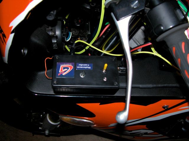
Contents

Chapter 1         Introduction.................................................................................................. 1
  1.1   OVERVIEW OF MOTORCYCLE SUSPENSIONS AND MR TECHNOLOGIES ............................................. 1
    1.1.1       A Brief History of Motorcycle Suspension Technologies........................................................ 1
    1.1.2       Magneto-rheological Fluids and Devices............................................................................... 2
    1.1.3       Magneto-rheological Damper Applications for Motorcycles ................................................. 3
  1.2   OBJECTIVES ...................................................................................................................................... 4
    1.2.1       Approach ................................................................................................................................ 4
    1.2.2       Outline .................................................................................................................................... 5
    1.2.3       Contributions .......................................................................................................................... 5

Chapter 2         Background .................................................................................................. 6
  2.1   MR FLUID......................................................................................................................................... 6
  2.2   MR DAMPERS ................................................................................................................................. 11
  2.3   MOTORCYCLE SUSPENSION TECHNOLOGY...................................................................................... 14
  2.4   LITERATURE SEARCH ...................................................................................................................... 17
    2.4.1       Keywords: magnetorheological motorcycle ........................................................................ 18
    2.4.2       Keywords: magneto-rheological motorcycle........................................................................ 18
    2.4.3       Keywords: magneto rheological motorcycle ....................................................................... 18
    2.4.4       Keywords: MR motorcycle................................................................................................... 19
  2.5   SUMMARY ....................................................................................................................................... 19

Chapter 3         Hardware Design and Fabrication........................................................... 20
  3.1   PRINCIPLES OF MR DAMPER DESIGN .............................................................................................. 20
    3.1.1       MR Damper Types ................................................................................................................ 20
    3.1.2       MR Damper Mathematics..................................................................................................... 23
    3.1.3       Electromagnet Design .......................................................................................................... 27
  3.2   MR DAMPER DESIGN FOR MOTORCYCLE APPLICATIONS ............................................................... 29
    3.2.1       Test Vehicle Overview .......................................................................................................... 29
    3.2.2       Analyzing the OEM Damper Package and Performance ..................................................... 30
    3.2.3       Designing the MR Damper ................................................................................................... 32
  3.3   CONTROL UNIT DESIGNS ................................................................................................................ 37
    3.3.1       On-Off Skyhook Control ....................................................................................................... 37
    3.3.2       Displacement-Based Control System.................................................................................... 40

Chapter 4         Hardware Laboratory Testing ................................................................. 43
  4.1   LABORATORY TEST PROCEDURE .................................................................................................... 43
  4.2   OEM DAMPER TESTING ................................................................................................................. 45

                                                                                                                                                          iv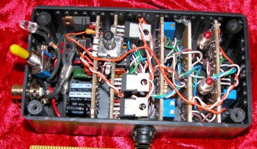
4.3     MR DAMPER TESTING .................................................................................................................... 46
   4.4     REMARKS ........................................................................................................................................ 54

Chapter 5            Hardware Field Testing ............................................................................ 55
   5.1     FIELD TEST SETUP .......................................................................................................................... 55
   5.2     PROCEDURE .................................................................................................................................... 58
   5.3     FIELD TEST RESULTS ...................................................................................................................... 60
       5.3.1       OEM Damper Results ........................................................................................................... 60
       5.3.2       MR Damper Results.............................................................................................................. 62
       5.3.3       Performance Comparison..................................................................................................... 68
   5.4     SUBJECTIVE OPINION OF THE TEST RIDER ...................................................................................... 70

Chapter 6            Conclusions................................................................................................. 72
   6.1     SUMMARY ....................................................................................................................................... 72
   6.2     RECOMMENDATIONS ....................................................................................................................... 75
       6.2.1       Damper Design..................................................................................................................... 75
       6.2.2       Prediction Model .................................................................................................................. 75
       6.2.3       Shaft Material & Design....................................................................................................... 76
       6.2.4       Housing Materials ................................................................................................................ 76
       6.2.5       Seals...................................................................................................................................... 77
       6.2.6       Coil Manufacturing .............................................................................................................. 77
       6.2.7       Control Units ........................................................................................................................ 78
       6.2.8       Control Sensors .................................................................................................................... 78
       6.2.9       Data Acquisition Units ......................................................................................................... 79

References ........................................................................................................................ 80

Vitae ................................................................................................................................. 82

                                                                                                                                                              v
List of Tables

TABLE 4.1. DAMPER FORCE CHARACTERIZATION DATA POINTS.................................................................. 44

                                                                                                                      vi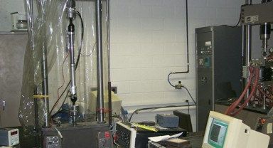
List of Figures
FIGURE 2.1. JACOB RAINBOW’S MR FLUID EXPERIMENT [2].......................................................................... 6
FIGURE 2.2. OFF-STATE MR FLUID PARTICLES (LEFT) ALIGNING IN AN APPLIED MAGNETIC
FIELD (RIGHT) [ADAPTED FROM 5].............................................................................................. 7
FIGURE 2.3. FERROUS PARTICLE CHAINS RESIST FLUID FLOW [ADAPTED FROM 5]......................................... 8
FIGURE 2.4. MR FLUID IN PRESSURE DRIVEN FLOW (VALVE) MODE [ADAPTED FROM 6]. ............................... 9
FIGURE 2.5. MR FLUID IN DIRECT-SHEAR MODE [ADAPTED FROM 6]............................................................ 10
FIGURE 2.6. MR FLUID IN SQUEEZE-FILM MODE [ADAPTED FROM 6]............................................................ 10
FIGURE 2.7. MR DAMPER OPERATING IN VALVE MODE. .............................................................................. 12
FIGURE 2.8. MR DAMPER USING BOTH VALVE AND SHEAR MODES. ............................................................. 13
FIGURE 2.9. MOTORCYCLE SUSPENSION GEOMETRY [ADAPTED FROM 7]..................................................... 15
FIGURE 2.10. BMW “TELELEVER” SUSPENSION SYSTEM [ADAPTED FROM 11]. .......................................... 17
FIGURE 2.11. LITERATURE SEARCH FLOWCHART. ........................................................................................ 18
FIGURE 3.1. MONOTUBE MR DAMPER, SECTION VIEW [ADAPTED FROM 5]................................................. 21
FIGURE 3.2. TWINTUBE MR DAMPER, SECTION VIEW [ADAPTED FROM 5]. .................................................. 22
FIGURE 3.3. DOUBLE-ENDED (THROUGH-TUBE) MR DAMPER, SECTION VIEW [ADAPTED FROM 5].............. 22
FIGURE 3.4. PRESSURE DRIVEN FLOW MODE. ............................................................................................... 24
FIGURE 3.5. DIRECT-SHEAR MODE. .............................................................................................................. 25
FIGURE 3.6. MR DAMPER DESIGN PROGRAM PART I................................................................................... 27
FIGURE 3.7. MR DAMPER DESIGN PROGRAM PART II. ................................................................................ 28
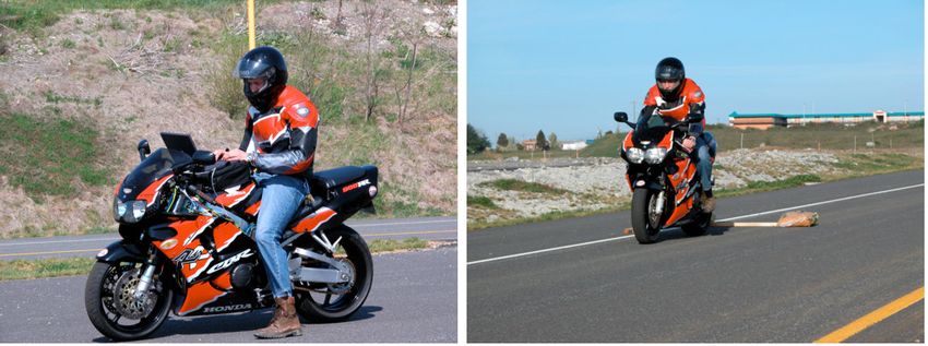
FIGURE 3.8. 1997 HONDA CBR900RR (LEFT) WITH OEM FORKS (RIGHT).................................................. 29
FIGURE 3.9. 1997 HONDA CBR900RR OEM DAMPER IN DAMPER DYNAMOMETER FOR
FORCE-VELOCITY CHARACTERIZATION..................................................................................... 30
FIGURE 3.10. 1997 HONDA CBR900RR OEM DAMPER CURVES (ZEROED DATA). ...................................... 31
FIGURE 3.11. OEM DAMPER ASSEMBLY. ..................................................................................................... 31
FIGURE 3.12. OEM DAMPER AND PREDICTED MR OFF STATE DAMPER CURVES. ......................................... 33
FIGURE 3.13. RETROFIT MR DAMPER MODULE MODEL (LEFT) AND PROTOTYPE (RIGHT)............................. 34
FIGURE 3.14. MODEL OF RETROFIT MR DAMPER COMPLETELY ASSEMBLED................................................ 34
FIGURE 3.15. RETROFIT MR DAMPER ASSEMBLY PROTOTYPE. .................................................................... 35
FIGURE 3.16. RETROFIT MR DAMPER ASSEMBLY, LABELED. ....................................................................... 35
FIGURE 3.17. SECTION VIEW OF MR DAMPER MODULE................................................................................ 35
FIGURE 3.18. NITROGEN CHARGER ASSEMBLY (LEFT) AND THE PROTOTYPE HARDWARE (RIGHT). .............. 36
FIGURE 3.19. SKYHOOK CONTROL SETUP [15].............................................................................................. 37
FIGURE 3.20. SKYHOOK CONTROL STRATEGY. ............................................................................................. 38
FIGURE 3.21. SKYHOOK CONTROL CIRCUITS. .............................................................................................. 39
FIGURE 3.22. SKYHOOK CONTROL UNIT. ..................................................................................................... 40
FIGURE 3.23. DISPLACEMENT CONTROL POLICY. ......................................................................................... 41
vii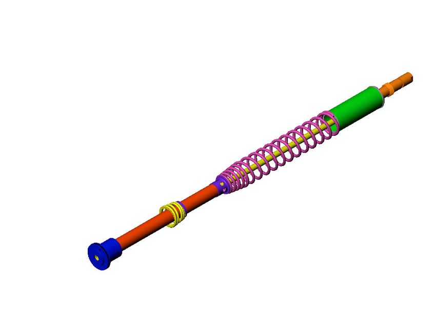
FIGURE 3.24. DISPLACEMENT CONTROL CIRCUIT BLOCK DIAGRAM............................................................ 41
FIGURE 3.25. DISPLACEMENT BASED CONTROL SYSTEM ON TEST VEHICLE. ................................................. 42
FIGURE 4.1. DAMPER DYNAMOMETER TEST FACILITY. ................................................................................. 43
FIGURE 4.2. DAMPER CURVE ZEROING EXAMPLE. ........................................................................................ 45
FIGURE 4.3. COMPLETE 1997 HONDA CBR900RR OEM DAMPER CURVE................................................... 46
FIGURE 4.4. FORCE VS. VELOCITY CURVE FOR MR DAMPER (180PSI). ......................................................... 47
FIGURE 4.5. EFFECT OF ACCUMULATOR PRESSURE ON SPRING FORCE. ......................................................... 48
FIGURE 4.6. MONOTUBE MR DAMPER OPERATING PROPERLY [ADAPTED FROM 5]....................................... 49
FIGURE 4.7. MR DAMPER CAVITATION CAUSED BY INSUFFICIENT ACCUMULATOR
                  PRESSURE [ADAPTED FROM 5]. .................................................................................................           50
FIGURE 4.8. FORCE VS. VELOCITY CURVE FOR MR DAMPER (100PSI). ......................................................... 51
FIGURE 4.9. THEORETICAL AND EXPERIMENTAL OFF STATE MR DAMPER CURVES. ..................................... 52
FIGURE 4.10. MR VS. OEM DAMPER COMPARISON. .................................................................................... 53
FIGURE 5.1. THE DATAQ DI-700 DATA ACQUISITION UNIT [ADAPTED FROM 16]. ...................................... 55
FIGURE 5.2. DATA ACQUISITION SYSTEM (LEFT) AND LAPTOP COMPUTER (RIGHT). ..................................... 56
FIGURE 5.3. SENSOR MOUNTING LOCATIONS................................................................................................ 57
FIGURE 5.4. INFRARED DATA STORAGE TRIGGER (LEFT) AND EMITTERS (RIGHT). ........................................ 58
FIGURE 5.5. TEST COURSE............................................................................................................................ 58
FIGURE 5.6. EQUIVALENT SUSPENSION INPUT GRAPH SHOWING SUSPENSION INPUT VERSUS
                  COURSE DISTANCE. ...................................................................................................................   59
FIGURE 5.7. DATA ACQUISITION SETUP (LEFT) AND VEHICLE TEST (RIGHT) ................................................. 59
FIGURE 5.8. TIME DOMAIN OEM SUSPENSION PERFORMANCE AT 15 MPH. .................................................. 61
FIGURE 5.9. FREQUENCY DOMAIN OEM SUSPENSION PERFORMANCE AT 15MPH. ........................................ 62
FIGURE 5.10. TIME DOMAIN PERFORMANCE OF MR SUSPENSION IN OFF-STATE AT 15 MPH. ........................ 63
FIGURE 5.11. FREQUENCY DOMAIN PERFORMANCE OF MR SUSPENSION IN OFF-STATE AT 15 MPH.............. 64
FIGURE 5.12. TIME DOMAIN PERFORMANCE OF MR SUSPENSION WITH SKYHOOK CONTROL AT 15 MPH. ..... 65
FIGURE 5.13. FREQUENCY DOMAIN PERFORMANCE OF MR SUSPENSION WITH SKYHOOK
                   CONTROL AT 15 MPH...............................................................................................................      66
FIGURE 5.14. TIME DOMAIN PERFORMANCE OF MR SUSPENSION WITH DISPLACEMENT
                   CONTROL AT 15 MPH...............................................................................................................      67
FIGURE 5.15. FREQUENCY DOMAIN PERFORMANCE OF MR SUSPENSION WITH DISPLACEMENT
                   CONTROL AT 15 MPH...............................................................................................................      68
FIGURE 5.16. FREQUENCY DOMAIN COMPARISON OF DISPLACEMENT DATA AT 15 MPH. .............................. 69
FIGURE 5.17. OEM AND MR DAMPER PERFORMANCE COMPARISON. .......................................................... 70
FIGURE 6.1. PERFORMANCE COMPARISON OF OEM AND MR DAMPERS...................................................... 74

                                                                                                                                                    viii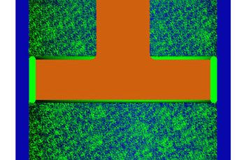
Chapter 1
Introduction

Since the introduction of the first motorcycle, suspension designers have sought to build
suspension systems that can provide both rider comfort and high-speed performance.
The purpose of this chapter is to inform the reader of traditional and current motorcycle
suspension technologies, and to provide a brief description of magneto-rheological (MR)
fluids and their use in new suspension technology. This research pertains to the use of
MR technologies in the evolving field of motorcycle suspension systems.

1.1 Overview of Motorcycle Suspensions and MR Technologies
Motorcycle suspension designers have historically sought a good compromise between a
comfortable ride and performance handling. Unfortunately, this comprise generally leads
to a suspension design that is good for a mix of performance and comfort, yet does not
excel at either of the two. Magneto-rheological suspension technologies offer a new
component for suspension design that can bridge this shortcoming.

1.1.1    A Brief History of Motorcycle Suspension Technologies
When the first motorcycle was manufactured by Daimler-Benz in 1885, suspension was
not a priority. Sporting iron-banded wooden wheels and a rigid chassis, the motorcycle
was nicknamed the “bone crusher” due to its lack of a comfortable ride [1]. The first type
of suspension introduced on motorcycles was a seat with springs underneath. Soon
motorcycle developers realized that a more useful suspension was in order for motorcycle
designs, and the emphasis of the development was placed on front suspension.
        Initially front suspension consisted of a sliding fork with springs. While boasting
more comfort than the original rigid fork design, the new suspension tended to oscillate
indefinitely because of its lack of damping capability. The decades between the 1920s
and 1940s saw an increase in motorcycle suspension designs; these included leading link
designs and frame mounted swing-arms [1]. With the addition of a damper, the simple

                                                                                            1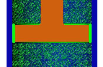
sliding sprung fork design proved to be the most robust motorcycle front suspension
design available.
        Most modern motorcycle suspensions are still based on a telescopic cartridge fork
design, which houses both the spring and damper unit. This design proved to be
lightweight, inexpensive, and sturdy enough to handle the loads of today’s motorcycles.
Damper technology, however, has continuously evolved. Monotube dampers have given
way to twintube dampers, while fixed orifice damper valving has been replaced by rider-
adjustable compression and rebound adjusters. The end goal has been to provide the
rider with better ride performance while maintaining comfort.

1.1.2   Magneto-rheological Fluids and Devices
In recent years, a family of fluids known as magneto-rheological fluids has gained
increased recognition for its many applications. Magneto-rheological fluids (referred to
as “MR” fluids) demonstrate a change in apparent viscosity when exposed to a magnetic
field. Jacob Rainbow, an inventor at the US National Bureau of Standards, developed the
first MR fluids in the late 1940s [2]. Upon introduction, there was keen interest in the
technology for devices like automatic transmissions and clutches, but the activity dropped
off shortly thereafter. Resurgence in interest in MR fluids occurred in the early 1990s
when Dave Carlson of Lord Corporation began to experiment with the fluid for a variety
of devices, including vehicle suspensions.
        Jacob Rainbow’s original MR fluids consisted of nine parts by weight of carbonyl
iron to one part of a carrier fluid, namely silicon oil or hydrocarbon-based oil. To
increase the fluid stability and reduce settling, grease or another thixotropic solution was
added [2]. This original solution proved to be as strong as modern day MR fluids.
Modern fluids use micron sized iron particles coated with an anticoagulant in a carrier
fluid of hydrocarbon-based oil, silicon-based oil, or water. The fluids also contain a
number of anti-settling agents to prevent the fluid from hardening [2].
        Magneto-rheological fluids are activated by the application of a magnetic field
across the fluid. The induced field causes alignment of the iron particles in column-type
structures parallel to the field lines [3]. This resulting structure resists fluid flow, causing
a change in fluid apparent viscosity. While the viscosity of the carrier fluid does not

                                                                                               2
actually change, the shear strain rate and yield stress of the fluid increase with an
increasing field [3]. This variable MR fluid yield stress is advantageous in applications
such as dampers and shock absorbers.
Recent renewed interest in MR fluids has been apparent in automobile suspension
technologies. Lord Corporation pioneered the use of the fluid in the 1990s, introducing a
MR damper for truck seat suspension called the “Motion Master.” Shortly after, Lord
developed a rotary MR brake for treadmill applications, as well as dampers for
automobile use. Current manufacturers of MR dampers include Lord Corporation,
Delphi, and Carrera Shocks, Inc. Cadillac and Corvette models introduced an electronic
ride control system in 2003, which boasted the use of MR dampers [17].
1.1.3 Magneto-rheological Damper Applications for Motorcycles
MR technology offers excellent properties that can be utilized in motorcycle suspension
design. Changing fork fluid viscosity is one of the most popular ways to tune a
motorcycle suspension. With a MR damper system, changing the fluid viscosity is
accomplished by adjusting the magnetic field intensity. The range of adjustability is
virtually infinite within the off state and saturation state, making MR damper
technologies an excellent replacement for conventional motorcycle front suspension
dampers. While MR dampers are becoming common in automobile primary suspensions,
motorcycle applications are rare.
MR technologies are not limited to simple rebound and compression adjustments
though. Utilizing proper control techniques, such as a skyhook or groundhook control
methods, MR dampers can drastically increase the damper’s efficiency by reacting to
road inputs and minimizing suspension oscillation [13]. Use of MR dampers with an
effective control policy allows the suspension to offer both comfort and performance in
the same package. Motorcycle suspension performance no longer needs to be hindered
by compromise between comfort and performance—adaptive control techniques like
skyhook control can offer the great performance and great comfort at the same time.
31.2 Objectives
The primary objectives of this research are to:
1. research the MR damper designs to adapt for use in motorcycle front
suspensions,
2. design and manufacture retrofit MR damper modules for a motorcycle front
suspension,
3. design and manufacture control circuits to operate the MR damper
replacements,
4. test the MR damper replacements and control circuit in laboratory and field
testing,
5. provide an analysis of the effectiveness of MR dampers for motorcycle
applications, and
6. provide recommendations for future design and manufacture of MR dampers
for motorcycle applications.
1.2.1 Approach
This research focuses on the design and manufacture of MR dampers and control circuits
for use in motorcycle front suspensions. A monotube design was chosen for the MR
dampers to replace the vehicle’s original equipment manufacturer (OEM) passive
twintube dampers. The dampers were manufactured in house and subjected to laboratory
dynamic testing to determine the MR damper curves, which were then compared to the
OEM suspension damper curves.
Three control circuits were designed and built for field-testing. The first design
was a simple DC power supply for the initial ride on the new system. The second design
was an analog skyhook control system that utilized accelerometer inputs from the
vehicle’s wheel and body. The skyhook control system determined both the absolute
velocity of the body and the relative velocity of the damper to regulate the damper
between its full on and off states. The third control system design was a displacement
based control design which used high damping for small displacements, low damping for
large displacements, and high damping for a bottoming prevention measure. All control
4system designs were field tested to determine their effectiveness for a motorcycle front
suspension technology.
1.2.2 Outline
Chapter 2 contains background information on the history and uses of MR fluids, current
and previous MR dampers and damper designs, and current motorcycle suspension
technology. Current and previous work on MR dampers with applications in motorcycle
suspension will also be discussed. Chapter 3 discusses the design and fabrication of the
MR dampers and control circuits used in this research. Chapter 4 discusses hardware
testing techniques, test setup, and test results for all laboratory testing. Chapter 5
includes testing techniques, test setup, and test results for all field-testing. Chapter 6
summarizes the work done discussed in this paper as well as recommendations for future
design and testing of MR dampers for motorcycle front suspensions.
1.2.3 Contributions
The research discussed in this paper will be a great contribution to the motorcycle
industry. MR damper technologies would be a great advance in current motorcycle
suspension systems, offering greater ease of adjustment, damper adjustment on-the-go,
and the possibility of great comfort combined with excellent performance in the same
package. Semiactive suspension systems will provide a base for the next generation of
motorcycle suspension systems.
5Chapter 2
Background
This chapter explains in detail the technical background of MR fluids, their use in MR
dampers, and some commercially available MR dampers. Motorcycle suspension
technologies will be examined, highlighting some of the problems with modern
motorcycle suspension systems. Current and previous research related to the application
of MR dampers on motorcycles will be discussed in the literature review.
2.1 MR Fluid
Magneto-rheological fluids are fluids that exhibit a change in rheological properties when
a magnetic field is induced through the fluid [3]. In essence, the fluid’s flow
characteristics, namely apparent viscosity, change. Jacob Rainbow, who worked for the
US National Bureau of Standards, first introduced MR fluids in the 1940s [3]. In an early
demonstration, Rainbow was able to suspend a 117 pound woman from a swing using the
activated fluid, as shown in Figure 2.1 [2]. This experiment proved the strength and
FIGURE 2.1. JACOB RAINBOW’S MR FLUID EXPERIMENT [2].
6capabilities of the new MR fluid. For this experiment to succeed, the fluid’s yield
strength needed to be over 100 kPa.
Initially MR fluids drew significant interest in the 1940s and early 1950s, but
soon the new technology lost popularity [3]. In the early 1990s, Lord Corporation
pioneered the use of MR fluids in the Motion Master™ Damper and began improving the
MR solution characteristics.
MR fluids are quite similar to electrorheological (ER) fluids and ferrofluids in
composition: all three fluids are a non-colloidal suspension of polarizable particles [4].
While MR and ER fluids usually contain carbonyl iron on the order of a few microns in
size [3], ferrofluids use nanometer-sized iron oxide particles. Ferrofluid particles are too
small to demonstrate any yield strength; instead they tend to be only attracted to and flow
toward a magnetic field. MR fluids, on the other hand, demonstrate very high yield
strengths when a field is induced, usually on the order of 20 to 50 times the strength of
ER fluids [4].
With no applied magnetic field (off state), MR fluids behave with Newtonian-like
characteristics [6]. Applying an external magnetic field through the fluid activates MR
fluids, causing the micron-sized particles to form magnetic dipoles along the lines of
magnetic flux, as shown in Figure 2.2.
FIGURE 2.2. OFF-STATE MR FLUID PARTICLES (LEFT) ALIGNING IN AN APPLIED MAGNETIC
FIELD (RIGHT) [ADAPTED FROM 5].
The dipoles align parallel to the induced magnetic flux lines to form chain-like
structures of iron particles between the north and south pole [6]. The ferrous particles
7that form each of the chains resist movement out of their respective flux lines, and the
amount of resistance is proportional to the intensity of the applied magnetic field. The
reluctance of the ferrous dipole chains to move result in a restriction of the fluid flow, as
seen in Figure 2.3.
FIGURE 2.3. FERROUS PARTICLE CHAINS RESIST FLUID FLOW [ADAPTED FROM 5].
The flow restriction resulting from the alignment of the ferrous dipoles causes a
change in the apparent viscosity of the fluid. The term “apparent” is used to modify the
fluid because the carrier fluid’s physical viscosity does not change – rather, the MR
mixture acts as if it is thickening due to the resistance of the dipole chains. The apparent
viscosity can be varied infinitely between its off-state and saturation state, even becoming
a near-solid. At saturation, the ferrous dipoles are fully aligned and any additional field
intensity will cause no change in the apparent viscosity [5].
MR fluid also develops a yield stress as it thickens, based on the amount of
mechanical energy required to yield the ferrous dipole chains. This behavior can be
compared to a Bingham plastic with variable yield strength [3].
MR fluids can be used in three principal modes of operation: pressure driven
flow (valve) mode, direct-shear mode, and squeeze-film mode [6]. In pressure driven
flow (valve) mode, the two magnetic poles are fixed, and a pressurized flow of MR fluid
moves between them. In direct-shear mode, the two magnetic poles move relative to
each other, and the MR fluid is “sheared” between them. Squeeze-film mode involves a
layer of MR fluid which is squeezed between the two magnetic poles [6].
8Pressure driven flow mode, commonly known as valve mode, has two fixed
magnetic poles through which pressurized MR fluid flows, as shown in Figure 2.4. Upon
application of a magnetic field, the MR particles align parallel to the applied field lines
and resist the flow of the pressurized MR fluid [5, 6]. The name “valve mode” is
commonly used since, in the essence, this mode resembles the operation of a valve. Via
the application of higher intensity fields, the flow resistance increases, much like closing
a sink faucet valve. The pressure driven flow mode is probably the most common mode
used in MR dampers, such as Lord Corporation’s “MR Damper” (RD-1005-3), but can be
other applications in which a variable flow resistance is required.
Applied Field Lines
Negative Pole Plate
Pressurized Fluid Flow
MR Fluid Flow
Positive Pole Plate
FIGURE 2.4. MR FLUID IN PRESSURE DRIVEN FLOW (VALVE) MODE [ADAPTED FROM 6].
Operation in direct-shear mode requires that the two magnetic pole plates move
relative to each other, thus “shearing” the fluid between them, as depicted in Figure 2.5.
An applied magnetic field aligns MR particles perpendicular to the pole plates while the
shearing motion attempts to bend the particle chains along the flux lines [5, 6]. Again, as
the field intensity increases, the MR fluid’s resistance to shearing increases. The direct-
shear mode of MR fluids can be used in low force dampers, and has also found uses as
magnetic brakes and clutches, such as Lord Corporation’s “MR Rotary Brake” (MRB-
2107-3).
9Applied Field Lines
Negative Pole Plate
Force Rel. Velocity
Force MR Fluid
Positive Pole Plate
FIGURE 2.5. MR FLUID IN DIRECT-SHEAR MODE [ADAPTED FROM 6].
Squeeze-film mode, the third mode of MR fluid use, is used via squeezing the two
magnetic pole plates together on a thin film of MR fluid, as shown in Figure 2.6. The
application of force on the plates parallel to the direction of flux lines pressurizes the
chain-like structures of MR fluid particles. The intensity of the induced field determines
the ability of the MR fluid particle columns to resist buckling.
Applied Field Lines
Force
Negative Pole Plate
MR Fluid
Positive Pole Plate
Force
FIGURE 2.6. MR FLUID IN SQUEEZE-FILM MODE [ADAPTED FROM 6].
The adjustability of the MR fluid is heavily dependent on the size of the fluid gap
in each of the fluid’s operation modes. The fluid gap for the direct-shear and squeeze-
film modes should be in the range of 0.005 inch to 0.025 inch, for most vehicle damper
applications. The fluid gap for pressure driven flow mode depicted in Figure 2.5 should
10also be between 0.005 inch and 0.025 inch [5]; however, a different orifice type (i.e.,
circular orifice) would have to be designed around the volume of the fluid being
activated. A smaller fluid gap requires less field intensity and therefore less power to
operate. This aspect is an important part of designing MR fluid devices.
Currently, Lord Corporation is the leading producer of MR fluids and devices. In
early research, Lord Corporation discovered a new, undesirable property of MR fluids
that had not been found in Jacob Rainbow’s early work. Some initial fluids used in
prototype dampers were subject to “in-use thickening (IUT),” which caused the damper’s
off state force versus velocity curve to gradually increase through out its cyclic lifetime,
600,000 cycles at the time [2]. The force vs. velocity curve increased as much as 250%
in some cases. The IUT phenomenon was caused by the iron particles shearing into
smaller, nanometer-sized particles, which increased the viscosity of the fluid. Through
two years of development, Lord Corporation was able to virtually eliminate the problem
of IUT, and new fluids are capable of over 10 million cycles with a negligible amount of
IUT [2].
The Lord Corporation offers four variations of MR fluid: two types of
hydrocarbon-based oils, a silicon-based oil, and a water-based fluid. Lord adds a
proprietary mixture of wear and abrasion inhibitors as well as anti-coagulants to ensure
good functionality throughout the life of the fluid [4].
2.2 MR Dampers
Magneto-rheological dampers are perhaps one of the most common applications for MR
fluids. The fluid’s adjustable apparent viscosity makes it ideal for use in dampers for
vibration control. Real-time adjustable systems can be developed to change damping
based on certain physical measurements, such as velocity or acceleration, in order to
better counteract and control the system dynamics.
Typically, MR damper applications use the pressure driven flow (valve) mode of
the fluid, or a combination of valve mode and direct-shear mode. Dampers that use only
direct-shear mode tend to be used in applications that do not require much force from the
damper.
11In a typical pressure driven flow mode damper, either the movement of the piston
assembly, the accumulator charge, or a combination of both pressurizes the MR fluid. As
the fluid flows through the valve, the coils can be powered, causing activation regions
where the fluid has been polarized, as shown in Figure 2.7.
Paramagnetic
Stainless Steel Pole (Fixed to Activation Regions
Weld Bead Coil Assembly)
Damper Electromagnetic
Housing Coils Fluid Gap
FIGURE 2.7. MR DAMPER OPERATING IN VALVE MODE.
Lord Corporation’s Motion Master damper is similar to the damper shown in
Figure 2.7. Instead of using the housing as the second paramagnetic pole, a small sleeve
is attached to the coil via stainless steel welds, which prevent a magnetic short between
the two poles. As the coil assembly moves, the fluid in the direction of travel is
pressurized, and flows through the coil/valve assembly, where it can be activated by the
electromagnetic coils. Increasing field strength produces stronger MR particle chains
between the two poles of the field, creating a higher resistance to the flow of the MR
fluid through the valve section of the damper. This resistance provides the force
mechanism for the damper. The flow resistance can be regulated between the off state
(no applied field) and the saturation state, at which point the particles are fully aligned
and an increase in the electromagnet current fails to produce a higher damper force at a
certain velocity [5].
12MR dampers can also use a combination of the pressure driven flow and direct-
shear modes of the MR fluid operation. In this case, the damper housing is used as the
second paramagnetic pole, and the coil assembly moves relative to the damper housing,
as shown in Figure 2.8. The fluid flows through the fluid gap between the damper
housing and the coil assembly, where it can be activated by the coils. While the fluid is
primarily operating in pressure driven flow mode, the relative velocity between the two
pole plates leads to a direct-shear mode of operation as well.
Activation Regions Piston Guide
Fluid Gap Electromagnetic Magnetic Flux Damper
Coils Lines (Approx) Housing
FIGURE 2.8. MR DAMPER USING BOTH VALVE AND SHEAR MODES.
The magnetic flux lines illustrated in Figures 2.7 and 2.8 do not represent the
actual flux lines of the magnetic field. Since the coil assembly and the housing are made
of low reluctance iron, the fluid gap has the highest reluctance of the magnetic circuit.
Therefore, the flux lines will probably be normal to the flow of the fluid, as opposed to
the angled flux path across the fluid gap demonstrated. Since the fluid is the highest
reluctance component of the magnetic path, the fluid gap has tremendous impact on the
effectiveness of the coil to control the fluid.
132.3 Motorcycle Suspension Technology
From the introduction of the world’s first motorcycle in 1885 until the early 1900s,
suspension for motorcycles was little more than a squishy tire and a driver seat with
springs [1]. Suspension design as it seems, was merely an afterthought. With the
conditions of early roads and a rigid frame, motorcycle riders were punished while riding
their new motorcycles.
As technology grew, one of the primary focuses of improvement became the front
suspension. While the driver was supported by a comfortable, sprung leather seat, the
handlebars would thrash any rider upon hitting a bump or pothole in the road. In order to
reduce the road inputs through the handlebars, motorcycle designers introduced springs
into the front forks, making the first version of a telescoping fork. Simple springs for a
front suspension proved to be rather inadequate, since the suspension would oscillate
uninhibited after being excited by road input.
Motorcycle designers began struggling with damping the front suspension
systems and introduced a number of systems to work this task. One of the earliest sprung
and damped front motorcycle suspensions was known as the girder fork. Original girder
fork designs used a leading link type of suspension, and was one of the earliest attempts
to control the front suspension of a motorcycle. This design included a spring was
mounted between the leading link and the motorcycle frame, and a friction damper which
was stiff at the beginning of its travel, and softer with greater suspension travel. Leading
link designs were simply a hinged carrier that carried the front wheel [1]. Girder forks
proved to be unstable at higher speeds though, since the front wheel’s motion was that of
an arc, thereby changing the effective wheelbase of the motorcycle throughout its range
of suspension travel [1].
BMW introduced the hydraulic damper for the conventional telescoping forks in
1935 [8]. Hydraulic dampers were far superior to the friction dampers used in leading
link designs, such as the girder fork, and proved to have an almost opposite operation
from the friction dampers. The new hydraulic dampers were soft and supple at the
beginning of their stroke, but as velocity increased, their damping rate increased
correspondingly. The BMW design started the trend of using damped telescoping forks
for the front suspension, a design that is still the most common form of motorcycle front
14suspension today. Many other motorcycle designers followed suit: Norton released a
similar design in 1939, followed by the introduction of the Matchless design in 1941, and
Ariel’s design in 1941 [10].
Refinements to the BMW damped telescoping fork have led to today’s
conventional fork designs. Modern designs offer plusher rides and better performance
through progressive spring rates, adjustable spring pre-load, adjustable rebound and
compression damping, reduced sliding friction, and new material technology that allows
lighter forks with increased rigidity. These forks, however, are still reminiscent of the
original BMW design of 1935.
While the damped telescoping fork provides substantially improved front
suspension performance, there are many drawbacks to the design. Telescoping forks
possess an unwanted characteristic known to motorcycle suspension designers as stiction,
or binding. The fork tubes have a rake angle, which is the angle between the forks and
the vertical axis, as shown in Figure 2.9. Longitudinal forces acting on the wheel attempt
to bend the fork tubes, and the bending causes the fork sliders to bind on each other,
which is the cause of stiction in the slider bushings [8].
FIGURE 2.9. MOTORCYCLE SUSPENSION GEOMETRY [ADAPTED FROM 7].
15The rake and trail shown in Figure 2.9 are also an important factor in stability.
The trail (also known as castor) helps to keep the motorcycle in a straight line by
counteracting lateral turning forces and maintaining directional stability [7]. This
suspension geometry can also lead to instability in cornering. As the suspension
compresses, the front of the motorcycle dives as the rear rises, causing the rake
dimension to change. When the rake changes, so does the trail length, causing a
subsequent shift in the amount of aligning torque. The shift in aligning torque is
transmitted to the rider who has to stabilize the bike through the feedback from the
handlebars. This process can lead to tire wobble, which is the beginning of a high speed,
uncontrollable shift of the steering from lock to lock, usually resulting in a dismount.
Further complaints of telescoping fork designs include their inability to separate
braking forces and road inputs, resulting in tremendous dive under braking [8].
Additionally, telescoping fork designs tend to experience “chatter,” or small suspension
oscillations on the order of two or three Hertz. Though chatter can usually be tuned out,
it is uncomfortable for the rider and can also lead to instability in cornering.
Motorcycle suspension designers have successfully tackled some of the problems
in telescoping front suspension in recent years. For example, the traditional forks with a
the stanchion tube on the top have given way to inverted or “upside-down” forks, where
the stanchion tube mounts to the wheel. This design significantly increases the fork
rigidity and also reduces stiction, two of the main problems of traditional telescoping
forks. New forks have more precise rebound and compression adjustments to allow a
rider to customize the suspension for the rider’s size and weight, as well as riding style.
Newer and more innovative front suspension designs have been few and far
between. BMW recently introduced the “Telelever” system, which uses a pair of forks to
guide the wheel, but uses a nitrogen-charged monotube shock to control the wheel’s
motion. The shock is mounted to the frame at one end and a leading link A-arm at the
other, allowing the shock to transmit the braking forces into the frame, rather than the
handlebar [1]. The design, illustrated in Figure 2.10, has received significant praise for
its stability and anti-dive capability, allowing riders to brake harder and later when
beginning cornering [8].
16Nitrogen Charged Sliders Leading Link
Mono Tube Shock A-arm
FIGURE 2.10. BMW “TELELEVER” SUSPENSION SYSTEM [ADAPTED FROM 11].
2.4 Literature Search
The following literature search was conducted to determine the current and previous
research pertaining to magneto-rheological dampers in motorcycle suspension
applications. Five databases were used in this literature search: the Applied Science and
Technology Index, the Compendex database, the Engineering and Technology database,
the LexisNexis Academic database, and the Transportation Research Information Service
(TRIS) database. Primarily focusing on motorcycle applications of magneto-rheological
fluid and damper technology, this search returned few results. Each database was
searched for a variety of different phrases: “magneto-rheological [and] motorcycle,”
“magneto-rheological [and] motorcycle,” “magneto rheological [and] motorcycle,” and
“MR [and] motorcycle.” Only one database, the Engineering and Technology database,
returned results. The search results primary database, Engineering and Technology, are
shown in Figure 2.11.
17Magnetorheological Magneto- Magneto MR
(210) Rheological (59) Rheological (40) Motorcycle (50)
Magnetorheological Magneto- Magneto
Motorcycle (0) Rheological Rheological
Motorcycle (2) Motorcycle (2)
FIGURE 2.11. LITERATURE SEARCH FLOWCHART.
2.4.1 Keywords: magnetorheological motorcycle
While the keyword “magnetorheological” produced copious results, no results were
related to the use of magnetorheological devices in motorcycle applications.
2.4.2 Keywords: magneto-rheological motorcycle
This search returned two results. Though both papers were based on magneto-
rheological damper applications for off-road motorcycles, only one was available for
viewing.
Erickson and Gordaninejad [12] discuss a theoretical model for the damping force
of a MR damper and predict the force vs. displacement curve for the damper. The
predicted results are then compared experimental force vs. displacement results of a
modified Honda XR 400 off-road motorcycle rear shock absorber. The main purpose of
the model was to validate the theoretical force vs. displacement model. No field tests
were conducted in this research.
Peck [13] also researches the application of MR dampers for off-road motorcycle
use. This thesis, however, was not available in its full form, as only its listing was given.
2.4.3 Keywords: magneto rheological motorcycle
This search returned two results, both identical to those found in the search for keywords
“magneto-rheological motorcycle” in 2.4.2. No new results were found.
182.4.4 Keywords: MR motorcycle
This search produced 50 results, none of which were related to magneto-rheological
dampers or the application of MR dampers to motorcycle technology.
2.5 Summary
Past research on magneto-rheological fluids for use in vehicle primary suspension
systems has eluded motorcycles. Erickson researched using MR fluid in a rear shock
absorber of an off-road motorcycle, but the research was focused on making and
verifying a model of the MR damper’s force versus displacement characteristics, and
involved no field testing.
The author intends to complete this void by designing and building prototype MR
dampers for a motorcycle front suspension, and then test the dampers against the OEM
dampers in laboratory and field tests. The goal of the research is to determine the
performance gains of a semiactive MR front suspension over the OEM system.
19Chapter 3
Hardware Design and Fabrication
Magnet-rheological dampers are used for a variety of different applications ranging from
automobile primary suspensions to smart structure vibration control. The popularity of
these dampers has led to extensive research and development to produce very
controllable dampers with long life spans.
The primary goal of the damper design in this research was to retrofit MR
dampers into the OEM stanchion tubes. Motorcycle fork dampers are typically very thin
diameter, with a body diameter of approximately one inch or less. This size constraint
causes a packaging issue with the MR damper module itself.
In this chapter, the principles of design of the MR dampers, including the types of
MR dampers, the mathematics involved with damper design, and the design of the
electromagnetic circuit, will be discussed. Packaging issues will be considered, and the
final design selected for the motorcycle application will be presented in detail.
3.1 Principles of MR Damper Design
Magneto-rheological damper design requires knowledge of fluid dynamics,
electromagnetic principles, and basic machine design. The purpose of this section is to
describe the guidelines of designing and manufacturing MR dampers.
3.1.1 MR Damper Types
MR dampers are much like conventional fluid dampers in basic construction, but the
conventional damper valves are replaced with an electromagnetic coil to control the MR
fluid behavior.
Linear MR dampers can be of three primary designs: monotube, twintube, or
double-ended (also known as through-tube). The three design types reflect methods of
adjusting the fluid volume to account for the volume of the damper shaft. Monotube
20designs are the most common damper design; they exhibit simplicity and compactness of
design and with the ability to be mounted in any orientation [5].
The monotube damper is composed of a main damper housing, a piston and piston
rod assembly, and an accumulator, as shown in Figure 3.1. The main reservoir contains
the piston and piston rod assembly submersed in the MR fluid, while the accumulator
reservoir contains a compressed, non-oxidizing gas (usually nitrogen) [5]. As the piston
rod moves into the damper housing, a volume of fluid equivalent to the volume of the
intruding piston rod is displaced. The accumulator piston moves toward the bottom of
the damper, compressing the nitrogen charge to account for the change in volume. As the
piston rod retracts, the accumulator piston moves up the damper tube to counteract the
loss of volume. The monotube damper design is the most versatile damper design since it
can be mounted in any orientation without affecting the damper’s performance.
Main Reservoir
Piston Guide Compressed Gas
Reservoir
Piston
Piston Rod Accumulator Piston
FIGURE 3.1. MONOTUBE MR DAMPER, SECTION VIEW [ADAPTED FROM 5].
The twintube damper uses inner and outer cartridges to negotiate the changing
volume of MR fluid, as shown in Figure 3.2. As the piston rod enters the inner housing,
the extra volume of MR fluid displaced by the piston rod is forced from the inner housing
to the outer housing via the foot valve. When the piston rod retracts, MR fluid flows
back into the inner housing, therefore preventing the creation of vacuum in the inner
housing and cavitation of the damper. Drawbacks of this design include size and
orientation – this damper must be mounted with the foot valve at the bottom to ensure no
cavitation.
21Piston Guide Foot Valve
Piston
Piston Rod
Outer Housing Inner Housing
FIGURE 3.2. TWINTUBE MR DAMPER, SECTION VIEW [ADAPTED FROM 5].
Double-ended (through-tube) dampers use a third method to account for the
piston rod volume. Fully extended, the piston rod protrudes through both sides of the
damper housing, as shown in Figure 3.3. This method of damper design retains a
constant piston rod and fluid volume within the housing, thereby eliminating the need for
a second housing or accumulator.
Damper Housing
Rear Piston Rod
Front Piston Rod
Piston Fluid Reservoir
FIGURE 3.3. DOUBLE-ENDED (THROUGH-TUBE) MR DAMPER, SECTION VIEW [ADAPTED FROM 5].
The twintube and double-ended damper provide a significant advantage over the
monotube design. The pressurized charge in the accumulator of the monotube design
adds a spring force to the damping rod, so not only does the damper have force vs.
22You can also read