Finlandia Seaways the ro-ro cargo vessel - Serious Marine ...
←
→
Page content transcription
If your browser does not render page correctly, please read the page content below
ACCIDENT REPORT

                                  Report on the investigation of
                               the engine failure and fire on board
                                       the ro-ro cargo vessel

                                    Finlandia Seaways
                               resulting in injury to one crewman
                                    11 miles east of Lowestoft
                                            16 April 2018

                  SERIOUS MARINE CASUALTY       REPORT NO 2/2021      FEBRUARY 2021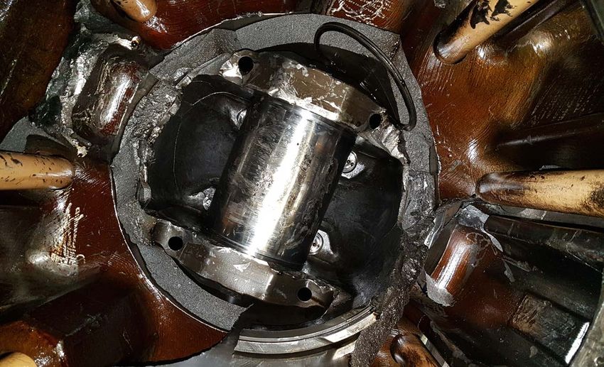
The United Kingdom Merchant Shipping

                          (Accident Reporting and Investigation)

                             Regulations 2012 – Regulation 5:

“The sole objective of the investigation of an accident under the Merchant Shipping (Accident
Reporting and Investigation) Regulations 2012 shall be the prevention of future accidents
through the ascertainment of its causes and circumstances. It shall not be the purpose of an
investigation to determine liability nor, except so far as is necessary to achieve its objective,
to apportion blame.”

                                             NOTE
This report is not written with litigation in mind and, pursuant to Regulation 14(14) of
the Merchant Shipping (Accident Reporting and Investigation) Regulations 2012, shall be
inadmissible in any judicial proceedings whose purpose, or one of whose purposes is to
attribute or apportion liability or blame.

© Crown copyright, 2021

You may re-use this document/publication (not including departmental or agency logos) free of
charge in any format or medium. You must re-use it accurately and not in a misleading context.
The material must be acknowledged as Crown copyright and you must give the title of the source
publication. Where we have identified any third party copyright material you will need to obtain
permission from the copyright holders concerned.

All MAIB publications can be found on our website: www.gov.uk/maib

For all enquiries:
Marine Accident Investigation Branch
First Floor, Spring Place
105 Commercial Road
Southampton
SO15 1GH                                                    Email:          maib@dft.gov.uk
United Kingdom                                              Telephone: +44 (0) 23 8039 5500

Press enquiries during office hours: 01932 440015
Press enquiries out of hours: 020 7944 4292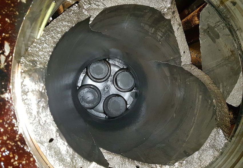
CONTENTS
GLOSSARY OF ABBREVIATIONS AND ACRONYMS

SYNOPSIS                                                                 1

SECTION 1 - FACTUAL INFORMATION                                          2

1.1    Particulars of Finlandia Seaways and accident                      2
1.2    Narrative                                                          3
       1.2.1 Passage from Zeebrugge                                       3
       1.2.2 The engine failure and subsequent fire                       3
       1.2.3 Emergency response                                           4
       1.2.4 Engine room fire damage                                     12
1.3    Crew                                                              12
1.4    Environmental conditions                                          13
1.5    Finlandia Seaways13
1.6    Main engine                                                       13
       1.6.1 Overview                                                    13
       1.6.2 Engine design and key components                            14
       1.6.3 Engine condition monitoring and protection systems          16
       1.6.4 Post-fire inspection                                        17
       1.6.5 Engine room alarms                                          21
       1.6.6 Planned maintenance                                         21
       1.6.7 Outsourcing of main engine work                             22
1.7    Diesel Service Group UAB                                          22
       1.7.1   Overview                                                  22
       1.7.2   Certification                                             22
1.8    Connecting rod piston pin bush renewal                            23
       1.8.1 MAN guidance and procedure                                  23
       1.8.2 Diesel Service Group guidance and procedure                 24
1.9    Engine manufacturer’s post-failure engine inspection and guidance 27
       1.9.1   Engine inspection and failure mode analysis               27
       1.9.2 Botnia Seaways31
       1.9.3 Engine design modifications and updates                     33
1.10   Metallurgical analysis                                            33
1.11   External oversight                                                34
1.12   Emergency response                                                36
       1.12.1 Carbon dioxide fixed fire-extinguishing system             36
       1.12.2 Means of escape                                            37
       1.12.3 Emergency escape breathing devices                         39
       1.12.4 Voyage data recorder recovery                              40
1.13   Previous/similar accidents                                        40
       1.13.1 Thetis D40
       1.13.2 Power station, Spain                                       41

SECTION 2 - ANALYSIS                                                    42

2.1 Aim                                                                 42
2.2 Accident overview                                                   42
2.3 Engine failure                                                      42
    2.3.1 Sequence of events                                            42
    2.3.2 Identification of the component failure                       43
    2.3.3 Failure mode                                                  43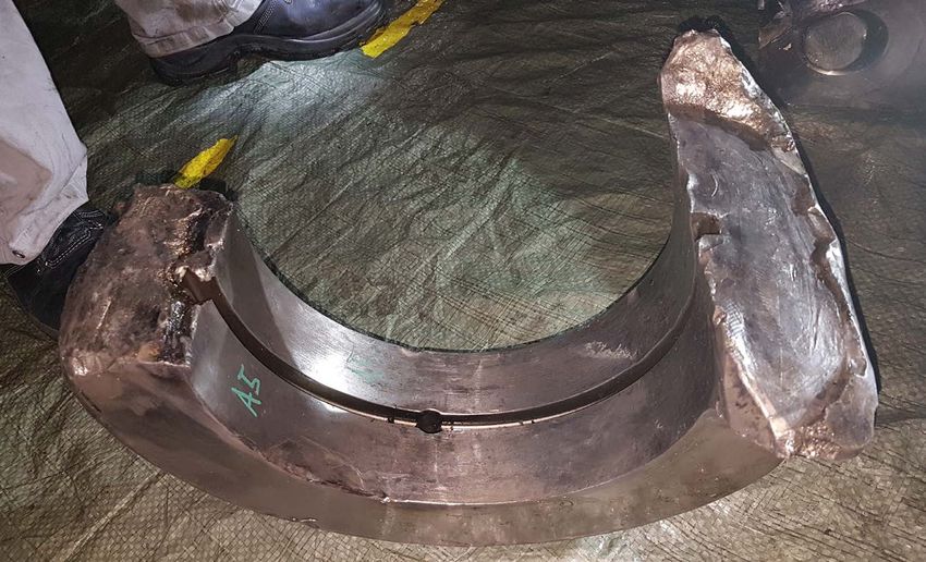
2.4 Fracture mechanism                                                                 44
    2.4.1 General                                                                      44
    2.4.2 Fatigue fracture                                                             44
    2.4.3 Notch effect and toughness                                                   44
    2.4.4 Localised heating                                                            46
    2.4.5 Inspection and analysis                                                      47
2.5 Maintenance management                                                             47
    2.5.1 Overview                                                                     47
    2.5.2 Connecting rod small end overhaul process                                    48
    2.5.3 Rotation of connecting rod small ends                                        48
    2.5.4 Diesel Service Group quality control                                         49
    2.5.5 DFDS quality control                                                         50
    2.5.6 Classification Society oversight                                             50
2.6 Emergency response                                                                 51
    2.6.1 Overview                                                                     51
    2.6.2 Carbon dioxide bottle identification                                         51
    2.6.3 Effective numbers and distribution of EEBDs                                  52
    2.6.4 VDR                                                                          52

SECTION 3 - CONCLUSIONS                                                                53

3.1 Safety issues directly contributing to the accident that have been addressed or
    resulted in recommendations                                                        53
3.2 Safety issues not directly contributing to the accident that have been addressed
    or resulted in recommendations                                                     54
3.3 Other safety issues not directly contributing to the accident                      54

SECTION 4 - ACTION TAKEN                                                               55

4.1 MAIB actions                                                                       55
4.2 Actions taken by other organisations                                               55

SECTION 5 - RECOMMENDATIONS                                                            57

FIGURES

Figure 1:    Finlandia Seaways

Figure 2:    Engine room purifier room

Figure 3:    Purifier room door

Figure 4:    Access to ECR, CCR from vehicle deck

Figure 5:    Control station for the engine room fuel systems’ quick-closing valves

Figure 6:    Purifier room and engine room tween deck (shaded blue) with 3/E’s escape
             route

Figure 7:    Elevation showing the primary escape route from the purifier room to the
             main vehicle deck and the secondary escape route taken by the third
             engineer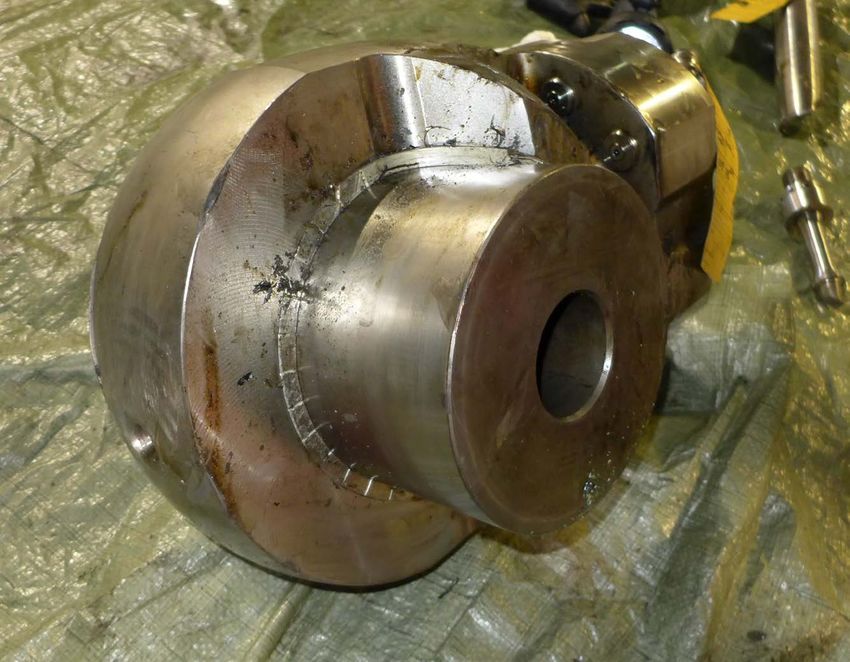
Figure 8:    Escape route vertical ladder and safety chains

Figure 9:    Upper vehicle deck

Figure 10:   CO2 remote release station

Figure 11:   CO2 bottle room

Figure 12:   Fire damage to upper engine room (looking forward)

Figure 13:   MAN 48/60 engine (engine shown 14V48/60B)

Figure 14:   Connecting rod assembly

Figure 15:   B5 small end with piston pin

Figure 16:   Crankcase oil mist detector

Figure 17:   Port side main engine

Figure 18:   Starboard crankcase damage at B5

Figure 19:   Section of A5 connecting rod (after removal from engine room)

Figure 20:   B5 components on starboard side deck plates

Figure 21:   A5 cylinder viewed from engine sump

Figure 22:   B5 liner (looking up to inlet/exhaust valves from engine sump)

Figure 23:   Diesel Service Group workshop and milling machine (inset)

Figure 24:   Diesel Service Group: small end piston pin bearing bush renewal procedure

Figure 25a: A5 small end upper half

Figure 25b: A5 small end fatigue fracture

Figure 25c: A5 looking forward and fatigue fracture

Figure 26:   MAN – Finlandia Seaways’ small ends investigation

Figure 27:   Botnia Seaways small end heat damage (circled)

Figure 28:   Carbon dioxide bottle operating valve

Figure 29:   Distribution of EEBDs in or near to the engine room and escape routes

Figure 30:   Stress/strain curve

Figure 31:   Crack propagation

Figure 32:   Plastic protractor under polarising light showing stress concentration
TABLES

Table 1:   Key alarms relating to the engine failure and engine room fire

Table 2:   MAN’s planned maintenance schedule

Table 3:   A5 small end overhauls and inspections

Table 4:   Finlandia Seaways’ main engine connecting rods, including small end
           damage

Table 5:   Lloyd’s Register Component Survey List

ANNEXES

Annex A    MAN inspection report

Annex B    MAN customer information no. 344/2015

Annex C    The Test House (Cambridge) Ltd metallurgical report

Annex D    Lloyd’s Register Examination of Surveyable Machinery Items by Chief
           Engineers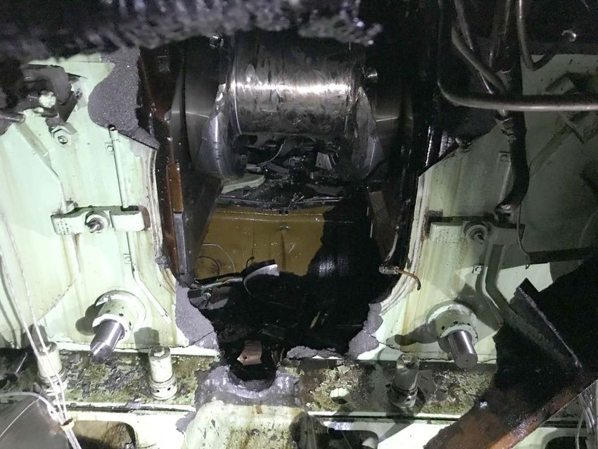
GLOSSARY OF ABBREVIATIONS AND ACRONYMS
APT               -   Annual Performance Test
bar               -   metric unit of pressure: 1bar is equal to 100,000 pascals
BSU               -   Bundesstelle für Seeunfalluntersuchung
CCR               -   Cargo control room
C/E               -   Chief engineer
C/O               -   Chief officer
CO2               -   Carbon dioxide
CPP               -   Controllable pitch propeller
CSM               -   Continuous Survey Machinery
DFDS              -   DFDS Seaways AB-Lithuania
DSG               -   Diesel Service Group UAB
ECR               -   Engine control room
EEBD              -   Emergency escape breathing device
Hz                -   Hertz
IMO               -   International Maritime Organization
kg                -   kilogramme
kW                -   kilowatt
LMSA              -   Lithuanian Maritime Safety Administration
LR                -   Lloyd’s Register
LTSA              -   Lithuanian Transport Safety Administration
MAN               -   MAN Diesel and Turbo SE [renamed MAN Energy SE on 26/6/2018]
                      (engine manufacturer)
MAN PrimeServ     -   Brand name for MAN’s aftersales and maintenance service division
mbar              -   millibar
MCA               -   Maritime and Coastguard Agency
MGN               -   Marine Guidance Note
mm                -   millimetre
nm                -   nautical miles
OMD               -   Oil mist detector
OOW               -   Officer of the watch
Piston pin bush   -   Connecting rod small end piston pin bearing bush
PMS               -   Planned Maintenance System
RINA              -   Registro Italiano Navale
RMRS              -   Russian Maritime Register of Shipping
rpm               -   revolutions per minute
SOLAS             -   International Convention for the Safety of Life at Sea 1974, as
                      amended
TAIID             -   Lithuanian Transport Accident and Incident Investigation Division
TTH               -   The Test House (Cambridge) Ltd
UPS               -   Uninterruptible power supply
UTC               -   Universal Co-ordinated Time
V                 -   volt
VDR               -   Voyage data recorder
VHF               -   Very high frequency
2/E               -   Second engineer
3/E               -   Third engineer

TIMES: all times used in this report are UTC unless otherwise stated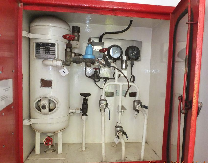
SYNOPSIS
At 2003 on 16 April 2018, the Lithuanian registered ro-ro cargo vessel Finlandia Seaways
suffered a catastrophic main engine failure that caused serious structural damage to the
engine and a fire in the engine room. The vessel’s third engineer, who was on duty in the
engine room at the time, suffered serious smoke-related lung, kidney and eye injuries
during his escape.

Finlandia Seaways was 11nm east of Lowestoft on a regular voyage from Zeebrugge to
Rosyth when one of the main engine’s connecting rods broke. Several of the engine’s major
internal rotating components were thrown through the side of the crankcase into the engine
room, and a short but intense fire occurred. Within 20 minutes the crew had conducted a
muster, sealed the engine room, activated its carbon dioxide fixed fire-fighting system and
extinguished the fire. The third engineer was recovered by coastguard helicopter to Norfolk
and Norwich hospital for medical care, and made a successful recovery.

The MAIB’s technical investigation was carried out with support of the Lithuanian Transport
Accident and Incident Investigation Division and the engine manufacturer, MAN Diesel and
Turbo SE. The investigation identified that a fracture of the connecting rod small end had
led to the sudden failure of the main engine. The investigation also found that the method
used to replace the connecting rod small end piston pin bearing bushes by the vessel
manager’s maintenance support contractor had introduced stress raisers that signficantly
increased the likelihood of crack initiation and fatigue failure.

Other factors that contributed to the engine failure included: standards of maintenance
management; lack of appreciation of the importance of following the engine manufacturer’s
instructions for the removal and refitting of the piston pin bearing bushes; and external
oversight of the engine maintenance process.

With regard to the emergency response, although the carbon dioxide fire-fighting system
was activated successfully, the third engineer was fortunate to have survived given that
there were no emergency escape breathing devices on his escape route. In common
with other accidents in which carbon dioxide has been released following a fire, the
inability to confirm which gas bottles had discharged hampered re-entry to the engine
room. In addition to this, the voyage data recorder did not record the incident due to the
uninterruptible power supply failing.

On 27 July 2018, the MAIB and the Lithuanian Transport Accident and Incident
Investigation Division wrote to MAN Diesel and Turbo SE and the vessel’s classification
society recommending that they provide technical advice to Finlandia Seaways’ operator
to reduce the likelihood of a similar accident occurring in the future. In response, Finlandia
Seaways’ sister vessel was withdrawn from service and its engine connecting rods
removed and replaced. In addition to many actions taken by stakeholders as a result of
this accident, further recommendations aimed at addressing the safety issues raised in
this report have been made to the vessel operators, DFDS Seaways AB-Lithuania and its
engine maintenance support contractor, Diesel Service Group.

                                                                                                 1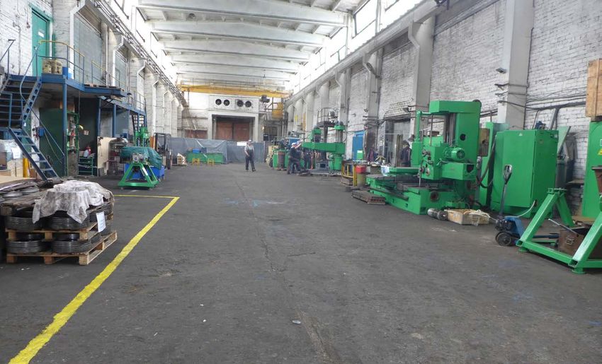
SECTION 1 - FACTUAL INFORMATION
    1.1    PARTICULARS OF FINLANDIA SEAWAYS AND ACCIDENT

    SHIP PARTICULARS
    Vessel’s name                         Finlandia Seaways
    Flag                                  Lithuania
    Classification society                Lloyd’s Register
    IMO number/fishing numbers            9198721
    Type                                  Ro-ro cargo vessel
    Registered owner                      DFDS Seaways AB-Lithuania
    Manager(s)                            DFDS Seaways AB-Lithuania
    Construction                          Steel
    Year of build                         2000
    Length overall                        162.58m
    Gross tonnage                         11530
    Minimum safe manning                  13
    Authorised cargo                      Freight vehicles

    VOYAGE PARTICULARS
    Port of departure                     Zeebrugge
    Port of arrival                       Rosyth
    Type of voyage                        International
    Cargo information                     A mixture of heavy goods vehicles, containers, cars,
                                          campervans and caravans
    Manning                               19
    Passengers                            4

    MARINE CASUALTY INFORMATION
    Date and time                         16 April 2018 at 2003 (2203 ship’s time)
    Type of marine casualty or incident   Serious Marine Casualty
    Location of incident                  11 miles east of Lowestoft
    Place on board                        Engine room
    Injuries/fatalities                   One injury
    Damage/environmental impact           Main engine structural damage; fire damage in
                                          engine room
    Ship operation                        On passage
    Voyage segment                        Mid-water
    External & internal environment       South-westerly wind, slight sea
    Persons on board                      23

2
1.2 NARRATIVE
1.2.1 Passage from Zeebrugge
At 1445 on 16 April 2018, Finlandia Seaways’ (Figure 1) main engine was started
in preparation for leaving port. On duty in the engine room were the chief engineer
(C/E), second engineer (2/E) and an electrician. The vessel’s relief C/E was also in
the engine room. At 1510, engine control was passed to the bridge and, at 1545, the
vessel departed Zeebrugge on passage to Rosyth, Scotland. At 1600, the on watch
2/E was relieved by the third engineer (3/E) and the former left the engine room.
At 1610, the vessel cleared Belgium’s 12nm coastal limit and the engineers began
to change over the engine fuel supply from low sulphur marine diesel oil to heavy
fuel oil. This was completed at 1642 and, by 1800, the C/E, relief C/E and electrician
had all left the engine room. The on watch 3/E monitored machinery operating
parameters from the engine control room (ECR) and undertook hourly inspection
rounds of the engine room.
Image courtesy of www.shipspotting.com
Figure 1: Finlandia Seaways
1.2.2 The engine failure and subsequent fire
At about 2000, the 3/E left the ECR and commenced his hourly rounds of the engine
room and machinery spaces. Shortly after entering the purifier room (Figure 2), he
heard loud metallic knocking sounds coming from the engine room. At the same
time, powerful vibrations were being felt on the bridge by the officer of the watch
(OOW), who immediately checked the propeller pitch angle and main engine speed
gauges. The OOW saw that both gauges were fluctuating and immediately reduced
the propeller pitch from 60% to 25%. He then saw that the fuel consumption meter
was also fluctuating and giving abnormal readings, while various engine warning
lights were illuminated.
3Figure 2: Engine room purifier room
The 3/E opened the purifier room door, looked out into the engine room and saw
smoke rising from the port forward end of the main engine. The noise and vibration
levels rapidly increased and, sensing danger, the 3/E ran back into the purifier room
and crouched behind one of the purifiers. Almost immediately, at 2003, there was a
loud bang and flames flashed past the open purifier room door (Figure 3) and the
space filled with thick black smoke. The ship blacked out1, but within seconds the
emergency generator cut-in and the emergency lighting came on. Despite this, the
smoke in the engine room had reduced the 3/E’s visibility to almost nothing.
1.2.3 Emergency response
The master, who had been alerted by the strong ship vibrations, arrived on the
bridge as the blackout occurred. The fire alarm system had been activated and the
bridge alarm panel indicated that all zones within the engine room were affected.
The master immediately took command and put the vessel’s controllable pitch
propeller (CPP) to zero pitch. He then instructed the OOW to sound the general
alarm and make an intercom broadcast stating that it was a genuine emergency and
that the crew should go to their muster stations. At about the same time, the chief
officer (C/O) arrived on the bridge and reported that he had seen smoke emitting
from the funnel.
1
The sudden and total failure of the ship’s main electrical power supply.
4Heat damage to door
Figure 3: Purifier room door
Like the master, many of the crew members had been alerted by the ship vibrations
and had already begun to react. The C/E had noticed that the main engine’s No.A5
cylinder exhaust gas temperature deviation alarm had activated on his cabin alarm
panel. He initially thought it could be related to a fuel system problem. As he left his
cabin for the engine room, the blackout occurred.
The C/E continued aft to the port side of the main vehicle deck and opened the
engine room access door. He was met by significant smoke and some heat. He
shouted out for the 3/E but heard no reply and was forced back onto the vehicle
deck. He then tried to enter the ECR via the cargo control room (CCR) (Figure 4)
and was again faced with smoke and heat. There was no sign of the 3/E. The C/E
called the bridge from the steering gear space and informed the master of the fire
in the engine room. He then operated the engine room fuel systems’ quick-closing
valves (Figure 5) and fuel pump emergency stops from the control box adjacent to
the ECR.
56
Cargo control room Engine control room
Access from ECR to engine room
Figure 4: Access to ECR, CCR from vehicle deckFigure 5: Control station for the engine room fuel systems’ quick-closing valves
In the purifier room, the 3/E realised that his nearest escape route would take him
past the main engine at cylinder head level and decided to use the secondary
escape route at the aft end of the engine room (Figure 6). He took a deep breath
and then left the purifier room. On entering the dense black smoke, the 3/E ducked
underneath the main engine exhaust gas trunking and ran aft past the two auxiliary
generators. The escape route (Figure 7) led him to the first of three vertical ladders
(Figure 8). When he climbed the first ladder, he struggled to get past the ladder
platform guard rail safety chains and fell back down the ladder three times, losing
his torch in the process, before making good his escape.
The vessel’s four passengers were taken to their assembly point on the upper
vehicle deck and an initial crew muster was attempted at the port lifeboat. Some
of the crew involved in the fire-fighting effort reported in via hand-held radios.
The engine room fire party, which had arrived on the upper vehicle deck and was
running out fire hoses, reported the 3/E missing. A second muster took place on
the upper vehicle deck, where the 2/E and motorman had already begun to shut the
engine room fire flaps.
At 2013, the 3/E escaped from the engine room through the funnel casing
weathertight door onto the upper vehicle deck (Figure 9). He then collapsed onto
the deck, gasping for breath and struggling to see. The 2/E saw the 3/E collapse
and went to help him. The 2/E radioed the bridge and informed the master that the
3/E required medical assistance. At 2015, on instruction from the master, the OOW
contacted Humber Coastguard and requested a helicopter.
78
Primary escape route
3/E emergency escape route Secondary escape route
Main engine
Aft Fwd
Auxiliary generators Mezzanine deck
Figure 6: Purifier room and engine room tween deck (shaded blue) with 3/E’s escape routeUpper vehicle deck
AFT FWD
Mezzanine deck
Figure 7: Elevation showing the primary escape route from the purifier room to the main vehicle deck and the secondary escape route taken by the
third engineer
(Green: primary escape route | Blue: secondary escape route)
9Guard rails
Safety chain
Platform
Ladder
Figure 8: Escape route vertical ladder and safety chains
Funnel casing weathertight door
Figure 9: Upper vehicle deck
10With confirmation that the 3/E had been found, all crew and passengers accounted
for, the fire flaps closed and the engine room fuel supply isolated, the C/E advised
the master to release the engine room’s carbon dioxide (CO2) fixed fire-extinguishing
system. The master then called the 2/E and ordered him to operate the CO2 system
for the engine room.
The 2/E and the second officer went to the CO2 remote release station (Figure 10)
on the forecastle deck and, at about 2020, released the CO2 into the engine room.
The 2/E then went down to the main deck and entered the CO2 bottle room (Figure
11). He found that the control lever for the engine room had operated correctly and
that the CO2 pipework had frosted. He also noted that the main CO2 supply line
pressure gauge was indicating about 20bar pressure, and a short time later he saw
it reduce to zero.
Figure 10: CO2 remote release station Figure 11: CO2 bottle room
At 2027, Humber Coastguard tasked rescue helicopter R912 based at Humberside
to evacuate the injured 3/E. Two warships were also in the vicinity and were tasked
to close on Finlandia Seaways and stand-by if required.
While the medical team continued to provide medical support to the 3/E, other
crew members were tasked to monitor engine room boundary temperatures. This
was initially carried out by using their hands and, latterly, with fridge thermometers.
Temperatures were measured and logged regularly and appeared to reduce over
time.
The master instructed the bosun to drop the port anchor; one shackle ran out before
it jammed. The starboard anchor was then released and it, too, initially jammed.
However, with assistance from the bosun it ran out and held the ship with four
shackles.
11At 2203, after diverting to refuel, R912 arrived at Finlandia Seaways. At 2247, the
3/E was recovered into the helicopter and taken to Norfolk & Norwich hospital,
where he received medical care for smoke-related lung, kidney and eye injuries. At
2337, Finlandia Seaways’ master advised Humber Coastguard that the fire situation
had been stabilised.
Finlandia Seaways was initially towed to the Hawke anchorage on the River Humber.
A further tow was arranged, with the vessel arriving in Immingham on 20 April 2018,
where it was boarded by the Humberside Fire & Rescue Service to confirm that the
engine room fire had been extinguished.
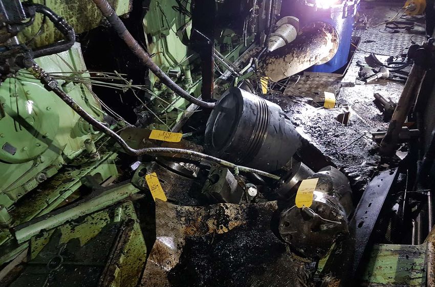
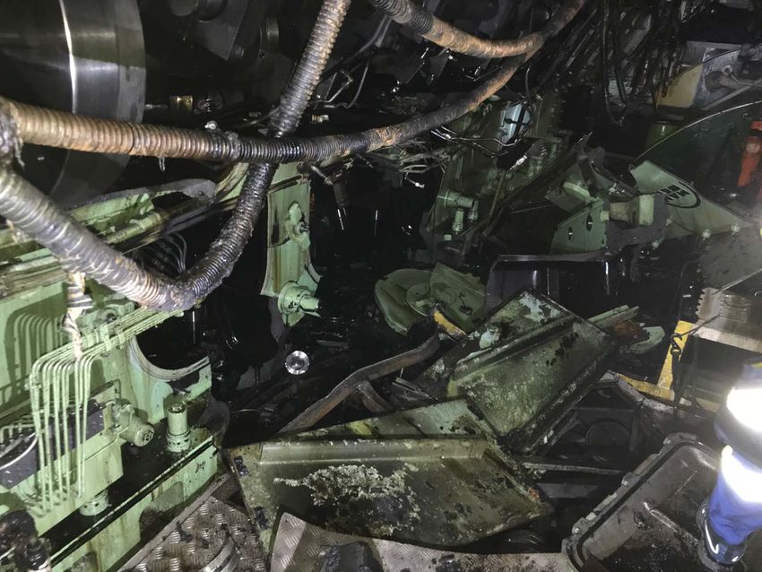
1.2.4 Engine room fire damage
Fire damage was sustained primarily at the tween deck level in the engine room,
with severe heat damage to the upper part of the main engine and engine room
deckhead (Figure 12). Most of the heat damage was sustained around the main
engine cylinder heads, and to auxiliary equipment on the periphery at the forward
end of the engine room. Further aft, towards the two auxiliary generators, smoke
damage was the major contributor.
On the bottom plates, the main area of heat damage was at the port forward engine
room access door and the adjoining stairwell. Impact damage to the access door
caused by the components ejected from the main engine had enabled heat and
smoke to enter the stairwell, which had then funnelled up the next two decks to the
ECR.
Deck head
Port side mezzanine walkway
Main engine
Cylinder head A1
Figure 12: Fire damage to upper engine room (looking forward)
1.3 CREW
Finlandia Seaways was crewed by 19 Lithuanian nationals, one of whom had just
joined the vessel in Zeebrugge as the relief C/E. Crew members normally worked 4
weeks on, 4 weeks off; or 6 weeks on, 6 weeks off.
12Although Finlandia Seaways had an unattended machinery space2 notation, the
vessel’s engine room was normally manned at all times with the 2/E and 3/E
undertaking 4 and 6-hour watches in rotation3. The C/E, electrical engineer and
motorman were day workers and typically worked from 0800 to 1800.
1.4 ENVIRONMENTAL CONDITIONS
At the time of the accident the wind was southerly, force 4-5, the sea was slight with
fair weather and the visibility was good.
1.5 FINLANDIA SEAWAYS
Finlandia Seaways was a Lithuanian registered roll-on roll-off cargo vessel. It was
owned by DFDS Seaways AB-Lithuania (DFDS) and operated by DFDS A/S. It was
built in 2000 and purchased, along with its sister vessel Botnia Seaways, by DFDS
in 2009. When first acquired, Finlandia Seaways and Botnia Seaways were named
Tor Finlandia and Tor Botnia. The vessels were renamed in 2012.
Finlandia Seaways had provided a regular service on the Zeebrugge to Rosyth route
since 2009. It had been classed by Lloyd’s Register (LR) since new and, at the time
of the accident, its certificate of class was valid until 9 August 2020.
DFDS A/S is a Danish shipping and logistics company. At the time of the accident it
operated 28 vessels on passenger and freight services on 24 routes across northern
Europe and within the Mediterranean Sea. DFDS Lithuania’s management and
technical teams were based in Klaipeda, Lithuania.
1.6 MAIN ENGINE
1.6.1 Overview
The vessel’s main engine was a 12,600kW MAN Diesel and Turbo SE (MAN) 12V
48/60 single-acting medium speed four-stroke diesel engine (Figure 13). It had
two banks of six cylinders arranged in a “V” configuration with two turbochargers,
one per bank. The ‘48/60’ referred to the bore of the cylinders and the stroke of the
pistons in centimetres.
The engine operated at a fixed speed of 500rpm, with load changes controlled by
fuel input. It was connected via a flexible coupling to a single reduction gearbox,
which drove a single CPP at an operating speed of 155rpm. The engine also drove
a 400V, 1,500kW, 50Hz electrical alternator. At the time of the accident, the engine
had a total of 110,662 running hours.
The MAN 12V 48/60 engine was commonly used in both ship propulsion and
shoreside power generation systems.
2
Unattended machinery spaces are required to have levels of automation that allow them to be periodically
unattended. Typically, outside normal daily working hours. If there is a malfunction in any machinery, or
any operating parameters are exceeded, an alarm will be sounded in the duty engineer’s cabin and other
communal accommodation areas. It is then the duty engineer’s responsibility to investigate.
3
Engine room watch routine – 2/E: 0000-0400 and 1200-1800; 3/E: 0400-0800 and 1800-0000.
13Cylinder heads
A1 Cylinder block
Camshaft casing
Crankcase doors Crankcase Oil tray
Figure 13: MAN 48/60 engine (engine shown 14V48/60B)
1.6.2 Engine design and key components
The engine design comprised a single-piece cast iron crankcase. The cylinder liners
were separated from each other and were mounted in the engine frame, and the
crankshaft was underslung. The crankcase was fitted with crankcase explosion relief
valve doors, two per crank throw, i.e. one on each side. The crankcase relief valve
operating pressure was 50mbar.
The forged crankshaft had two counterweights per crankpin journal to compensate
for the oscillating masses. The counterweights were held in place by anti-fatigue
bolts. All the major bolting arrangements within the crankcase were hydraulically
tensioned.
The cylinders were numbered 1 to 6 from aft to forward and labelled “A” for the port
side bank and “B” for the starboard side bank. Each cylinder bank had a camshaft,
which operated four valves per cylinder head and the fuel injection pumps. A
cylinder and its associated valves, piston and con rod was referred to as a ‘unit’, i.e
unit A1, unit B1 etc.
The piston connecting rods were cast in one piece. During manufacture, the
connecting rod shank was cut below the small end eye, flanged and bolted together.
This was to facilitate piston removal without the need to remove the connecting
rod big end bearing. The shank’s flanged connection was the weakest part of the
connecting rod assembly (Figure 14).
The connecting rod small ends were stamped with the manufacturer’s unique
identification code numbers (e.g. COC 1234) and LR identification numbers for
survey purposes. A one-piece piston pin bearing bush (piston pin bush4) was
4
Connecting rod piston pin bearing bushes are also often referred to as small end bushes.
14installed into the eye of the small end (Figure 15). The surface finish of the inner
face of the small end eye was prepared during manufacture by shot-peening5 to
reduce the potential for fatigue fractures developing under high operational loads.
The masses of key rotating and oscillating components within the engine were:
piston – 337kg; piston pin – 102kg; connecting rod – 655kg; and crankshaft
counterweight – 525kg.
Upper part of shank with gudgeon pin boss
Small end
Piston pin bearing bush
Flanges
Split shank with necked-down bolts
Split shank
Connecting rod bolts
Lower part of shank
Big end
Big end bearing shell
Big end bearing cap
Figure 14: Connecting rod assembly
5
Shot peening is a surface cold worked process of bombarding the material with small high velocity spherical
metal particles (shot), which introduces residual compressive stress.
15Piston pin
Bearing bush
Figure 15: B5 small end with piston pin
1.6.3 Engine condition monitoring and protection systems
The engine was equipped with the following crankcase monitoring systems:
● main bearing temperature monitoring system,
● splash oil monitoring system, and
● oil mist detector (OMD).
The crankshaft bearing temperature monitoring system used temperature sensors
that were fitted in the underslung crankshaft main bearings. The sensors transmitted
electronic signals to the engine safety system. The splash oil monitoring system
measured and compared the oil temperature dripping from the connecting rod
bearings. Both temperature monitoring systems could trigger an alarm and
automatically shut down the engine.
The OMD was manufactured by Schaller Automation and was fitted on the starboard
side of the engine crankcase (Figure 16). The OMD measured and compared the
oil vapour concentrations present in each crankcase compartment and provided
an audible and visual alarm when anomalies were identified. The OMD could
also trigger an engine shutdown if high levels of mist developed in one or more
compartments.
16Figure 16: Crankcase oil mist detector
High oil mist concentrations are created in a crankcase by the presence of hot spots,
which cause oil to evaporate and then form a mist when they start to condense. The
ignition of the oil mist can lead to violent crankcase explosions, the consequence
of which can be severe, including death and serious injury to crew, and extensive
engine damage.
1.6.4 Post-fire inspection
Finlandia Seaways’ main engine suffered substantial structural and component
damage during its failure. The engine crankcase structure was ruptured on the port
and starboard sides of units five and six, with crankcase explosion relief valve doors
and large sections of the crankcase casting being propelled several metres across
the floorplates (Figures 17 and 18).
A5’s connecting rod (Figure 19), the lower half of its piston and its crankshaft
counterweight had been ejected through the starboard side of the crankcase. The
connecting rod had separated at its small end eye, shank flange and big end bolted
connections. The big end bearing cap was found at the forward end of the engine
room deck plates on the port side. B5’s connecting rod and its piston had also been
ejected from the crankcase and were found on the starboard deck plates (Figure
20), the connecting rod assembly having separated at its bolted shank flange. The
broken upper half of A5’s small end, and B5’s big end lower half, were found in the
engine room starboard bilge.
17Broken crankcase units 5 and 6
Crankcase door
Figure 17: Port side main engine
Crankshaft big end bearing pin A5 and B5
Debris in sump
Broken crankcase
Figure 18: Starboard crankcase damage at B5
18Figure 19: Section of A5 connecting rod (after removal from engine room)
B5 piston
B5 conrod small end
Figure 20: B5 components on starboard side deck plates
The upper part of A5’s piston and its piston pin6 remained in the upper section of
the cylinder liner (Figure 21); the lower section of the cylinder liner had shattered
and dropped into the sump. Although badly damaged at its lower end, B5 cylinder
liner did not suffer the same level of damage as A5 (Figure 22). Impact damage
had occurred to the crankshaft at number five crankpin journal and the crankpin
webs. The camshaft covers for both banks had become detached and the A-bank
camshaft had also been partially displaced.
6
Piston pins are also widely referred to as gudgeon pins.
19Piston
Piston pin
Upper section of liner
Figure 21: A5 cylinder viewed from engine sump
Broken liner
Cylinder head and valves
Figure 22: B5 liner (looking up to inlet/exhaust valves from engine sump)
201.6.5 Engine room alarms
During the engine failure and ship blackout many alarms activated in the engine
control room and on the bridge. A summary of key alarms is listed in Table 1 below.
Ship’s time
Alarm Alarm State
(UTC+2)
2203:21 Main engine crankcase oil mist High
2203:22 Main bearing 6 high temperature Sensor (Fault)
2203:22 Main engine splash oil monitor Fail
2203:24 Lube oil pump stand-by Start
2203:25 Main engine slowdown
2203:28 Main bearing 5 high temperature Sensor (Fault)
2203:28 Main bearing 7 high temperature Sensor (Fault)
2203:32 Main bearing 1 high temperature Sensor (Fault)
2203:32 Main bearing 2 high temperature Sensor (Fault)
2203:32 Main bearing 3 high temperature Sensor (Fault)
2203:32 Main bearing 4 high temperature Sensor (Fault)
2203:35 Fire alarm
2203:43 Cylinder A5 exhaust gas out temp Low
Table 1: Key alarms relating to the engine failure and engine room fire
1.6.6 Planned maintenance
The main engine planned maintenance work on board Finlandia Seaways was
conducted in accordance with the schedules contained in the vessel’s electronic
planned maintenance system (PMS). The PMS schedules were based on MAN’s
engine running hours maintenance schedule (Table 2).
Description Hours
Check one big end bearing 6,000
Remove, clean/check one piston 6,000
Check all pistons 12,000
Remove one piston pin 12,000
Disassemble one piston 12,000
Replace all big bearing shells and small end bearing bushes 36,000
Table 2: MAN’s planned maintenance schedule
21Day to day defect maintenance and minor planned maintenance work on the main
engine were carried out by the vessel’s engineers. This included the replacement
of fuel injectors and fuel pump servicing. In addition, the engineers conducted
routine inspections of the engine’s crankcase, camshafts, bearings, liners, bolt
security and lubricating oil supply lines. They also took regular fuel and lubricating
oil samples and sent them ashore for analysis. Major maintenance work, such as
piston removal, inspection and overhaul was usually carried out by shore contractors
during maintenance layover periods at Rosyth. The attendance of the shore
contractors was facilitated by the vessel’s technical superintendents.
The maintenance requirements for the main engine connecting rods and pistons
were set out in the same PMS schedules, under the headings No.1 Unit A; No.1
Unit B, etc. To assist with piston overhauls and enable swifter maintenance period
turnarounds for Finlandia Seaways and Botnia Seaways, DFDS held six spare small
ends. To help monitor small end running hours, the vessels’ C/Es recorded their
running hours, based on their COC number, on a separate spreadsheet.
1.6.7 Outsourcing of main engine work
Since taking operational control of Finlandia Seaways and Botnia Seaways in
2009, DFDS had outsourced most of the vessels’ main engine repair work to the
ship repair company Diesel Service Group UAB (DSG). Initially, DSG was tasked
to work alongside MAN service engineers but, over time it was contracted to carry
out increasing amounts of the routine main engine work alone. MAN was used only
to do complex tasks that required specialist tools and specific expertise. Recent
work items undertaken on board Finlandia Seaways by MAN included replacing a
camshaft in 2016, replacing the Vulcan shaft coupling and overhauling the engines’
oil and freshwater pumps.
DFDS had held discussions with DSG to ascertain its capability to undertake
specific tasks. In this respect, DFDS considered that DSG had the necessary tools
and skills to undertake replacement of the connecting rods’ piston pin bushes. No
written agreement for this was recorded.
The last visit by DSG (concurrent with an engine inspection by ship’s engineers)
had taken place on 3 April 2018, with engine running hours at 110,365. During the
visit, DSG replaced the engine thrust bearing and carried out crankshaft deflection
measurements.
1.7 DIESEL SERVICE GROUP UAB
1.7.1 Overview
DSG was established in 1995 and was based in Klaipeda, Lithuania. It specialised in
the repair of marine diesel engines and other engine room and deck equipment. The
company had provided a service for a wide range of ships. Many of its technical staff
had previously worked in the Western Ship repair yard, Klaipeda.
1.7.2 Certification
DSG was certified by the Lithuanian Maritime Safety Administration (LMSA)7 to
perform repairs, checks and testing of ships’ main and auxiliary mechanisms,
devices and related systems. DSG’s certification was renewed on 22 January 2016,
and it was audited by LMSA on 28 February 2017; no non-conformities were raised.
7
The LMSA was renamed the Lithuanian Transport Safety Administration (LTSA) on 1 December 2017.
22DSG was also registered with the Russian Maritime Register of Shipping (RMRS),
which had issued a ‘Certificate of Firm Conformity’ in November 2015. The
certificate was valid for 5 years subject to annual confirmation and stated that DSG
was certified for, among other things:
Code 22014000 ‘Construction, conversion, modernization and repair of items of
technical supervision products’, include:
1. Repair of ship’s engines up to 8500kW. [sic]
DSG was also accredited by the Italian classification society Registro Italiano Navale
(RINA) with a ‘Workshop Approval Statement’, covering the design, diagnostics,
maintenance and repair of ships’ systems and equipment. The certificate was
valid until 18 March 2019. The approved workshop status was based on evidence
provided, including qualification levels and experience, and a review of the workshop
procedures and instructions. The statement did not specify any engine size or power
limitation.
DSG was not required to have a quality management system but was in the process
of applying for ISO 9001:20008 and gaining third party certification. In this respect,
a quality management system was under development, including a quality policy,
project planning, division of responsibilities and quality objectives. To perform the
maintenance on various engines, it had a range of marine engine manufacturers’
instructions, including MAN and S.E.M.T. Pielstick engines. DSG was not an
accredited service provider for MAN.
1.8 CONNECTING ROD PISTON PIN BUSH RENEWAL
1.8.1 MAN guidance and procedure
The wear limit between the piston pin and its bearing bush was 0.46mm. From
experience, MAN expected the bearing pin bush to be replaced after 36,000 running
hours.
MAN’s piston pin bush removal procedure required the use of a milling machine to
accurately cut a groove along the internal face of the bush. The cut needed to be
a sufficient depth to leave less than 0.5mm of material on its outer edge without
cutting into the surface of the connecting rod small end. The compression force
acting on the bush due to its interference fit9 in the eye of the small end, caused the
remaining thin layer of material to collapse inward, allowing the bush to be removed.
New bushes were required to be cooled and shrunk using liquid nitrogen before they
could be inserted in the small ends. The MAN 48/60 engine maintenance manual
stated:
Important! If required, the piston pin bush should be replaced in a Service
Workshop, as the bush is to be cooled down before being installed.
8
ISO 9001:2000 specifies requirements for a quality management system where an organisation needs to
demonstrate its ability to consistently provide a product that meets the customer and applicable regulatory
requirements.
9
An interference fit (press fit and shrink fit) is a frictional connection for rotating components. Joint pressure in
the friction surface between the two components is necessary for the torque to be effectively transmitted; this
pressure is generated by the deformation of the two components, e.g. a shaft and its bearing.
23MAN PrimeServ, the brand name for MAN’s service division, offered aftersales and
through-life maintenance support for all MAN engines and systems. It provided a
worldwide, round-the-clock service and had a global network of service workshops
and test facilities. It also offered a variety of training courses for its customers’
marine engineers and other technical staff. MAN PrimeServ had two service
stations worldwide that it considered equipped and able to conduct the bush renewal
process; one of them was based at MAN’s headquarters in Hamburg, Germany.
1.8.2 Diesel Service Group guidance and procedure
DSG carried out work on a range of vessels and engine types, including five
operated by DFDS. On average, DSG had replaced two to three piston pin bushes
per year for DFDS, of which about 24 were fitted to the MAN 12V 48/60 engines on
board Finlandia Seaways and Botnia Seaways.
The removal and installation of the MAN connecting rod piston pin bushes was
carried out by DSG at its workshops in Klaipeda (Figure 23). DSG’s documented
piston pin bush removing and installing procedure for the MAN 12V 48/60 engine
(Figure 24) was similar to that followed by MAN. To remove the piston pin bush in
accordance with the procedure, one side of the bush had to be bored away using
a milling machine before pressing it out. The new bush needed to be cooled using
liquid nitrogen to – 195ºC and measured before being inserted into the small end
eye; a specialist tool was required to be used when aligning the bush.
DSG employed one person to oversee the work and produce the technical repair
document, and only one technician was permitted to use the milling machine. DSG
was unable to confirm whether anyone else, including possible subcontractors, had
undertaken this work.
Figure 23: Diesel Service Group workshop and milling machine (inset)
24UAB“DieseI Service Group"
Nr. S0115-
Piston pin bush removing and installing PTECH/DSG
PROCEDURE
M.E. MAN B&W 12V 48/60
The piston pin bush should be replaced in a service workshop, because it needs to be supercooled for assembly.
1.Piston pin bush removing. Piston pin bush to be removed by machining of one side with boring machine. Bush to be pressed
out.
2. Piston pin bush installing. The new bush shall be liquid nitrogen refitted (-195 C temperature). The bush shrinking to
be measured prior to installation to provide the easy pass into small end hole.
For the levelling and matching of center hole special tool should be used, as shown in a picture below:
Projection of bush has to be equal from both connecting rod small end sides.
After bush is mounted special tool to be taken out.
The inner bush diameter to be measured when the small end temperature becomes the same as the ambient
temperature.
Engineer technologist
2015.01.15
Figure 24: Diesel Service Group: small end piston pin bearing bush renewal procedure
25DSG carried out similar piston pin bush replacements on S.E.M.T Pielstick engines.
The S.E.M.T Pielstick manufacturer’s instructions specified that the connecting rod
small end bearing bush could be removed by making two diametrically opposed saw
cuts in the bush.
In February 2017, DSG carried out a 12,000-hour overhaul of Finlandia Seaways
unit A5. The total engine running hours was 103,007 and the remarks recorded in
the vessel’s PMS included:
● Piston with connecting rod small end:
○ Dismantling, disassembling, cleaning, measurements, disassembling of
piston, replacement of piston head (used), assembly of piston with new
studs,
○ Replacement of conrod small end, assembling of piston and conrod small
end with new small end bush, installing with new piston rings in accordance
with engine manual.
○ Installing with new piston rings.
The work was carried out in Rosyth, and the small end was replaced with one of
DFDS’s spare small ends (COC 61584), which had been overhauled in November
2016. A summary of A5 small end overhauls based on engine running hours only is
set out in Table 3.
Date Engine operating hours Remarks
20/12/2002 15,885 Piston pin checked ok
03/03/2005 30,631 Pin and bush inspected
25/06/2007 46,279 Piston pin checked
Piston pin bush checked, measured
02/02/2010 60,009
the clearance
Fitted connecting rod with new piston
03/10/2012 75,058
pin bush
07/10/2014 87,637 Piston pin bush replaced
Replacement of con rod small end with
21/02/2017 103,007
new small end bush [COC 61584]
Table 3: A5 small end overhauls and inspections
The MAIB and Lithuanian Transport Accident and Incident Investigation Division
(TAIID) inspectors visited DSG on 16 July 2018. DSG was unable to identify when,
or by whom, the A5 piston pin bush had been replaced.
A subsequent inspection by LTSA on 4 September found that DSG was unable to
provide evidence to confirm that liquid nitrogen had been used to shrink the piston
pin bush during the overhaul of the small ends.
As DSG was not accredited by MAN, it did not have access to MAN’s piston pin
bush removal and installation tools and procedures.
261.9 ENGINE MANUFACTURER’S POST-FAILURE ENGINE INSPECTION
AND GUIDANCE
1.9.1 Engine inspection and failure mode analysis
MAN attended Finlandia Seaways after the accident while it was berthed alongside
in Immingham. The engine debris had been left untouched to allow their site
examination. Independently, but like the MAIB’s initial examination, the focus of
interest became the A5 connecting rod. The upper half of the broken small end
was found in the debris field on the starboard side of the engine, and the severely
damaged piston pin bush was found nearby. Inspection of the failed surfaces of
the small end identified a potential fracture face on one side of the small end eye
(Figures 25a, 25b and 25c).
The remnants of the failed A5 small end, the B5 small end and various other
components, including the OMD, were taken ashore by MAN for further analysis.
MAN examined the failed A5 connecting rod small end on 22 June 2018 at its
laboratory in Augsburg, Germany. MAIB inspectors and a DFDS representative were
in attendance during the examination process. Work carried out included:
● microscopic examination of the small end fracture faces,
● metallurgical composition testing, and
● notch toughness testing10.
The MAN investigation of A5 connecting rod small end (COC 61584), identified that:
● The small end was originally fitted to Botnia Seaways at build in 1999 and
was the latest design version.
● It had never been serviced by MAN.
● The fracture might have occurred over a period of weeks or months.
● Due to the damage on the fracture surface, it was not possible to identify the
locus of the fracture.
● The chemical composition did not fully correspond with the material
specification. The ductile properties of the material were slightly below the
required specification.
● A microsection showed a quenched and tempered microstructure but with an
aggregation of non-metallic inclusions.
The examination of B5 (COC 113544) found no abnormalities and MAN’s
investigation established that it was delivered in 2007.
In addition, the investigation report (Annex A) concluded that:
● The OMD alarm was the first indicator of a problem, quickly followed by
physical destruction of internal engine components.
10
A standardized high strain-rate test, which determines the amount of energy absorbed by a material during
fracture.
27● The OMD did not have the ability to record alarms or faults to assist the
investigation.
● The A5 small end was probably the first major component to exit the
crankcase.
For engines of the type 48/60, MAN also identified that over half of its engines in
service had accumulated over 100,000 running hours, with two operating at 180,000
running hours without similar small end failures.
Fracture surface
Figure 25a: A5 small end upper half
Base images courtesy of MAN Energy Solutions
Bearing bush A5
Fatigue facture
Crack initial side
Figure 25b: A5 small end fatigue fracture
28Base image courtesy of MAN Energy Solutions
Fatigue fracture
A5
Connecting rod
Figure 25c: A5 looking forward and fatigue fracture
29At MAN’s request, the remaining 10 connecting rod small ends from Finlandia
Seaways were sent to MAN for inspection. After the piston pin bushes were
removed, seven were found to have cuts, or notches, at the edges and on the
internal faces of the small end eyes (Figure 26 and Table 4). The cuts were
symptomatic of the use of a disc cutter or angle grinder.
Small ends: A3; B1; B2 and B4 were subsequently identified as having the same
respective overhaul and installation dates. It is probable that the overhauls were
carried out at the DSG workshop in Klaipeda before installation while the vessel was
alongside in Rosyth.
Small end running
Date overhauled
Cuts or notches
hours at time of
Engine running
New piston pin
engine failure11
found in small
Date installed
installation
bush fitted
Small end
(COC No)
in engine
hours at
end eye
by DSG
A1
29/12/2016 unknown Yes Yes 102,091 88,765
(62085)
A2
06/06/2017 unknown Yes Yes 105,058 89,233
(61868)
A3
15/08/2017 15/08/2017 No Yes 106,399 91,344
(62009)
A4
06/06/2017 unknown Yes Yes 105,058 88,946
(62110)
A5 21/02/2017 11/2016 Yes Unknown 103,007 90,467
(61584)
A6
18/04/2017 unknown Yes No 104,096 88,677
(113538)
B1
02/01/2017 02/01/2017 No Yes 102,140 89,455
(61993)
B2
18/04/2017 18/04/2017 No No 104,096 88,466
(61944)
B3
07/11/2016 07/11/2016 No No 101,146 91,237
(61948)
B4
21/12/2016 21/12/2016 No Yes 102,091 90,389
(61857)
B5
29/12/2016 unknown Yes No 102,091 87,455
(113544)
B6
21/02/2017 unknown Yes Yes 103,007 89,048
(61996)
Table 4: Finlandia Seaways’ main engine connecting rods, including small end damage
11
Engine running hours: 110,662
30Small end investigation
DFDS Finlandia 1135079, 12V48/60
Connecting rod Small ends COC : 62110, 62085,62009, 61857, 61996, 61993, 61868,61584 (A5),
61948, 61944, 113544,113538
Connecting rod small ends Coc starting with 6---- we expect a part running hour higher than 100.000h
1.9.2 Botnia Seaways
Coc: 62110 Coc: 61993 Coc: 61868 Coc: 61857 Coc: 62085
Coc: 62009 Coc: 61996 7 of 11 investigated small ends show
notches!
Non of the small ends shows hints of fretting
in the surface.
Non of the small ends shows hints of cracks
in the surface (MPI)
Ultra sonic investigation underneath notch is
in process (finalisation until 27.07.2018)
Measurement of the bearing bore is in
MAN engines overhauled by DSG. In the letters, the engine manufacturer and
process (finalisation until 27.07.2018)
and TAIID wrote jointly to MAN and LR raising concerns about the risk of similar
MAN Diesel & Turbo EEDFSF R&D Projekt 07.05.2018 < 1 >
catastrophic engine failures on board Botnia Seaways and other vessels operating
Following the initial damage assessments and MAN findings, on 27 July 2018 MAIB
Figure 26: MAN – Finlandia Seaways’ small ends investigation
31classification society were recommended to provide technical advice on actions to
be taken by vessel operators at risk. DFDS subsequently withdrew Botnia Seaways
from service.
Between 6 and 25 August 2018, while out of service in Marseille, France, all of
Botnia Seaways’ main engine connecting rods were replaced. During the initial
inspection of the small ends, the attending LR surveyor identified heat marks on
the inner edge of one of the small ends (Figure 27). MAN specialists examined the
marks and concluded that they were not caused during engine operation. MAN’s
assessment was that the localised heat marks had been caused by the application
of intensive heat from something like a gas welding torch. MAN suggested that
Figure 27: Botnia Seaways small end heat damage (circled)
32this had been to assist with the piston pin bush removal/installation process. MAN
further concluded that the intense local heating would have produced an annealing12
effect of the metal, resulting in structural changes affecting the material strength.
MAN’s subsequent investigation of the 12 small ends returned for inspection
identified:
● Notches/cuts on three small ends.
● Localised heat marks on three small ends.
● Damaged shank bolts on three connecting rods.
● Various levels of other spurious damage and wear.
1.9.3 Engine design modifications and updates
MAN regularly provided targeted customer service information to advise customers
on maintenance updates for specific engine types. Since February 2000, MAN had
distributed 94 customer information documents for the 48/60 engine, including all
the variants.
In 2015, MAN circulated customer information notice No.344/2015 (PCI 344/2015)
(Annex B), which advised that the connecting rod be renewed after 100,000 running
hours. This was primarily based on increased ovality identified in the big end bearing
housings. On receipt of the notice, DFDS checked the ovality of a selection of its
connecting rod big ends during routine maintenance and, finding no ovality, kept
them in service.
Although DFDS had received them, the MAN customer information notices issued
after Finlandia Seaways’ build were not available on board.
1.10 METALLURGICAL ANALYSIS
As the initiation point of the A5 small end fracture was not identified during the
examinations conducted by MAN, the MAIB commissioned The Test House
(Cambridge) Ltd (TTH) to undertake further metallurgical analysis work. The remains
of Finlandia Seaways’ A5 small end, and B5 and B6 small ends were delivered to
TTH in October 2018.
TTH’s initial inspection of A5 identified that:
The fracture surface showed a flat/featureless surface, clear evidence of beach
marks, post fracture mechanical damage on the fracture surface and bearing
contact surface and a secondary crack in the oilway groove perpendicular to the
fatigue fracture.
The conclusions contained in TTH’s report (Annex C) included:
The engine had failed in a catastrophic manner as a result of the A5 connecting
rod small end failing due to fatigue. The fracture had initiated at the bearing
contact surface and propagated through the body.
12
Annealing is a heat treatment that alters the physical and sometimes chemical properties of a material to
increase its ductility and reduce its hardness, making it more workable.
33Due to post fracture mechanical damage it was difficult to identify the point of
initiation.
The intact A6 small end had gouge marks on the edges of the bearing bush contact
surface. The TTH report stated that:
Although the intact small end [A6] showed no evidence of consequential features
due to the gouge marks, such practises should be avoided at all costs as they
can conclude to points of stress raisers.
1.11 EXTERNAL OVERSIGHT
Classification societies conduct periodic reviews of critical machinery components
to ensure they are in an appropriate condition; normally 20% of Class items are
inspected per year over the mandated 5-year survey cycle.
In accordance with LR rules and regulations, Finlandia Seaways was operated on a
Continuous Survey Machinery (CSM) cycle. Consequently, its C/Es were authorised
to carry out examinations of selected machinery while the ship was at sea or in port
when LR was not represented. The process was explained by LR in its document
Examination of Surveyable Machinery Items by Chief Engineers, effective 1 March
2015 (Annex D).
The C/Es’ records of examination were audited annually by an LR surveyor and
confirmatory surveys carried out. LR provided a template statement (Annex D) for
completion by the C/E with a requirement that a copy be provided to the surveyor
and a second copy remain on board.
Applicable machinery items that could be examined by a C/E included:
● main engine connecting rods,
● piston pins, and
● piston pin bushes.
The connecting rod was a certified item and had an LR stamp on it, but its piston pin
bush was considered a consumable item. The replacement of a small end piston pin
bush was considered routine maintenance on the part of the ship owner, and LR did
not expect to be called in by an owner to witness routine maintenance between its
mandated surveys. LR did expect to be notified if a certified component, such as the
connecting rod, had been deemed beyond economical repair and was replaced, had
a defect that was repaired, or if the component was modified.
Cylinder A5 had previously been overhauled on 7 October 2014; the C/E’s statement
of examination was dated 29 December 2014. The examination was then credited
under the CSM cycle by an LR surveyor on 31 January 2015 (Table 5).
34You can also read