Deliverable D6.2 Development of Showcases and Demonstrators - Broadcast and Multicast Communication Enablers for the Fifth-Generation of Wireless ...
←
→
Page content transcription
If your browser does not render page correctly, please read the page content below
Broadcast and Multicast Communication Enablers for the
        Fifth-Generation of Wireless Systems

         Deliverable D6.2
  Development of Showcases and
         Demonstrators

        Version v1.0               Date: 2019/02/28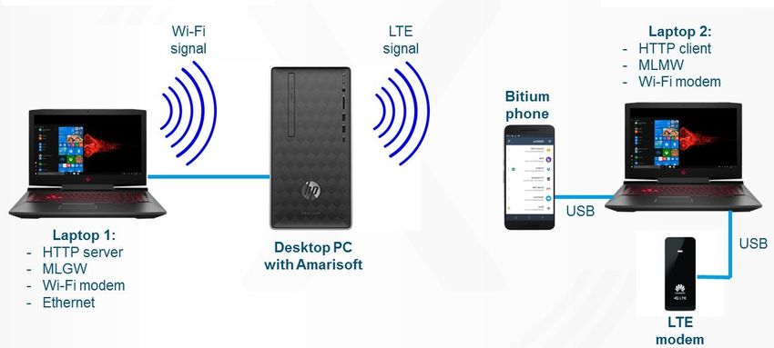
Document properties:
    Grant Number:                                 761498
    Document Number:                              D6.2
    Document Title:                               Development of Showcases and Demonstrators
    Editor(s):                                    Joe Eyles (BBC), Andrew Murphy (BBC), David Vargas
                                                  (BBC), Jordi J. Gimenez (IRT)
    Authors:                                      Joe Eyles, Andrew Murphy (BBC); Tim Stevens, Rory
                                                  Turnbull (BT); Duy Kha Chau, Alain-Pierre Brunel
                                                  (Broadpeak); Roman Odarchenko (Bundeslab); Tuan
                                                  Tran (Expway); Heikki Kokkinen (Fairspectrum); Jordi J.
                                                  Gimenez, Swen Petersen, Fabian Sattler, Benedikt Vogel
                                                  (IRT); Menno Bot (one2many); Tero Jokela (TUAS); De
                                                  Mi (UniS); Ece Öztürk (NOMOR); Ioannis Selinis (UniS);
    Contractual Date of Delivery:                 2019/02/28
    Dissemination level:                          PU1
    Status:                                       Final
    Version:                                      V1.0
    File Name:                                    5G-Xcast_D6.2_v1.0

Abstract
    This document presents a summary of and plans for the demonstrators developed within the
    5G-Xcast project. The most relevant use cases are recapped, and nine demonstrators are
    presented. Within each demonstrator the concept and relationship to the use cases is first
    presented, followed by a technical description, and finished by the development plan and a
    record of the events attended. Some information about the 5G-Xcast Showcase at the
    European Championships 2018 is also given.

Keywords
    5G, showcases, demonstrators, multicast, broadcast, unicast, hybrid broadcast service, low
    latency, spectrum, multicast on demand, convergence, object-based broadcasting, public
    warning, multilink.

1   CO = Confidential, only members of the consortium (including the Commission Services)
    PU = Public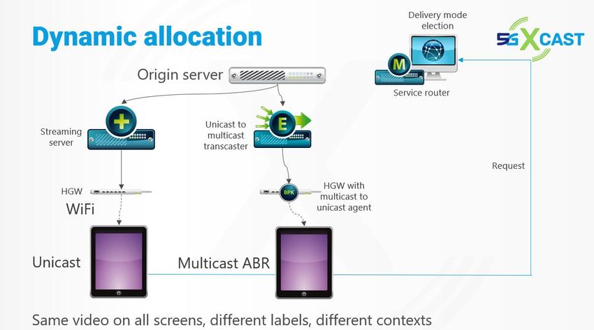
Disclaimer
 This 5G-Xcast deliverable is not yet approved nor rejected, neither financially nor content-
 wise by the European Commission. The approval/rejection decision of work and resources
 will take place at the Interim Review Meeting planned in September 2018, and the Final
 Review Meeting planned in 2019, after the monitoring process involving experts has come to
 an end.

5G-Xcast_D6.2

Executive Summary
This document presents the nine demonstrators and a showcase developed within WP6
of the 5G-Xcast project. The sections for each of the nine demonstrators first discuss the
concept of the demonstrator itself. This is done in the context of the use cases. The
sections then contain a technical description. The development plan is then presented
with a timeline. Finally, a record of the events attended by each demonstrator is given.
The document is concluded with some information on the 5G-Xcast Showcase at the
European Championships 2018.
The demonstrators predominantly cover use cases belonging to the two verticals: Media
and Entertainment, and Public Warning. A summary of both the Media and Entertainment
Hybrid Broadcast and the Multimedia Public Warning use cases are given in this
document. The demonstrators are targeted at selected events (for example EuCNC
2018, IBC 2018, MWC 2019 and EuCNC 2019). Furthermore, a showcase was
organized in connection with the European Championships 2018 to demonstrate the
Hybrid Broadcast Service.
In Section 2.1 IRT and EBU present their demonstrator, which targets the Media and
Entertainment Hybrid Broadcast Service use case. This demonstrator is focused on the
delivery of live TV and the access to additional on-demand content on mobile phones
and TV-sets.
In Section 2.2 Broadpeak present their multicast Adaptive Bitrate (mABR) demonstrator,
which is in collaboration with the Sat5G project from 5G-PPP Phase 2. This
demonstrates caching and multicast content/VNF distribution to the edge over satcom,
using low latency with mABR Live streaming and OTT Streams Synchronization.
In Section 2.3 Fairspectrum and TUAS present their spectrum management
demonstrator, using a spectrum manager developed by Fairspectrum. This targets the
Public Warning vertical.
In Section 2.4 Expway, IRT and EBU present their demonstrator, which shows a 5G
network able to switch between unicast to broadcast according to user demands to
optimise spectrum resources by the implementation of MBMS operation on Demand
(MooD).
In Section 2.5 BLB, in collaboration with IRT, present their demonstrator, which shows a
unicast stream being received via LTE and Wi-Fi interfaces, with a seamless switch
between them and the ability to increase aggregated throughput via Multi-Link.
In Section 2.6 BT and Expway present their demonstrator in which the live, unmodified,
BT Sport commercial service can be integrated using the 5G-Xcast content distribution
framework to benefit from multicast/broadcast distribution. It shows content prepared for
unicast distribution being distributed over both fixed and mobile networks with dynamic
switching between multicast/broadcast and unicast delivery as the audience size
changes.
In Section 2.7 the BBC present their demonstrator, which shows an object-based
approach to content delivery. The content will be delivered as a number of objects over
multicast (using the DASM system) and unicast. The user equipment then composites
the objects depending upon the environment and user preferences.
In Section 2.8 TUAS, Fairspectrum, LiveU and one2many present their demonstrator,
which targets the Public Warning vertical. They demonstrate using dynamic spectrum
management to send public warning multimedia alerts to the user equipment.

                                            1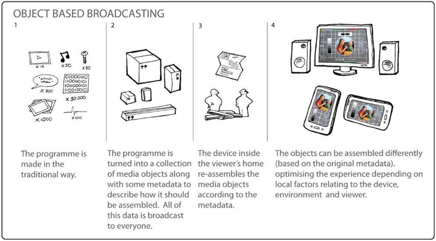
5G-Xcast_D6.2

In Section 2.9 Nomor Research, Bundleslab and Broadpeak present their demonstrator,
which shows the gains and trade-offs in resource consumption, spectrum efficiency,
service coverage, and quality of experience when multicast is introduced as a network
optimization for delivering popular content, and the improvements in the observed trade-
offs achieved by introducing multilink delivery for user equipment with a poor multicast
channel signal.
This is an initial version of this deliverable, and the demo records will be updated once
the demos have been presented. The conclusion, summary and outcome of the demos
will be given in the upcoming Deliverable D6.4.
The following table also collects the deliverables where the final technical concept and
the record of the different events are contained.
 Hybrid Broadcast Service – Linear TV with Add-On Content      D6.5
 Low latency mABR live streaming joint demo with SaT5G         D6.6 / D6.9
 Spectrum Management Demonstrator                              D6.8
 Hybrid Broadcast Service “with MBMS on Demand (MooD)”         D6.7
 Hybrid Broadcast Service “with Multi-Link”                    D6.9
 Converged, autonomous MooD in fixed/mobile networks           D6.9
 Object-based Broadcast across a 5G Core network using Dynamic D6.9
 Adaptive Streaming over IP Multicast
 Multimedia Public Warning                                     D6.9
 Reliable Multicast Delivery in 5G Networks
 5G-Xcast Showcase – European Championships 2018               D6.5

                                           2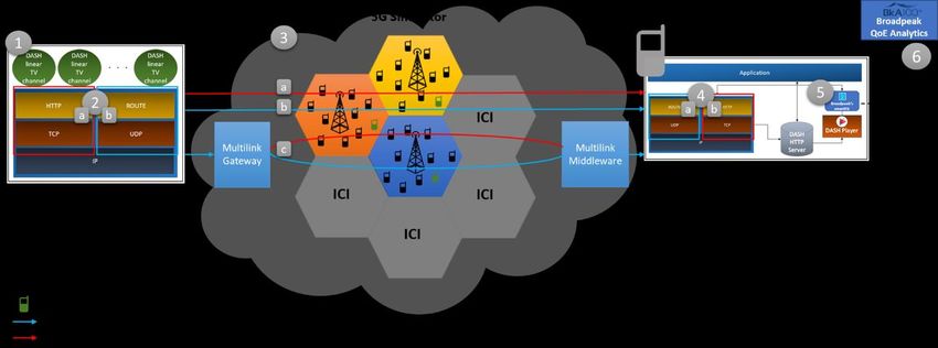
5G-Xcast_D6.2

Table of Contents
Executive Summary ...................................................................................................... 1
Table of Contents ......................................................................................................... 3
List of Figures ............................................................................................................... 5
List of Acronyms and Abbreviations .............................................................................. 6
1      Introduction ............................................................................................................ 7
    1.1      Corresponding use cases ............................................................................... 8
2      Demonstrators ..................................................................................................... 11
    2.1      Hybrid Broadcast Service – Linear TV with Add-On Content ........................ 11
       2.1.1        Concept and Relation to the Use Cases ................................................ 11
       2.1.2        Technical Description ............................................................................ 11
       2.1.3        Development Plan and Events ............................................................... 13
    2.2      Low latency mABR live streaming joint demo with SaT5G ............................ 14
       2.2.1        Concept and Relation to the Use Cases ................................................ 14
       2.2.2        Technical Description ............................................................................ 15
       2.2.3        Development Plan and Events ............................................................... 20
    2.3      Spectrum Management Demonstrator .......................................................... 22
       2.3.1        Concept and Relation to the Use Cases ................................................ 22
       2.3.2        Technical Description ............................................................................ 24
       2.3.3        Development Plan and Events ............................................................... 29
    2.4      Hybrid Broadcast Service “with MBMS on Demand (MooD)” ........................ 32
       2.4.1        Concept and Relation to the Use Cases ................................................ 32
       2.4.2        Technical Description ............................................................................ 33
       2.4.3        Development Plan and Events ............................................................... 34
    2.5      Hybrid Broadcast Service “with Multi-Link” .................................................... 35
       2.5.1        Concept and Relation to the Use Cases ................................................ 35
       2.5.2        Technical Description ............................................................................ 35
       2.5.3        Development Plan and Events ............................................................... 38
    2.6      Converged, autonomous MooD in fixed/mobile networks.............................. 38
       2.6.1        Concept and Relation to the Use Cases ................................................ 38
       2.6.2        Technical Description ............................................................................ 39
       2.6.3        Development Plan and Events ............................................................... 41
    2.7   Object-based Broadcast across a 5G Core network using Dynamic Adaptive
    Streaming over IP Multicast..................................................................................... 43
       2.7.1        Concept and Relation to the Use Cases ................................................ 44
       2.7.2        Technical Description ............................................................................ 46
       2.7.3        Development Plan and Events ............................................................... 47
    2.8      Multimedia Public Warning ........................................................................... 48

                                                                3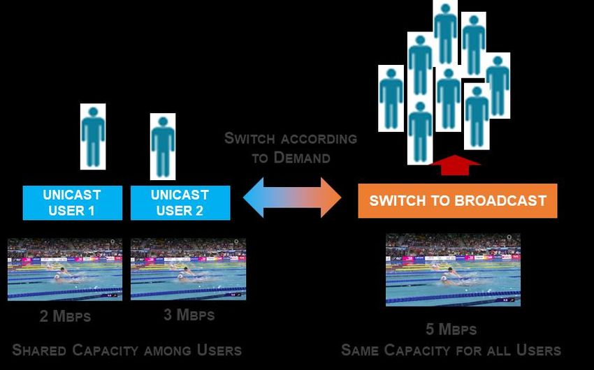
5G-Xcast_D6.2

      2.8.1        Concept and Relation to the Use Cases ................................................ 48
      2.8.2        Technical Description ............................................................................ 49
      2.8.3        Development Plan and Events ............................................................... 50
    2.9      Reliable Multicast Delivery in 5G Networks ................................................... 51
      2.9.1        Concept and Relation to the Use Cases ................................................ 51
      2.9.2        Technical Description ............................................................................ 52
      2.9.3        Development Plan and Events ............................................................... 54
3     5G-Xcast Showcase – European Championships 2018 ....................................... 56
    3.1      The scope of the showcase – Initial considerations ...................................... 56
    3.2      Agreed Technical concept ............................................................................ 57
A     Appendix: Demonstration and showcase planning guidelines .............................. 60
    A.1      Planning Guidelines ...................................................................................... 60
References ................................................................................................................. 62

                                                              4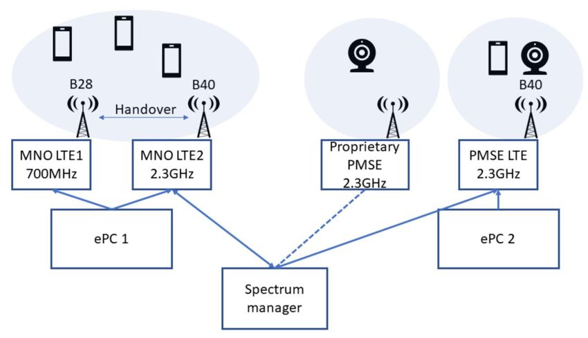
5G-Xcast_D6.2
List of Figures
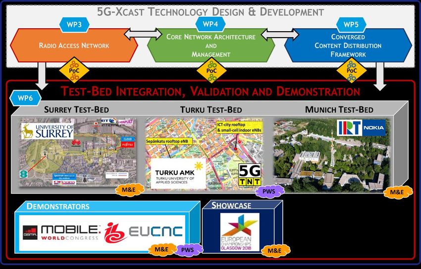
Figure 1. WP6 Scope: 5G-Xcast Test-bed Integration, Validation and Demonstration. . 7
Figure 2: Hybrid Broadcast service use case, showing combinations of networks and
technologies give a seamless experience as the user moves between different locations
..................................................................................................................................... 8
Figure 3: Multimedia Public Warning alert use case ...................................................... 9
Figure 4: ARD Startleiste (Launcher) and HbbTV version of the ARD Mediathek........ 12
Figure 5: General layout for the mABR joint demo with Sat5G .................................... 16
Figure 6: Efficient Edge Content Delivery through satellite .......................................... 16
Figure 7: Smoothen traffic with multicast..................................................................... 17
Figure 8: Usage of mABR with CMAF & CTE enables to reach a lower latency than
traditional IPTV ........................................................................................................... 18
Figure 9: How to solve the desynchronization between User Equipments?................. 19
Figure 10: OTT Stream Synchronization principle ....................................................... 19
Figure 11: Dynamic allocation using the Service Router – BPK proposal .................... 20
Figure 12: Demo of the concept at IBC 2018 .............................................................. 20
Figure 13: EUCNC18 Spectrum management demonstration ..................................... 25
Figure 14: EUCNC19 Coexistence video demonstration ............................................. 27
Figure 15: EUCNC19 Coexistence multi-choice algorithm .......................................... 28
Figure 16: EUCNC19 Spectrum management public warning system demonstration . 29
Figure 17: EUCNC19 Spectrum management public warning system messaging ....... 29
Figure 18: Transmission chain of the demonstrator .................................................... 33
Figure 19: Transmission chain of the demonstrator .................................................... 33
Figure 20: MooD enabling seamless transition between unicast to broadcast and vice
versa ........................................................................................................................... 34
Figure 21: Scenario 1.................................................................................................. 36
Figure 22: Scenario 2.................................................................................................. 37
Figure 23: Multilink demo structure ............................................................................. 37
Figure 24: Main components of the mobile network PoC ............................................ 40
Figure 25: Main components of the fixed network PoC ............................................... 41
Figure 26: Main steps in PoC development ................................................................. 42
Figure 27: Traditional broadcast (top) vs OBB (bottom) .............................................. 44
Figure 28: The origin of the objects in the Forecaster5G demonstrator ....................... 45
Figure 29: Examples of differently rendered content in the Forecaster5G demonstrator
................................................................................................................................... 46
Figure 30: Schematic of the DASM system. ................................................................ 46
Figure 31: Schematic of the Forecaster5G Android application ................................... 47
Figure 32: PoC architecture ........................................................................................ 49
Figure 33: Architectural diagram of the demonstration ................................................ 52
Figure 34: Transmitter chain for showcase ................................................................ 58
Figure 35: Receiver chain for showcase .................................................................... 59
5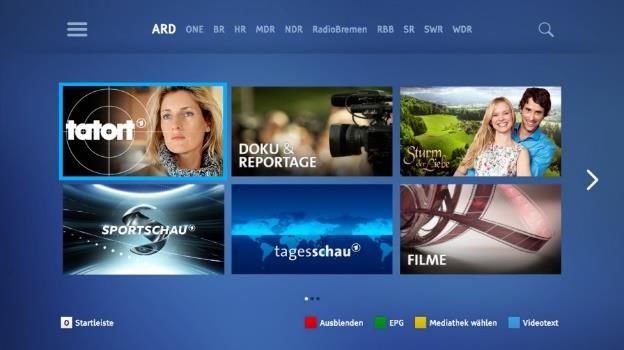
5G-Xcast_D6.2

List of Acronyms and Abbreviations

ABR      Adaptive Bitrate
AIT      Application Information Table
AL       Adaptation Layer
BC       Broadcast
BW       Bandwidth
CDN      Content Delivery Network
DASH     Dynamic Adaptive Streaming over HTTP
DVB-T    Digital Video Broadcasting – Terrestrial
DVB-SI   Digital Video Broadcasting – Service Information
eMBMS    Enhanced MBMS
eNB      Enhanced Node B
EPC      Evolved Packet Core
EPG      Electronic program guide
FLUTE    File Delivery over Unidirectional Transport
GW       Gateway
HD       High Definition
HDR      High Dynamic Range
HFR      High Frame Rate
HTTP     Hypertext Transfer Protocol
HW       Hardware
IP       Internet Protocol
LSA      Licensed Shared Access
LTE      Long-Term Evolution
mABR     Multicast ABR
MBMS     Multimedia Broadcast Multicast Service
MC       Multicast
MEC      Multi-Access Edge Computing
ML       Multi-link
MNO      Mobile Network Operator
MPEG     Moving Picture Experts Group
MW       Middleware
NFV      Network Functions Virtualisation
OBB      Object-based Broadcasting
OFDM     Orthogonal frequency-division multiplexing
OTT      Over-the-Top
PMSE     Programme Making and Special Events
PW       Public Warning
PWS      Public Warning System
QoS      Quality of Service
RAN      Radio Access Network
SDN      Software Defined Network
SDR      Software Defined Radio
STB      Set-top-box
SW       Software
TCP      Transmission Control Protocol
TS       Transport Stream
TV       Television
TVWS     TV White Space
UDP      User Datagram Protocol
UE       User Equipment
UHD      Ultra-High Definition
URL      Uniform Resource Locator
VoD      Video-on-Demand
VPN      Virtual Private Network

                                        6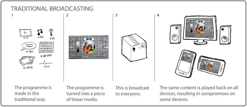
5G-Xcast_D6.2

1 Introduction
This document presents the planning, technical description, and demo record for the
development of showcases, demonstrators and trials that was carried out within WP6 of
the 5G-Xcast project. The overall scope of WP6 and the relation to other work packages
is illustrated in Figure 1.

 Figure 1. WP6 Scope: 5G-Xcast Test-bed Integration, Validation and Demonstration.

In the context of WP6, terminology is considered as follows.
A test-bed is a platform for development and testing of 5G solutions, including hardware,
software, protocols, applications, measurement equipment, and validation tools. It may
include both a laboratory environment and field test capabilities. Three complementary
test-beds are available in 5G-Xcast: IRT/Nokia in Munich, 5GIC in Surrey, and TUAS in
Turku.
A demonstrator is a specific arrangement of hardware, software, protocols and
applications that aims to show the desired functionality of parts of a system but not
mature enough to be integrated in a test-bed. 5G-Xcast demonstrators are foreseen to
illustrate six different novel concepts:
         • hybrid broadcast service
         • object-based broadcasting
         • public warning system
         • RAN optimisation
         • dynamic unicast – multicast - broadcast allocation
         • spectrum sharing
A trial is equivalent to a demonstrator but implemented in a test-bed and may include a
field test with an on-air signal and the capability to interact with commercially available
equipment such as smartphones, tablets etc. A trial is usually a testing of the new
solution for a limited period of time.

                                            7
5G-Xcast_D6.2
A demonstration is a practical proof of a technical concept or a functionality that has
been implemented either as a demonstrator or in a test-bed. A demonstration can be
internal or public. In 5G-Xcast several public demonstrations were foreseen in
connection with the large events such as:
• IBC 2018
• MWC 2019
• EuCNC 2018
• EuCNC 2019
In addition, a showcase in connection with the European Championships 2018 will
include a demonstration of hybrid broadcast service in the Munich test-bed.
The present document will concentrate on the development of showcases and
demonstrators within the project.
1.1 Corresponding use cases
In the Media and Entertainment Hybrid Broadcast use case (see Section 2.3.1 in [4])
users have access to diverse linear and non-linear video, audio and text media coming
from various sources, personalised and combined with social media, location-based
features and interactivity. This could include linear and on-demand video and audio,
social media, and interactive advertising being consumed on user equipment (UE) that
range from fixed TV sets, mobile devices, and vehicle mounted devices. The access to
this content and these services is enabled for a possible population of millions of
concurrent viewers over a wide variety of environments and contexts such as indoors,
over large geographic areas, and at venues (for example live sporting events). This has
the benefit of giving the end users seamless access to audio and visual content delivered
seamlessly across multiple networks, while giving the content service providers the
ability to deliver this via standard interfaces (thus reducing the implementation complexity
and costs). Additionally, network operators can benefit from a more efficient use of
network resources.
Figure 2: Hybrid Broadcast service use case, showing combinations of networks and
technologies give a seamless experience as the user moves between different
locations
85G-Xcast_D6.2
The Multimedia Public Warning alert use case (see Section 2.4.1 in [4]) allows users in
a targeted location to be notified with alerts carrying text, audio, video and other data
types. For example, an alert for a missing child might include both text and a picture of
the child, thus enhancing the alert in a way not possible when limited to a purely text-
based alert. The multimedia approach may also allow disabled people to interact with
the alert, for example by providing audio for visually impaired people. This is a
Government or community service, connecting to users who have configured their user
equipment (UE) to receive the type of alert, with devices ranging from mobile devices to
devices for home usage only. Due to the nature of public warning, the network may also
be experiencing significantly increased traffic, or even damage. This type of multimedia
alert has the benefit of potentially faster and more informed responses or actions from
members of the public, whilst being able to better include both able-bodied and disabled
people.
Figure 3: Multimedia Public Warning alert use case
The requirements for the Media and Entertainment Hybrid Broadcast, and Multimedia
Public Warning use cases can be found respectively in Sections 2.3.1 and 2.4.1 in [4]; a
summary is given here.
• The user should have a seamless experience on the move, including mobility
between networks and UEs.
• The network resources should grow much less than linearly with audience size,
particularly for large audiences of popular content.
• It should be possible for different network types to carry different content
elements of a single user experience.
• The best available network should be used.
• The UE should be able to consume broadcast/multicast (BC/MC) and unicast
(UC) content simultaneously.
• Content at different quality of experience (QoE) levels should be supported for
different portions of the population in the same geographical area.
• Transition between BC/MC and UC should be optimized.
• Both conventional and object-based delivery should be enabled.
• Latency requirements should not be perceivable to the users.
• The interface between the content provider and the networks should be
consistent, simple and transparent to the content provider.
95G-Xcast_D6.2
• The solution should be flexible enough to allow usage under different network
frameworks.
In addition, the public warning use case requires a high level of reliability.
105G-Xcast_D6.2
2 Demonstrators
2.1 Hybrid Broadcast Service – Linear TV with Add-On Content
2.1.1 Concept and Relation to the Use Cases
IRT, in collaboration with the EBU, targets the development of a demonstrator focused
on the Hybrid Broadcast Service use case defined in [4].
The proposed demonstrator involves several technical features to show the potential of
5G for media delivery in a hybrid fashion, combining:
- The ability to convey traditional always-on linear TV services in state-of-the-art
formats.
- On-demand content, event related information and access to social media.
Live TV content and the signalling for add-on services based on the HbbTV standard are
both included in an MPEG-2 TS and transmitted over the
LTE eMBMS network. The broadcast signal is received by stationary
eMBMS-enabled TV receivers and by smartphones simultaneously, without the need of
unicast connectivity.
Users can access additional on-demand content either via a HbbTV application on TV
sets or a HTML-based application on mobile phones. The on-demand content is
delivered over the LTE unicast link in the mobile network.
The demonstrator highlights aspects such as:
- fixed/mobile convergence,
- combined use of unicast and broadcast capabilities on the same device,
- use of standardized 3GPP interfaces to deliver MPEG-2 TS including live TV
programmes and HbbTV service information,
- free-to-air reception,
- reception on both mobile/portable user devices and stationary TV-sets.
2.1.2 Technical Description
The HbbTV concept, which is currently based on Digital Video Broadcasting (DVB)
broadcast along with an auxiliary broadband connection, is extended to a framework in
which the broadcast signal is carried over an LTE eMBMS session and the access to
unicast data is provided with LTE unicast. Target receivers under consideration are
smartphones and tablets as well as TV-sets.
MPEG-TS is specified as a container format to encapsulate audio and video streams
together with programme and system information. Three TV programmes were
encapsulated with one of them linked to HbbTV service information.
HbbTV services are available on many of the current set-top boxes and TV sets. The
HbbTV services require a user device to be simultaneously connected to both a
conventional broadcast network (i.e. DVB family of terrestrial, cable or satellite broadcast
standards) and broadband network, which is usually integrated by common Ethernet
and/or Wi-Fi interfaces. The project will explore the capability of the current and future
3GPP based 4G/5G specifications to provide a HbbTV service. The main video feed
(linear TV) will be delivered as a DVB-SI compliant TS (MPEG2-TS). The type of services
delivered through HbbTV could be: Enhanced Teletext, Catch-up services, Video-on-
demand, EPG, Interactive advertising, etc.
115G-Xcast_D6.2
Figure 4: ARD Startleiste (Launcher) and HbbTV version of the ARD Mediathek
The screenshots in Figure 4 show the red button application and the catch-up service
ARD Mediathek which are available through all ARD broadcast channels (e.g. “Das
Erste”). Similar HbbTV services are offered nowadays by all major broadcasters in
Europe.
HbbTV services are signalled through the linear broadcast service in the so-called
application information table (AIT), the application shown in the left part of Figure 4 is
marked as autostart and automatically loaded when the user tunes in to the broadcast
service. Loading a HbbTV application means that the initial HTML page is loaded into
the browser and waits for user interaction. Typically, HbbTV applications are activated
when the user presses the red button on the remote control.
Two different HbbTV applications were developed, one meant to be displayed on a TV-
set and another to be displayed on a smartphone.
Whilst the key enablers for this demonstration are included in 3GPP Release 14 (EnTV)
the compliant equipment, chipsets and other components are not yet available.
Therefore, the starting point is the current (pre-release 14) equipment already available
at IRT.
A scheme of the demo setup is shown below highlighting (from 1 to 5) the different steps
and functionalities implemented.
1 3
OrgID App2 REPOSITORIES
AppID App2 Internet http://server1
URL http://server2 SIGNALING
OrgID App1
http://server2
AppID App1
URL http://server1 2
EPC DOWNLINK SIGNAL
eNodeB
MBSFN UC
M EDIA STREAMING 700 MHZ BAND
rtp://x.x.x.x:x MBMS
CONTENT PROVISION AND HBBTV
ORCHESTRATION EPC/MBMS AND RADIO STACK
SMARTPHONE 4
rtp://x.x.x.x:x
A) LIVE TV BROADCAST RECEPTION http://server1
B) LIVE TV BROADCAST + UNICAST (HBBTV)
TV-SET rtp://x.x.x.x:x
http://server2
A) LIVE TV BROADCAST RECEPTION 5
B) LIVE TV BROADCAST + UNICAST (HBBTV)
MPEG-TS
Multicast Unicast FORWARDING
125G-Xcast_D6.2
1. Content is provided by the EBU from the European Championships venues.
Encapsulated in a MPEG-2 TS alongside live TV programmes, HbbTV signalling is
inserted pointing to additional on-demand content offered by the broadcaster.
2. A small-scale computer-based solution including LTE EPC, MBMS and radio stack
permits the delivery of the broadcast signal (MPEG-2 TS over RTP) over LTE
downlink and the allocation of the remaining unicast capacity for on-demand traffic.
3. Internet connectivity provides access to the servers with on-demand content.
Broadcasters can direct users to their own content repositories.
4. Smartphones with Expway’s middleware allow users to watch live TV programmes
via the broadcast system and on-demand content via a mobile web application and
a unicast internet connection.
5. A smartphone acting as a set-top-box forwards the original MPEG-2 TS to a TV-set
that can tune in to the live TV signal with the possibility to access HbbTV services.
2.1.3 Development Plan and Events
This demonstrator is initially targeted for the IBC conference taking place in Amsterdam
in September 2018.
The development of the concept proposal was considered in the first phase, by
specifying the technological aspects to be shown in the demonstrator. This involves the
definition of the HBS to be implemented and the aspects related to user experience. A
second step consists of preparing the necessary hardware and equipment for the
demonstrator, as captured in the Demo Record below. The development of the
demonstrator requires the preparation of a test signal which will already contain an
MPEG-TS with associated service information and HbbTV signalling. This will help to
determine an adequate data rate for the final demonstrator as well as assist the
development of the app for the smartphone and the HbbTV app to be displayed on a TV-
set, as per the subsequent steps in the development. The final MPEG-TS will be
generated, taking advantage of the content provided by the EBU for the European
Championships, to which the add-on information for the HbbTV applications will be
linked.
2018
J F M A M J J A S
Concept Proposal
Hardware & Equipment preparation
Test signal generation
Smartphone App development
HbbTV App development
Branding Insertion
Final content generation
End-to-End testing
Demonstrator Finalized
At the time of completion of this deliverable, the demonstrator has been successfully
shown at the following events:
- IBC Conference 2018
- Medientage 2018
- EBU Forecast 2018
DEMO RECORD
135G-Xcast_D6.2
Hardware involved in the demonstrator
- Amarisoft eNB+MBMS GW
- IP Router
- TV-set
- Local HbbTV web-server (external PC)
- 4 UEs with eMBMS middleware
Software components
- Smartphone application integrating access to MBMS API and Android API
- HTML application for add-on content display in the smartphone
- HbbTV standard-compliant application for TV-set
Content description
- MPEG TS containing 3 linear TV services and 2 HbbTV applications (1 to be
displayed in the smartphone, a second to be displayed in the TV)
Event 1. IBC 2018
Place Amsterdam
Date
Audience Worldwide broadcasters, content creators/providers,
equipment manufacturers, professional and technical
associations
Event 2. Medientage 2018
Place Munich
Date 24-26 October
Audience German media and communication industry
Event 3. EBU Forecast
Place Geneva
Date 19-21 November
Audience European broadcasters and broadcast industry
The complete information about the finalized demonstrator will be found in D6.5.
2.2 Low latency mABR live streaming joint demo with SaT5G
2.2.1 Concept and Relation to the Use Cases
This joint demo with Sat5G aims:
- To demonstrate caching and multicast content/VNF distribution to the edge over
satcom, using low latency with Multicast Adaptive Bitrate (mABR) Live streaming and
OTT Streams Synchronization.
- To address the Media & Entertainment use case 1: Hybrid broadcast service.
Several requirements have been defined for each use case in D2.1, see [4].
The mABR Demonstrator meets the following requirements related to Use Case M&E1:
145G-Xcast_D6.2
- The user’s device is able to automatically connect to the best available network to
give the highest QoE to the user.
- The network resources required to deliver the service to a given audience should
grow much less than linearly with audience size, particularly for large audiences of
very popular content.
o Minimizing the distribution costs for the content service provider
- The 5G-Xcast solution should be scalable to allow nationwide network coverage (e.g.
>99 % of the populated areas, roads and railways), noting that capacity requirements
are not uniform throughout the coverage area and may substantially differ across
rural, sub-urban, and urban areas, as well as in crowded venues and hotspots. This
means that the number of services of a given type to be provided in a given territory
at the same time should be scalable.
- The 5G-Xcast solution should allow indoor, outdoor and in-vehicle coverage.
- The 5G-Xcast solution should be able to provide a sufficient data rate to deliver
content up to UHD quality.
- Latency:
o End-to-end latency is allowed to be in the order of 50ms or even higher.
▪ Delay from live should be no worse than other delivery methods.
o Difference in delay between different streams on the same device shall.
not be perceivable by the users.
o Channel change latency should be of the order of 1 second, not excepting
additional contributions from latencies that may be outside the scope of
the 5G-Xcast system such as communication with a decryption key
server.
2.2.2 Technical Description
The device will receive Live channels either from satellite feed or broadband depending
on the decision of the Service Router.
Channel delivery over satellite is done using mABR to optimize bandwidth usage.
CMAF & CTE packaging mechanisms are used to reduce latency.
The Nano Content Delivery Network (CDN) agent enables the synchronization of the
streams between the devices at the Home Gateway level.
155G-Xcast_D6.2
Figure 5: General layout for the mABR joint demo with Sat5G
All head-end servers are hosted at the 5GIC test bed in Surrey. This prototyping platform
is managed by the University of Surrey.
Efficient Edge Content Delivery through satellite
Broadpeak will focus the demonstration on using Satellite Multicast capabilities for the
delivery of live OTT channels. Broadpeak will also demonstrate low latency with a mABR
Live streaming using CMAF/CTE and OTT Streams Synchronization to improve user
experience.
Figure 6: Efficient Edge Content Delivery through satellite
2.2.2.1.1 Low Latency using mABR, CMAF & CTE
Understanding Latency:
165G-Xcast_D6.2
Video services delivered over IPTV or Cable TV managed networks typically experience
low delay because there is guaranteed BW and a requirement for limited buffering in the
set-top box (STB). For HTTP video streaming, it’s a whole different scenario.
Secondary screens such as connected TVs, smartphones, and tablets are accessible on
various unmanaged networks (i.e., 3G, 4G and OTT) where traffic is irregular. In order
to ensure a good quality of experience without constant playout interruptions, players
need to buffer a high quantity of video. This is what creates a high delay.
Apple recommends that HLS video chunks last six seconds, and three chunks are
usually buffered in the players, implying an extra 18 seconds delay. Some Android
players even require five MPEG-DASH chunks buffered in the player, meaning the delay
can be longer than 30 seconds.
The Power of Multicast Technology:
By using mABR technology at the CDN level, operators can successfully stream video
without needing to buffer massively on the player side to guarantee a good quality of
experience. The solution involves deploying a unicast-to-multicast transcaster in the
head-end and multicast-to-unicast agents in the Customer Premises Equipment (CPE)
to bring the latency down to only a few seconds instead of the typical 30 seconds.
Figure 7: Smoothen traffic with multicast
Beyond employing mABR technology at the CDN level, there are additional steps
operators can take to reduce latency. They can employ the low latency flavor of Common
Media Application Format (CMAF) during packaging and rely on chunked transfer
encoding. CMAF allows the creation of small 250ms chunks and chunked transfer
encoding enables the processing of fragments on the fly before they are fully received.
On the player side, operators need to adapt the volume of content to buffer to content.
In this scenario, they would only buffer one second of video in the home network for good
quality and low latency, and buffer more chunks in mobility to ensure good quality,
although with longer latency.
It’s important to note that the additional steps mentioned above (i.e., CMAF, chunked
transfer encoding) will not allow operators to achieve low latency by themselves. Without
mABR technology, the video quality will suffer dramatically due to constant rebuffering.
mABR is unique because it uses the same network as traditional IPTV and prioritizes
traffic inside the network. The jitter inside the network is very low, hence only limited
buffering is required in the device.
175G-Xcast_D6.2
Figure 8: Usage of mABR with CMAF & CTE enables to reach a lower latency than
traditional IPTV
2.2.2.1.2 Stream synchronization
In different use cases, several receivers close to one another may be in the situation
where they play the same live content, for example:
• People following a show with various receivers, so that they can walk freely
throughout their home and still keep an eye on their program.
• Bars or communities showing a sport event via several screens.
Whenever this happens, it is important that all displays are synchronized, so that they all
show the same point in time naturally, but even more importantly so that the audios don’t
interfere with each other, which can be particularly annoying for the human ear. Note
that traditional Broadcast, where the same content is pushed to all users, does provide
synchronization between screens while it is not the case for default OTT, which might be
seen as a regression when migrating to a full OTT system.
Broadpeak mABR solution enables synchronizing all the devices connected on the same
nanoCDN gateway to create a better user experience.
185G-Xcast_D6.2
Figure 9: How to solve the desynchronization between User Equipments?
Figure 10: OTT Stream Synchronization principle
Waiting for the next segment allows sync between players in the house + optimized
latency vs source stream. The drawback is a slower zapping time but this choice is
configurable per channel.
Hybrid Broadcast Service
Users have access to audio-visual content and services delivered over a combination of
several networks simultaneously. In order to provide a seamless user experience, the
content is made available on different types of devices either at home or outdoor,
including stationary and mobile conditions. The user’s device is able to automatically
connect to the best available network to give the highest QoE to the user.
Different transport modes are used to enable this seamless user experience. Depending
on the user context, the audio-visual content can be delivered through unicast or
multicast ABR. The audience of a media is one of the triggers to switch between unicast
and multicast ABR.
195G-Xcast_D6.2
Figure 11: Dynamic allocation using the Service Router – BPK proposal
2.2.3 Development Plan and Events
A first step of the demo was showcased at the IBC 2018. Due to constraints related to
the IBC show (short setup time, Wi-Fi congestion) it has been decided that we make a
descriptive demo of the concept in order to focus on the messaging.
Figure 12: Demo of the concept at IBC 2018
A collaboration between Sat5G and 5G-Xcast projects has been initiated and will lead to
a joint demo related to the media and entertainment vertical. The plan is to have this
demo showcased at the EuCNC 2019 in Valencia. Within Sat5G, a use case focuses on
the usage of satellite to convey live video content to mobile edge nodes in multicast in
order to optimize the backhaul usage or even to replace it in regions where the
infrastructure does not exist. The availability of this multicast contribution stream could
be an element taken into account within 5G-Xcast in the convergent video delivery use
case. The video content could be delivered from the edge node where it has been made
available either in multicast via satellite, or in unicast using the broadband network to the
end-users, as described in the use case and based on the context of each request. The
service router concept defined in 5G-Xcast would be fed by content availability
205G-Xcast_D6.2
information provided within Sat5G. This would lead to an end-to-end optimized delivery
of video content on 5G mobile networks.
2018 2019
A S O N D J F M A M J
Concept proposal
Solution development (Software dev)
Hardware preparation at Surrey – Phase 1
Setup remote access between UoS - iDirect – Broadpeak
Install Bpk SW in UoS (Alpha version)
Install iDirect SW in UoS
Setup (VPN) between teleport and UoS for data path
Install iDirect HW in UoS
Upgrade Bpk SW in UoS (Beta version)
Initial Test over Broadband
Satellite link available
End to end testing on Satelitte
Demonstrator finalised
DEMO RECORD
Partners involved
- Avanti
- Broadpeak
- iDirect
- University of Surrey
Hardware involved in the demonstrator
- iDirect Satellite Home Gateway
- IP Router
- USB ethernet adapter (Lava eSTS-E)
- TV-set
- Android Set-top box
- Android Tablets
- VMWare ESXi Host
Software components
- Broadpeak Origin Server (BkS350)
- Broadpeak Transcaster (BkE200)
215G-Xcast_D6.2
- Broadpeak Streamer (BkS400)
- Broadpeak Analytics server (BkA100)
- Broadpeak Service Router (umbrellaCDN)
- Broadpeak multicast to unicast agent (nanoCDN)
- Broadpeak Mediator (BkM100)
Content description
- 1 live channel streamed simultaneously in mABR over a satellite link and in
unicast through a broadband network. The mABR live channel will be displayed
on a TV set and on a tablet in order to demonstrate OTT Stream
Synchronization. The unicast live channel be displayed on a tablet in order to
demonstrate low latency (the unicast stream being displayed with a higher
latency than the mABR stream).
Event 1. IBC 2018
Place Amsterdam
Date 14-18 September 2018
Audience 630 people
Event 2. EuCNC 2019
Place Valencia
Date 18-21 June 2019
Audience
The complete information about the finalized demonstrator will be found in D6.6.
2.3 Spectrum Management Demonstrator
The dynamic spectrum management and spectrum sharing demonstrators in 5G-XCast
project are Dynamic spectrum management and spectrum sharing demonstrator in
EUCNC 2018, coexistence management demonstrator in Turku and displayed as a video
in EUCNC 2019, and a Public warning demonstrator combined with spectrum
management in EUCNC 2019.
2.3.1 Concept and Relation to the Use Cases
The demonstrators verify the XCast solution for the requirement M&E1_R38 and
M&E3_R1 (see [4]): “The 5G-Xcast solution should be flexible enough to allow operation
under different spectrum usage frameworks.” This aspect can be considered to relate to
several use cases, whenever dynamic spectrum use is required. The technical solution
being tested is a spectrum manager developed by Fairspectrum. This is in addition to
the requirement 31 regarding supported frequency band flexibility. In mainstream
exclusive spectrum, the 5G-XCast solutions work without specific spectrum
management issues. Due to that, the spectrum management demonstrators concentrate
on unlicensed spectrum, where coexistence management can improve the reliability of
the 5G-XCast solutions, and on shared spectrum, where the selected sharing framework
and related rules can accommodate a wide variety of QoS classes and service levels
ranging from opportunistic access like on unlicensed spectrum to prioritized exclusive
spectrum use.
The first demonstrations were related to the use cases M&E1 – Hybrid broadcast service
and especially M&E3 – Remote live production (see [4]). Spectrum sharing between
mobile network operators, a private LTE network (that can be used by a PMSE
stakeholder for production for example) and conventional PMSE equipment was
demonstrated. Spectrum sharing was shown in the EUCNC 2018. The demonstration
225G-Xcast_D6.2
was carried out by Fairspectrum and Turku University of Applied Sciences. 2.3 GHz was
used for wireless camera communications in many European countries. ETSI has
specified how Licensed Shared Access (LSA) helps mobile operators to use the same
spectrum band as a secondary user. A part of the 2.3 GHz Program Making and Special
Events (PMSE) users were expected to migrate the camera communication to LTE or
5G. This demonstration showed how the current license holders, PMSE, can be
prioritized and how LSA can be used to manage spectrum sharing between current
PMSE use, LTE based PMSE use and commercial LTE operator network. Although the
demonstrator was transversal to different use cases, PW1 would benefit from the
features implemented in it in order to evaluate and adapt the transmission to the most
adequate spectrum band for the delivery of PW messages.
The recent development of coexistence management solutions has been concentrated
on three technology families: Wi-Fi (IEEE 802.11), TVWS (802.11af) and CBRS GAA
(WINNF, CBRS Alliance). The most extensive standards work has been carried out in
802.19.1 specifications. As the only native 3GPP technology, we demonstrate the
coexistence management for CBRS GAA, which is the opportunistic access class of the
US LTE band 48. We demonstrate a dedicated coexistence manager responsible for
spectrum management among CBRS users. We study several algorithms for efficient
resource (frequency and power) allocation among CBRS base stations operating as GAA
users in the three-layer model and demonstrate the most potential one. As a part of the
theoretical background study we provide: a detailed mathematical definition of the
resource (power and frequency) allocation problem, a dedicated graph colouring
implementation for spectrum allocation, two extensions of the above-mentioned
algorithm, which deal with the problem of aggregated interference, a multi-choice
algorithm that can be run on the coexistence manager, a solution to the power
optimization problem that guarantees optimal power allocation among GAA base
stations for a given frequency allocation scheme, and an analysis of the trade-off
between power allocation and frequency split in case of interference limitations; mainly
we have derived when it is better to reduce transmit power and keep the assigned
frequency band unchanged, and when it is better to keep the transmit power unchanged
and split orthogonally frequency band among base stations. The proof-of-concept in
Turku is carried out managing the transmission BW only, and the PoC is carefully
recorded, edited, and shown at EuCNC as a video.
The Public Warning demonstrator is aimed at developing part of the concepts
investigated in the project (in WP3 and WP4) in order to deliver multimedia public
warning messages with high reliability and coverage. The current Public Warning
Systems are able to reach the target audience well with text messages and notifications
in broadcasts. EMBMS is a multimedia broadcasting system, which can broadcast
multimedia content over mobile networks to supporting mobile devices. Dynamic
Spectrum management allows changes in spectrum capacity locally and temporarily.
The EuCNC demonstrated system contains an administrative interface to create a PWS
message and select the channels, time, and coverage. In this demonstration, a new
spectrum resource is defined and created simultaneously with the message. Before
sending the message, the spectrum resource for eMBMS is created using dynamic
spectrum management. The PWS system sends a PWS multimedia message over an
available channel to the mobile device. In addition to the multimedia warning, the
message contains a trigger to an eMBMS PWS feed, which uses the dynamically created
spectrum resource. The system creates an LTE channel in the 700 MHz band. The
trigger message is sent over Wi-Fi. EMBMS content is received in the created LTE
channel by the UE.
235G-Xcast_D6.2
2.3.2 Technical Description
The trial presented in [5] was conducted in Turku University of Applied Sciences testbed
(5GTNT). The 5GTNT testbed focuses on spectra below 6 GHz. Currently the 700 MHz
5G candidate band and the 2.3 GHz Licensed Shared Access (LSA) band are supported
for LTE. Equipment for the 5G candidate band 3.4-3.8 GHz is currently being added to
the testbed. The test network sites are in Turku University of Applied Sciences campus
area in Turku, Finland. The testbed is an integral part of 5G Test Network Finland
(5GTNF) ecosystem, which coordinates the integration of the Finnish 5G testbeds.
The system consists of PMSE equipment operating occasionally on 2.3 GHz band and
an MNO LTE network operating on 700 MHz and 2.3 GHz bands. The latter represents
MNO employing additional capacity on 2.3 GHz band using for example the
supplemental downlink concept. Proprietary PMSE equipment represents an OFDM
based proprietary solution for wireless cameras operating on the band. PMSE LTE is a
rapidly deployable LTE network that can be used for PMSE purposes. Different ePCs
(enhanced Packet Cores) are used for the MNO LTE and PMSE LTE networks. The
ePC2 used for private network is a limited feature core that includes only necessary
components for the data transmission, thus enabling rapid deployment when combined
with a base station.
The spectrum manager orchestrates the operation of the different systems on 2.3 GHz
shared band. PMSE system information is collected with a web based reservation
system. The users of the devices make reservations for their intended use. The
reservation system has been piloted in the Netherlands in 2017-2018. The control of the
PMSE devices also takes place through the reservation system so that the user of the
devices is informed about required spectrum use changes with an email, and the user
has to deploy the configuration changes in the devices. Both PMSE LTE and MNO LTE
systems have a direct machine-to-machine interface between the radio equipment and
the spectrum manager. When the priority user changes the configuration of the LTE
network, a notification about the change is automatically received in the spectrum
manager. The spectrum manager processes the changed spectrum situation and
evaluates if the lower priority use may cause harmful interference to the higher priority
use. If there is a risk of interference, the spectrum manager evaluates which changes
would be required to accommodate the higher priority use and to also maintain the best
possible service level for the lower priority use. On the high level, this is implemented so
that if there are frequency channels available, the lower priority use is transferred to
those channels. If there are no other channels available, the power level of the secondary
user is lowered, or the transmission is denied. In this demonstration, the higher priority
user is able to select the frequency channel to be used. An option for this could be that
the higher priority user has the right to the spectrum resource in the band, but the specific
frequency channel is determined by the spectrum manager. The setup in the laboratory
is shown in Figure 13.
245G-Xcast_D6.2
Figure 13: EUCNC18 Spectrum management demonstration
Coexistence management
The coexistence management proof-of-concept in Turku [7] is carried out for managing
the transmission bandwidth only, and the PoC is carefully recorded, edited, and shown
in EUCNC as a video, see Figure 14.
In coexistence management the Multi-choice algorithm scheme is illustrated in Figure
15. It is split conceptually into two main phases; the first one, where the Graph Coloring
with Add Edge Procedure is applied (Alg. 2), and the second one, where node clustering
is applied iteratively. In the first phase, only one solution is generated, i.e., the one where
all devices transmit with the maximum allowable power (this is obtained by maximal band
fragmentation). In the second phase, the remaining Mmax−1 solutions are created. The
algorithm is discussed below.
1) Initialization and graph coloring: As in the previous algorithms, as the input to the
algorithm we take the limitations coming from the SAS and from the CBSDs
specifications, mainly the maximum equivalent transmit power for each device is
provided. Next, as the parameter we take the acceptable interference level PINT.
We start with the creation of the interference graph and calculation of the
chromatic number X.
2) Phase 1 - Assignment colors to frequency bands: Next the algorithm enters the
step of assignment of frequency subbands to the colors. Currently this is realized
by generation of all X! possibilities and selection of the best one minimizing
number of required guard bands. In particular, we check if each combination of
color pairs can occupy adjacent frequency bands or if they need one channel of
separation as a guard band to prevent excessive out-of-band interference. Next,
we try all combinations of colors pair orderings and search for the one which
requires the minimal number of guard bands. When we know the order of the
colors and the places for the guard bands, we only need to choose how many
channels (subbands) to assign to each color. We used two solutions. The first
one assumes that every color should have the same amount of spectrum. The
second one assumes assignment proportional to number of devices utilizing a
given subband, i.e., colors with a higher number of devices should have more
255G-Xcast_D6.2
spectrum than others. For example, if we have 3 devices associated with 2 colors
(one device to one color, and two devices to the other color), then the first color
should get 1/3 of the spectrum and the second color should get 2/3 of the
spectrum. The former approach is hereafter called Equal assignment, whereas
the latter is hereafter called Proportional Assignment. One may observe that the
order in which coloring and assignment of frequency bands to colors are
performed makes a difference. Thus, it may happen that there are some channels
without a color, for example because the number of channels (without guard
bands) is not always divisible by number of colors X. In such a case we simply
add these free channels to random colors (CBSDs). Observe that the above
described procedure is carried out for each subgraph (not connected to another
subgraph) separately.
3) Phase 1 - Add edge procedure: In order to verify the correctness of the created
graph and resultant frequency assignment, the total observed aggregated
interference (denoted in the algorithm as PINT) is calculated for each node on its
coverage area. If the aggregated interference from many CBSDs violates the
interference constraint it has to be eliminated, and this is done by an application
of the Add Edge algorithm (Algorithm 2), repeated as many times as the
aggregated interference occurs. Once this constraint is fulfilled, the created graph
is treated as the outcome of the first phase of the Multi-Choice Algorithm and
delivered as input to the second phase. One may notice that this graph and its
corresponding chromatic number guarantees interference free transmission with
the maximum power for all I CBSDs. This means that the available spectrum has
to be split into X orthogonal, not necessarily equal (as mentioned in the previous
subsection), subbands of the bandwidth being the integer multiplication of 5 MHz.
If such a division is possible, then we treat such a spectrum assignment as the
first possible solution and store it. The created solution may however not be
possible if the number of CBSDs is large and the interference graph very dense.
To be more precise, when the final chromatic number X is greater than the
number of available 5 MHz channels N, then it is impossible to split the spectrum
as described earlier. In such a case the outcome of the first phase of the algorithm
is the interference graph that guarantees the lack of an aggregated-interference
problem. No possible solution for frequency assignment will be created then.
4) Phase 2 - Iterative procedure: The outcome from Phase 1 of the Multi-Choice
Algorithm is, first, the network graph that may be colored in such a way that there
will be no aggregated interference. Second, the chromatic number X, and third,
if applicable, the unique solution for maximum transmit power. The ultimate goal
of Phase 2 is to show the trade-off between the allocation of power and frequency
to the CBSDs. The algorithm calculates the optimal power assignment for all
potentially applicable numbers of frequency divisions. In other words, it starts with
the case where all CBSDs are clustered together (i.e., they will use the same
frequency or equivalently the number of colors in the graph is one) and optimizes
the transmit power in the network, taking into account each 5 MHz band
individually. If by m we denote the current number of CBSD clusters, then the
algorithm starts with m = 1. Next, the number of colors is incremented, which is
equivalent increasing by one the total number of CBSD clusters (m = 2). In other
words, the entire band will now be split into two parts. Again, the optimal power
assignment is applied. This procedure is repeated Mmax - 1 times, until the
number of clusters equals the chromatic number X or when the number of
clusters equals number of available 5 MHz channels.
5) Phase 2 - Merging Colors: An important issue is to find the method for cluster
creation, mainly, how shall the CBSDs be assigned to the cluster? The method
is chosen in order to decrease spectrum fragmentation. The input is the colored
interference graph from Phase 1. It contains X various colors. In order to achieve
26You can also read