Open Source Espresso Machine for Makers - Department Of Mechanical Engineering
←
→
Page content transcription
If your browser does not render page correctly, please read the page content below
Department
                                          Of
                                          Mechanical
                                          Engineering

              MEng Mechanical Engineering

Open Source Espresso Machine for Makers

                       Zack MOSS

                        April 2019

                       David Polson

 Thesis submitted to the University of Sheffield in partial
     fulfilment of the requirements for the degree of
                  Master of Engineering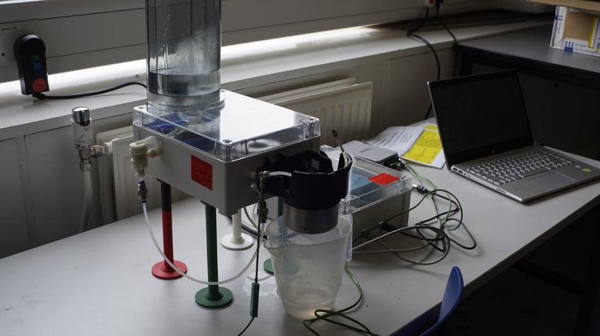
SUMMARY
In the last decade there has been a growing number of open source designs aimed
at makers, which are available for anyone to access, modify, and improve, and can
often be manufactured in a maker space. This project followed a practical-based
design approach to produce the first open source espresso machine. This involved
reverse engineering a consumer-level machine and producing two functional
prototypes, whilst sharing progress and the final documentation with the open
source community. This documentation contains enough information so that anyone
can build the design themselves. The design matched the consumer level machine
in both temperature stability and taste of espresso but lacked the same level of
functionality. The final design produced can be considered the first iteration of a
wider open source project, which can be developed by the maker community.

                                           ii
CONTENTS
  Summary..............................................................................................................................ii
  Contents ............................................................................................................................ iii
  Acknowledgements ......................................................................................................... v
  1 Literature Review ..................................................................................................... 1
  1.1 Introduction to Coffee ......................................................................................... 1
  1.1.1 Overview .................................................................................................................. 1
  1.1.2 Coffee Processing ............................................................................................... 2
  1.1.3 Roasting .................................................................................................................. 3
  1.1.4 Grinding .................................................................................................................. 4
  1.2 Introduction to Brewing Technology ............................................................. 4
  1.2.1 Brewing Methods ................................................................................................ 4
  1.2.2 Espresso Machine Components ....................................................................7
  1.3 Introduction to the Maker Community ....................................................... 16
  1.3.1 History .................................................................................................................... 17
  1.3.2 Current State....................................................................................................... 17
  1.3.3 Open Source ........................................................................................................18
  1.4 Previous work ........................................................................................................ 19
  1.5 Conclusion .............................................................................................................. 19
  2 Design Process........................................................................................................ 20
  2.1 Aims & Objectives ............................................................................................... 20
  2.1.1 Aims ........................................................................................................................ 20
  2.1.2 Objectives ............................................................................................................. 20
  2.2 Methodology........................................................................................................... 21
  2.3 Design Selection ................................................................................................... 21
  2.4 Reverse Engineering ........................................................................................... 24
  2.4.1 User Experience ................................................................................................ 25
  2.4.2 Experimentation ................................................................................................ 26
  2.4.3 Dismantling .......................................................................................................... 28
  2.5 Design Specification ........................................................................................... 29
  2.5.1 Manufacturing Facilities ................................................................................. 30
  2.6 First Prototype ...................................................................................................... 31
  2.6.1 Design ..................................................................................................................... 31
  2.6.2 Testing ................................................................................................................... 34
  2.7 Second Prototype ................................................................................................ 41
  2.8 Documentation for Open Source Design................................................... 44
  3 Conclusion & Discussion .................................................................................... 44
  3.1 The Design Process ............................................................................................ 45

                                                                          iii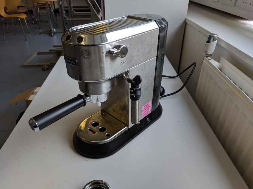
3.2 Evaluation of the Open Source Approach ................................................. 45
3.3 Evaluation of the Espresso Machine ............................................................ 46
3.4 Further Work ........................................................................................................ 47
References ....................................................................................................................... 49
Appendix 1. Prototype photos .................................................................................. 53
Appendix 2. Open source documentation ........................................................... 54

                                                                      iv
ACKNOWLEDGEMENTS
I wish to express my gratitude to my supervisor, Mr. David Polson, for enabling me
to carry out this project, and for his guidance and support throughout.

I sincerely thank the electrical technician staff, Mr. Michael Herbert and Mr. Chris
Todd, for their expertise and assistance in building the espresso machine.

                                            v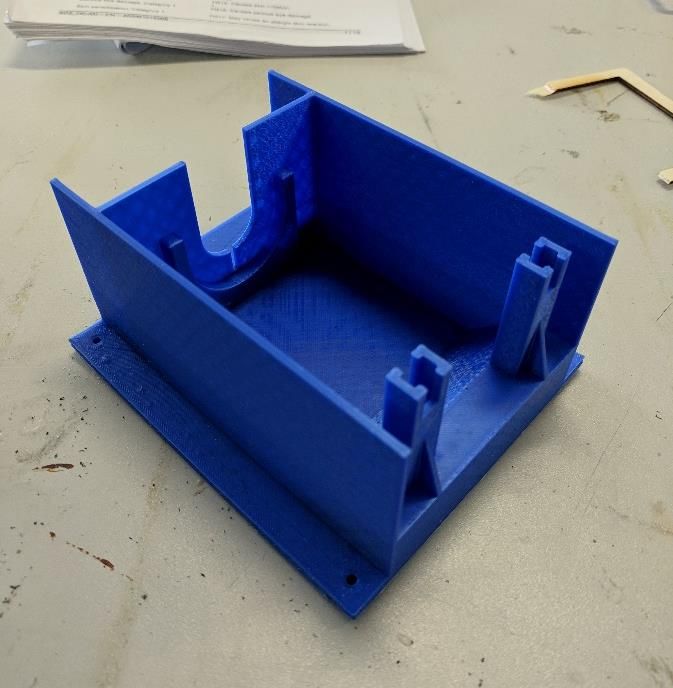
1       LITERATURE REVIEW

1.1     Introduction to Coffee

1.1.1   Overview

Over 2.25 billion cups of coffee are consumed in the world every day (1). That is 800
billion cups per year, with 95 million cups of coffee drunk per day in the UK alone
(2). The coffee industry is worth over $100 billion, the only commodity more sought
for is crude oil (3).

Coffee is drunk all over the world, it is also grown all over the world, in over 50
countries. It is usually grown in countries near to the equator, due to the conditions
that favour growth of the plant. Coffee beans (Figure 1.1 (4)) are dried and roasted
seeds from the cherry of the Coffea tree (Figure 1.2 (5)).

          Figure 1.1 Inside a coffee cherry        Figure 1.2 Coffea Arabica tree

There are two main species of coffee tree that are used for commercial coffee:
Coffea Arabica – which has multiple varieties, and Coffea Canephora – with the main
variety being Robusta.

Coffee produced from Arabica accounts for most of the world’s coffee,
approximately 70% (4). They produce a fine, mild, aromatic coffee and typically are
more expensive. Their ideal terrain tends to be steep which makes access difficult,
coupled with the fact that they are more disease prone than Robusta, this makes the
plant difficult to grow. The largest producers of Arabica are Brazil, closely followed
by Colombia.

Robusta is more resistant to diseases, and it can withstand warmer climates such as
in Vietnam, the world’s leading producer. This means it can grow at far lower
altitudes and is therefore cheaper to produce (approximately half the price). Also,
they contain 50-60% more caffeine (6), which results in a more bitter taste.

                                              1
Therefore, Arabica are considered to be of higher quality and have a larger flavour
diversity.

Coffea plants grow for 4-5 years before they can be harvested. Once matured, they
are annually harvested, with the exception of a few countries such as Colombia,
which have two harvest seasons. Often the coffee cherries are harvested by hand,
due to cheap labour costs or difficult terrain for machinery. The cherries are
stripped from the plant once bright red.

1.1.2   Coffee Processing

Next, they need processing so that the bean can be obtained from the several layers
of skin surrounding them. There are three predominant methods: natural, washed
and honey.
Natural

Natural processing involves leaving the beans out to dry in the open air (Figure 1.3
(7)). The fruit is left on the bean, which gives the potential for very flavoursome
coffee. However, unripe fruit drying alongside ripe fruits can lead to inconsistencies
in flavour. Therefore, this method is sometimes considered lower quality, but it is
also the eco-friendliest.

   Figure 1.3 Naturally drying coffee beans       Figure 1.4 Wash processing coffee beans

Wash

Wash processed coffee has its fruit removed using substantial amounts of water
(Figure 1.4 (8)) and machinery before being dried, this uses a lot of energy and thus
has a large carbon footprint. Unripe or damaged fruits will sometimes float to the
surface and are removed, increasing consistency in flavour. As only the bean is used,
the flavour of the coffee is dependent only on the bean, which makes each variety
more distinguishable based on its origin.

                                              2
Honey

Honey processing is the most difficult of the three. The coffee is pulped, then spread
out to dry without washing, which leaves some of the pulp on the beans (Figure 1.5
(9)). This results in the fine attributes of a washed coffee and the fruit sweetness of
the natural method.

          Figure 1.5 Honey processing beans              Figure 1.6 Weasels waiting to
                                                             process the cherries

Animals

There are some less common methods of processing, such as for weasel coffee. In
this process, weasels naturally pick out the ripest, highest quality coffee cherries to
eat (Figure 1.6 (10)). When they digest the cherries, they only digest the flesh, with
the enzymes in their stomach aromatizing the beans, adding flavour, and removing
bitterness. After the digestion process, beans are washed, dried, and roasted as
normal. This process produces the most expensive coffee in the world.

1.1.3   Roasting

Once processed, the beans are stored and shipped; then they are roasted (Figure
1.7 (11)) before they are used. Roasting the beans dries them out, so that they can be
ground. It also brings out the flavour and aroma of the bean due to chemical changes
that occur when exposed to high temperatures

                      Figure 1.7 Different shades of coffee - from light to dark

Generally, lighter roasts tend to keep more of the original flavour of the bean, and
so high-quality coffees are often roasted in this way. Medium roasted beans exhibit

                                                 3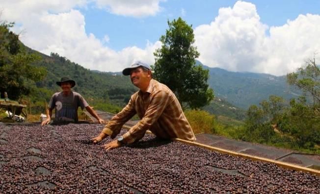
slightly more of a roasted flavour than light. Medium-dark roasts start to bring out
some of the oils of the bean, resulting in slight bittersweet aftertaste. Dark roasted
beans are very oily and result in bitter and smoky flavours.

1.1.4    Grinding

Once roasted, the beans are then ground so that they are ready to be used. Beans
can be ground to different coarseness, which affects flavour extraction in brewing.
If the coffee is under-extracted, not enough flavour will have been extracted (ground
too course). If the ground is too fine then over-extraction can occur, resulting in a
very bitter, unpleasant taste. The perfect coarseness of the grind depends on the
roast of the coffee and the brewing method used.

1.2      Introduction to Brewing Technology

1.2.1    Brewing Methods

With 65% of coffee being drunk at home (2), there is clearly a huge market for the
multiple home brewing technologies that exist.
Instant

One of the most common, and the simplest method of home brewing, is instant
coffee (Figure 1.8 (12)). Water is simply poured on top of the instant coffee granules
and is then ready for consumption. The processing stage of instant coffee creates
soluble granules, allowing the coffee to be drunk without any filtration. However,
creating these granules involves brewing the coffee, followed by a dehydration step,
which detracts flavour from the coffee. Also, cheap beans are used and process
steps are not closely monitored (due to cost), which is why instant coffee is often
considered the worst tasting method of brewing.

                     Figure 1.8 Instant coffee granules ready for brewing

Filter

Another very popular brewing method is drip coffee (Figure 1.9 (13)). This brewing
technique is automated using a machine which heats the water and pours it into a

                                               4
cone shaped filter which contains the coffee granules. The coffee brews in the cone
and slowly drips through into a cup or carafe. This method requires little skill and
can produce many cups of coffee at once.

Pour-over coffee (Figure 1.10 (14)) is effectively a manual take on drip coffee. By
manually pouring the water into the filter, the variables of coffee brewing can be
easily controlled, such as water temperature, water distribution and stirring the
mixture. Correctly controlling these variables can result in a higher quality brew than
using a drip machine.

          Figure 1.9 Drip coffee maker             Figure 1.10 Pour over coffee device

Aeropress

The Aeropress (Figure 1.11 (15)) has a chamber, at the bottom is a paper filter to stop
coffee grinds getting through, and a filter cap to prevent premature dripping. Water
and coffee are immersed in the chamber with a small amount of stirring, before
being pushed through the filter by the pressure of the plunger. The pressure from
the plunger allows more flavour to be extracted from the grinds. The quality of the
method is generally considered to be high, and the technology used is very simple
and portable. However, it can only brew one cup at a time and can be difficult to
push the plunger through the chamber.

              Figure 1.11 Aeropress device          Figure 1.12 French press cafetière

                                             5
French press
French press (Figure 1.12 (16)) is another form of immersion brewing, coffee is
immersed in water inside a cafetière for several minutes. Then, a metal filter is
pushed down through the mixture, filtering the coffee grounds so that the coffee
can be poured out. As pressure isn’t used in extraction, brewing takes longer than
with an Aeropress. This method also has many variables to control, so with practice
a high-quality cup of coffee can be made, and multiple cups at once.
Espresso machine
Espresso machines produce very different coffee to the methods mentioned
previously. These other methods always produce a whole cup of coffee, whereas
espresso machines produce a very small concentrated shot of coffee called an
espresso. The espressos produced can be used to make longer drinks, either by
topping up with water or milk. Espresso machines often have steam wands, which
can heat and froth or foam the milk, used to produce drinks such as lattes, flat whites
or cappuccinos. These machines are generally considered the best way to produce
coffee, for both the quality and the variety of drinks that can be made.
Espresso machines work by forcing pressurised, nearly-boiling water through finely
ground and tightly packed coffee held in a filter, called a portafilter. By extracting
the coffee at such a high pressure, a lot of the flavour of the beans can be extracted
quickly, allowing espresso shots to be made very quickly compared to other brewing
methods. There is a huge variety in ways an espresso machine can work, which vastly
affects the price. They can be automatic, semi-automatic or manual, with a variety
of heating and pressurising mechanisms.
Automatic
Automatic machines are the easiest to use, all they require is for a coffee pod to be
inserted and a button to be pressed, then within a minute a coffee has been made.
However, the ease of use influences both the taste and the environment. The pods
used are made of plastic and a lot of waste is produced this way. Also, due to their
simplicity, the user cannot alter the brewing variables, so they cannot change the
taste of the brew.
Semi-automatic
These machines require coffee grounds to be compressed into the portafilter by a
process called tamping (Figure 1.13 (17)). Using a semi-automatic machine produces
a lot less environmentally damaging waste and can produce better tasting coffee
than automatics, but only if tamped properly for the grind sized used. Therefore,
6semi-automatic machines have a smaller margin for error, especially with new users.
However, with practice the user can produce exactly the type of coffee they want,
as they have complete control over what beans they buy and how fine they grind the
beans.
Figure 1.13 Coffee grinds being tamped in the
portafilter
Manual
Manual machines work in a similar way to semi-automatics. However, to pressurise
the water a lever must be pulled by the user, which is where the term “pulling an
espresso” comes from. This method is extremely difficult to be consistent with and
requires a lot of training.
1.2.2 Espresso Machine Components
Although some machines are very complex and have additional features, all
machines require the same basic mechanisms: heating, driving and filtering. The
complexity of the mechanisms used determines the price of a machine and often its
use, either home or commercial. The range of technology available was evaluated so
that suitable components could be used in the chosen design. The basic schematic
of how a general machine works is shown in Figure 1.14.
Figure 1.14 Espresso machine schematic
7Heating Mechanisms
Boiler
This is a vessel filled with water which is heated using an electrically driven coil inside
the boiler. An electrode is hung from the boiler ceiling to ensure the coil is
submerged, to prevent it burning out. Once the water level descends below the
electrode, more water is pumped in to raise the water level. If no more water can be
pumped in, the coil will switch off (18).
The boiler can reach different temperatures depending on whether brew water or
steam is desired, as only one can be produced at a time (87-93 degrees for brew
water and 125 degrees for steam (19)). As the boiler will be pressurised when
heating, the inlet water needs to be pressured above this pressure.
Heat Exchanger
Alternatively, a heat exchanger is used. Similarly, there is a reservoir of water which
is heated by a heater coil to steam temperatures, but it also contains a heat
exchanger inside of it. Steam generated in the boiler can be used to froth milk at the
same time as pulling a shot. However, as the boiler is used to heat water for both
steam and brew water, changing the boiler temperature will affect both streams,
which usually leads to an unideal temperature in one of them (20).
Mineral deposits can build up in a boiler, this can affect the purity of the water and
therefore taste of the brew. So, the water used for brewing comes from a clean
supply which passes through the heat exchanger and is heated up to temperature,
ensuring the taste of the brew is not affected.
Despite this advantage over a single or double boiler system, adjustments to
temperature in a heat exchanger are less precise, making it harder to fine-tune
flavour. These systems have more components than a single boiler system, making
it more expensive, however they are still cheaper than a double boiler machine.
Double Boiler
The most expensive machines tend to use a two-boiler system; one boiler at brewing
temperature and another at steam temperature (20). This allows both steam and
brewing water to be heated simultaneously and at their ideal temperatures, leading
to higher quality product. Water temperature is more precise than in heat
exchangers, so it is better for commercial scenarios in which accurate temperature
is vital.
8Two-part Thermoblock
Unlike traditional boilers which store water, a thermoblock heats the water upon
demand. It is made up of metal blocks that are mounted together, with a seal
between them (Figure 1.15 (21)). Inside there is a long pathway for the water to travel
through. The block is heated using an embedded heating element, which heats the
water as it travels through, reaching the desired temperature as it exits the thermal
block. This method is a lot cheaper and more compact than using a boiler and has a
lower start-up time to brew. However, as it made from two separate pieces it is
prone to leakage due to seal failure. Also, due to its narrow passages it is prone to
blockages from scale build up, which can result in a lot of maintenance.
Figure 1.15 Inside a two-part thermoblock
Single-part Thermoblock
This thermoblock is essentially stainless-steel piping encased in a block of aluminium
(Figure 1.16 (22)). This has several advantages: being made of a single piece
minimises any risk of leakage, stainless steel is also less susceptible to scale than
aluminium (23) so the chance of blockage is reduced, and the block of aluminium
used is larger so it retains heat better, resulting in more consistent shots.
Figure 1.16 Cut view of a single-part thermoblock
9Drive Mechanisms
Steam-driven
Water is heated in a boiler to produce steam and build up pressure that is used to
push the water through the coffee grinds. This method requires no additional
components to the heating mechanism, so is less expensive. However, it cannot
achieve the pressure needed for a high-quality espresso (24). This method is often
used in lower-cost consumer machines.
Piston-driven
In piston-driven systems a lever is used to pressurise hot water, by the use of a
piston, and push it through the coffee grinds. There are two types of lever used;
manual and spring. Spring lever systems work the same as in manual systems, but
the operator works to tension a spring which then delivers the pressure to the
water, usually producing more consistent results and with less practice needed (25).
Vibratory Pump
Both vibratory and rotary pumps can achieve the 9-15 bar range required for good
espresso and produce it very consistently (26). Vibratory pumps are
electromagnetically driven. They are composed of a piston attached to a magnet,
inside a metal coil.
As electrical current runs through the coil, the electromagnetic effect causes the
piston to move rapidly back and forth, at sixty pushes per second. As the piston
moves back, water fills the pressure chamber. Then, as it moves forward the one-
way ball pushes against the end of the piston, preventing any water flowing back
from where it came. As the piston compresses, water is pressurised and then forced
out the one-way valve and towards the heating mechanism.
Rotary Pump
A rotor is positioned eccentrically in the pump housing. Vanes are slotted into the
rotor, and loaded with springs or hydraulics, to ensure they are always contacting
the housing walls, creating separate chambers. As water enters the pump, the
chambers expand in size, reducing pressure and creating a pressure suction on the
inlet, causing water to flow into the pump. As the rotor continues to rotate, the
chambers get smaller, creating the pressure in the water leaving the pump.
Rotary pumps are significantly quieter in use, more durable and limit the pressure
oscillations in the outlet. However, they are much larger than vibratory pumps, more
expensive, and are considered to have no effect on the taste of the espresso (26).
10Water Delivery Mechanisms
Group head
The group head is the point in the machine at which the water is delivered to the
coffee. It ensures an even spread of water across the coffee grinds using a dispersion
block. This acts like a showerhead, to ensure all the coffee comes into contact with
the water, for full extraction. There are three main types of group head: E61,
saturated and semi-saturated.
The E61 is a classic espresso machine component, being widely used since 1961
(Figure 1.17 (27)). It is a heavy component, made of a large mass of brass. Therefore,
it takes around 15 minutes to heat up to the desired temperature, but then retains
the heat easily, which makes it ideal for producing large amounts of espresso. It is
also entirely mechanical, making it very reliable but also requires more participation
from the user when pulling a shot. It is effectively a mechanically operated three-
way valve: one valve to let the water into the group head, one from the group head
to the portafilter, and one to relieve back pressure from the portafilter.
Figure 1.17 E61 Group head
In saturated group heads (Figure 1.18 (27)), the group head is open to the boiler,
acting as an extension of its so that its saturated with hot water, which allows to it
come to temperature quickly. It also acts as a 3-way valve working in a similar way;
however, it is electronically controlled. Despite heating much quicker, they are often
more expensive and require an expert to perform maintenance work.
11Figure 1.18 La Marzocco GS3 group head
As they are cheaper and easier to maintain, semi-saturated group heads are often
recommended for home espresso machines. They work the same way as saturated
groups, except they have an area directly above the dispersion block which is
separated from the boiler, which does result in marginally less temperature stability.
Portafilter
This is the component which holds the ground coffee, it is comprised of a handle,
for easy handling of the portafilter unit, and a filter basket, where the coffee grounds
are inserted. The filter basket is a removable metal component that fits into the
portafilter exterior. It has lots of small holes in the bottom, which act as a screen for
the coffee grounds, but allow the water with the extracted coffee flavour to pass
through and out into the cup.
Once the ground coffee is inserted into the filter basket, it is then tamped to
compress the grounds. If it is too loosely or too tightly tamped, the result will by sub-
par espresso. Portafilters typically come in either 53mm or 58mm size, either can
make good espresso but the same size tamp needs to be bought to ensure even
compression of coffee grounds. After tamping, the portafilter is locked into the
group head and espresso is ready to be made.
Control Mechanisms
Most modern espresso machines will use some form of control system to regulate
the use of the driving and heating mechanisms, complexity of these systems
depends on the price of the machine. Lower-end machines use a very simple system
for controlling the heating. They have a thermostat at some point in the machine,
often the boiler. Once the temperature of the water reaches above a certain point,
the heating element turns off. When the water then drops below a certain
temperature, the heating element turns back on (28). Although this is very simple
and cheap to implement, it results in a highly fluctuating temperature of water for
brewing. At best this leads to inconsistent taste in espresso but can cause poor taste
at certain temperatures.
12More expensive units use more complex control, achieved by the use of
microcontroller (MCU) or microprocessor (MPU) based development boards. A
development board is essentially a very small and simple computer, they are
programmable and come in varying complexities. In an espresso machine they are
usually used for Proportional Integral Derivative (PID) control. PID controllers
attempt to predict what is going to happen and act accordingly to keep the system
under control. In this case, the development board keeps the water temperature
under control before it goes askew. This is done by programming an algorithm into
the board. There are a huge number of development boards available, and different
boards are suited to different uses.
Development Boards
Computer Chip
The biggest differentiation between boards is whether they are run using an MCU
or MPU, both of which are just types of computer chip. An MCU is slower, more
integrated, easier to program, easier to design, requires no operating system,
consumes less power, and is generally cheaper than an MPU. On the other hand, an
MPU is faster, has more memory, but usually more complex to program. However,
this does mean MPUs can carry out more complex tasks than MCUs (29).
Voltage
The voltage is also a huge consideration when selecting a development board, their
specifications will state both the input voltage and operating voltage. Input voltage is
that provided to the board via an external power source (varying from 7-20V
depending on the board). Operating voltage is the voltage the board supplies for
externally connected devices (generally either 3.3 or 5V). Any externally connected
devices that operate with a different voltage to the operational voltage will require
a voltage divider or bidirectional level shifter. This is needed to ensure the devices
can operate without any damage to them.
Current
Boards also have a DC current per I/O pin on their specification, this refers to how
much current is available to externally connected electrical components. If the
component connected requires a different current to operate then the supplied
current may need to be regulated before connecting the pins.
13Clock-speed
This is the processing speed of the board. High clock-speeds are used for highly
complex and time-critical functions. However, high clock-speeds use comparatively
more power.
GPIO
General Purpose Input/Output pins (GPIO) allow for the board to communicate with
external components. GPIO pins can be categorised into analog and digital.
Digital pins are seen as either HIGH, above 66% of the operating voltage, or LOW,
anything below 66%. However, sometimes more than just HIGH or LOW signalling is
needed. For example, varying the amount of heat exerted by a heating element.
These applications use Pulse-Width Modulation (PWM) digital pins. They allow
toggling between HIGH and LOW at programmable ratios. This allows the average
voltage to be controlled, similar to an analog output.
Analog pins are capable of reading analog voltage signals (using an Analog-to-Digital
Converter) and output true analog voltage (using a Digital-to-Analog Converter).
This is useful in scenarios where you need to measure a voltage, rather than just a
HIGH or LOW logic state.
Size
Boards can come in all different sizes. If the project has size constraints, then only
certain boards can be used.
Software
Each board will support certain coding languages, from low-level to high-level. Low-
level languages, such as C, are closer to how computers “talk” and run directly on
the processor, they are more difficult to learn but use less storage and can be highly
powerful. High-level languages, such as Python, are closer to how humans “talk”, and
take less time to program, but perform poorer (30). Some boards will support a
variety of coding languages.
Available Technologies
As there are too many development boards to list, only the most popular boards
were evaluated. The advantage of using a popular board is that there is a larger
online community to support any issues that arise. Also, there is a greater chance of
finding a base code for any activities, which can then be edited to tailor to the
situation, saving a lot of time in comparison to writing code from scratch.
14Arduino Uno
The Arduino family of boards are microcontroller-based and are an open source
design, therefore do not have an operating system and run purely off written code.
However, they communicate very easily with a wide range of electronic components,
such as sensors and motors and are very power conservative. Also, there is many
add-ons – shields - that can be installed to increases the uses of the Arduino, such
as a Wi-Fi connectivity, touchscreen, cameras and microphone capabilities.
Arduino Micro & Mega
Although the Uno is the most popular Arduino, there are others available for slightly
different uses. If size of board is a restriction, the Micro is an alternative to the Uno.
as it is 3x smaller, with the same processing power, memory and even more GPIO
pins. However, it does not have the capability to use shields, restricting its uses.
If the project requires a large amount of code, lots of GPIO pins, and size is not a
restriction, then the Mega is an excellent choice. It has 8x more memory space than
the others and 4x more SRAM, allowing it to create and manipulate more variables
when it runs. It is also compatible with shields, but it the most expensive of the three
Arduino boards.
Raspberry Pi 3
The Raspberry PI is in fact an entire computer with its own operating system, giving
it a huge range of functionality and can handle more complex tasks. It can do
everything that an Arduino can, however interacting with hardware components is
more complicated on the Pi. When dealing with software, the Pi excels and already
has Wi-Fi, HDMI and Bluetooth capabilities built-in.
BeagleBone
This board is very similar to the Raspberry Pi, offering all the same benefits but with
a more powerful processor, more GPIO pins and onboard storage (no SD card
required), making it perfect for very complex tasks, such as face detection. However,
these improvements come with a cost, and thus the BeagleBone is more expensive
than the Raspberry Pi. Similarly to the Arduino, the BeagleBone is open source.
The attributes of the listed technologies were compared in Table 1.1.
15Development Arduino Uno Arduino Micro Arduino Mega Raspberry BeagleBone
Board Pi 3
Price £20 £18 £35 £35 £50
Dimensions 69mm x 48mm x 18mm 102mm x 85mm x 86mm x
53mm 53mm 56mm 53mm
Processor Atmega328P Atmega2560 Atmega32U4 Quad Core ARM Cortex-
ARM A8
Cortex-A53
Clock Speed 16MHz 16MHz 16MHz 1.2GHz 1GHz
Flash Memory 32kB 32kB 256kB microSD 2GB
SRAM 2kB 2.5kB 8kB 1GB 512MB
Voltage (V) 5 5 5
Digital I/O Pins 14 54 20 40 46
Digital I/O Pins 6 15 7 2 5
with PWM
Analog Pins 6 16 12 0 7
Ethernet/Wi- No (A shield No No (A shield Yes Yes
Fi/Bluetooth can enable it) can enable it)
Table 1.1 Control board attributes
1.3 Introduction to the Maker Community
By definition, a maker is simply someone who creates, or forms, something. More
commonly it is linked to someone involved in the maker movement. It is changing the
way people think about education, technology and more (31). It is harbouring the
collaboration of people, helping them to realise that more can be achieved together
than alone.
The maker community is made up of people that share their successes and failures,
allowing others to learn, develop their skills and build upon others work. A maker in
the community is someone who builds their own, or improves an existing, product.
Makers often use makerspaces (also known as hackspaces), which are shared
workshops which contain various tools and manufacturing equipment to be used.
161.3.1 History
The maker movement has developed from the wider do it yourself (DIY) movement.
This is a movement that can be traced back to centuries ago, where a collection of
Greek buildings were found to have been built almost identically using instructions
inscribed on parts of the building (32).
More recently, there was a surge in population of DIY in the 60s and 70s in the UK.
One of the reasons for this surge was economic difficulties for many at this time.
Making your own, or repairing, items such as clothing, furniture and electronics
became a way to help deal with the struggle for economic stability for many people.
However, as the global economy improved during the 90s and 2000s, popularity of
DIY took a dip, as those who were doing it purely for economic reasons no longer
needed to (33). During this time, the internet advanced dramatically and became
much more widespread, making the sharing of information accessible to almost
anyone. Websites such as Wikipedia have enabled people to educate themselves on
a vast range of topics, encouraging them to have a more proactive mindset. Also,
sites such as Instructibles and Youtube, which provide millions of user-submitted
tutorials, have made it so easy for people to get involved with DIY.
In 2008 there was another economic crash, leaving people looking for ways to save
money, and once again finding DIY. This, along with the development of maker-
friendly manufacturing methods (3D printing), and the ease and accessibility to DIY
information from the internet, has led to huge growth in the DIY movement,
particularly in the subculture of the maker movement.
1.3.2 Current State
With the increased popularity of the maker movement in the last 10 years, there has
been several websites and magazines supporting this culture. For example, Maker
Media publish magazines and books every year, have a large presence on youtube,
sell products online and even host Maker Fairs. These faires celebrate the “DIY
mindset” through people’s projects and creations, bringing in over a million visitors
a year. Their Youtube channel now has over 1.5 million subscribers, and they even
created their own site, MakerSpace, created to allow people to share their projects
with others.
There are many websites similar to MakerSpace, allowing people to interact with
the maker community. Thingiverse, owned by MakerBot (a 3D printer company), is
primarily 3D printed projects only. Hackaday is one of the largest collaborative
hardware development communities, which isn’t restricted to just 3D printed
17projects. Most projects here involve the use of development boards, often to “hack”
existing products to improve them, but also to create products from scratch. The
website also runs contests with prizes, increasing the activity within the community.
Another website, Instructibles, was bought by AutoDesk in 2011 for $32 million,
highlighting the value of this growing community. Instructables allows users to share
any type of DIY projects, it also has a list of classes available to help makers learn
new techniques, such as 3D printing, electronics, crafts and even food courses. In
addition to just sharing their projects, all these sites allow users to upload their files
and build instructions in an open source format, so anyone else can re-create the
project they have developed.
1.3.3 Open Source
The term “open source” refers to something people can use, modify and share
because it is publicly accessible. This originated in reference to software
development, where users could access freely available source code. For example,
this is the basis on which Linux is built. By freely sharing the source code, it allows
users to modify for their own personal gain but often these modifications are shared
with the community. This results in quicker and better development of software
than would not be achievable with a small, closed group of people, leading to shorter
time-to-market.
Today, however, “open source” has branched out to involve hardware projects too,
such as Arduino, who sell their products but also share their blueprints online.
Whilst sharing an open source software design only requires source code, hardware
designs require a lot more information to be considered truly “open source” and can
change from design-to-design. Generally, it will include: instructions for
manufacture, bill of materials, digital files for manufacture (CNC routers, 3D
printing, Laser cutting), technical drawings, electronic schematics, along with any
source code if programming is required.
Open source is often used to democratise designs, taking existing products and
creating open source variations on them, making them customisable to different
needs and therefore accessible to a larger group of people. Along with accessibility,
the community-based approach of open source ensures greater reliability and
security, as there are more people thoroughly reviewing and vetting designs.
To prevent others stealing, privatising and monetizing open source designs, licenses
are used to outline the terms of use. There are a variety of software licenses
available, as per The Open Source Initiative (34), which slightly differ from each
other, but generally cover the same points:
18• The source code is available to, and may be distributed freely to anyone
• If any changes are made to the source code it must be released as a new
version with a unique version number
• The above two points hold true as long as the copyrights and disclaimers of
warranty of the licence are maintained
Hardware projects are also covered by licences such as the CERN Open Hardware
Licence (CERN OHL), which protects design documentation in the same way
software licences protect source code. Design documentation is defined in this
licence as “schematic diagrams, designs, circuit or circuit board layouts, mechanical
drawings, flow charts and descriptive text, and other explanatory material that is
explicitly stated as being made available under the conditions of this Licence.” (CERN
Open Hardware License V1.2) It also states that any code, software or firmware used
in programmable devices in the design must be explicitly expressed to be subject to
the licence, otherwise it will be subject to the applicable licence terms and
conditions.
1.4 Previous work
Research was conducted to find existing DIY coffee machine and open source
projects. The most common form of project found was “hacking” existing espresso
machines by installing PID controllers (35). There is many of these projects which
share enough detail to be considered open source. However, these projects are
model specific and have only been carried out on boiler systems, which limits their
use and means there is many espresso machine models without an open source PID
controller available.
There are more “hacking” projects which implement an additional control board
(sometimes multiple) to an existing machine (36) for a variety of functions such as:
Wi-Fi connectivity, mobile/laptop application control, voice control, along with many
more. Although there is a lot of “hacking” projects, they all require modifying an
existing machine. There are much fewer entire coffee machine open source projects
and are all for either drip or pour-over machines (37).
1.5 Conclusion
Coffee is grown, harvested, and processed in such a number of ways that using
constant brewing parameters will not produce “good” tasting coffee for every
variety of coffee grounds. Therefore, a successful coffee machine design will have
scope for altering brewing parameters.
19There is a wide range of brewing technologies, each have their own advantages,
disadvantages and intricacies. However, none of the other technologies have the
same complexity or variety of components as the espresso machine, which makes it
the appropriate technology to pursue for a final year project. One of the main
differences between low-end and high-end machines is their temperature accuracy
and stability. Thus, a primary focus of the design was to use low-end components
and improve these attributes, effectively increasing the value of the machine.
Another focus was to create a novel design. The coffee industry is huge, worth
billions of dollars and has been around for a long time, meaning a vast quantity of
designs have been explored already and it would have been difficult to compete
without the financial backing that other companies have. Conversely, the open
source community is relatively new and as research has shown, there was no “fully”
open source espresso machines available, which provided a lot of freedom for a
novel design. An open source approach meant becoming part of the “open source
community”, which provided support for obtaining information or accessing help,
and offered an opportunity for the project to continue beyond given timescale.
2 DESIGN PROCESS
2.1 Aims & Objectives
2.1.1 Aims
The main aim of this project was to design and build an open source espresso
machine, whilst providing enough documentation so that anyone could build it in a
typical makerspace using publicly available components. Another aim was to replace
components for more standardised and widely available components.
2.1.2 Objectives
• Use research to influence the selection of an existing machine to purchase
• Carry out primary research of the advantages and disadvantages of existing
products
• Test the performance of the machine, providing a benchmark for comparison
with prototypes created
• Reverse engineer the existing machine to obtain further understanding of
how the technology works
• Utilise existing components to a simple Arduino controlled first prototype
20• Make a second prototype which is comprised of the same components, but
in a casing which resembles that of a coffee machine
• Identify components which are not widely available and replace them with
standardised, readily available components
• Outline direction for further work to aid the continuation of the project by
the wider open source community.
2.2 Methodology
Once research had been completed, it was decided to take the approach of reverse
engineering an existing consumer machine. This helps to develop a deeper
understanding of what is desirable in an espresso machine design and how they
work, which influenced the design specification. It also provided the opportunity to
measure the performance of a consumer product, allowing for comparison with any
designs produced.
The design was chosen to be developed by using a series of prototypes, rather than
producing the final design at first attempt. This helped to incorporate a “learning by
doing approach”, which is often carried out in the maker community (38), and
helped to debug any issues that arose.
Following the values of many open source projects, the progress of the project was
shared on Hackaday to interact with the open source community. It was expected
that this interaction would provide assistance and support to the project.
2.3 Design Selection
The main components that required design selection were the pump, heater and
control board. As these components are drastically different, their selection criteria
also differed. The weighted objectives method (39) was used to aid selection.
The relevant objectives for the heater, pump and control board all differ from each
other. Thus, a criterion-weighting matrix was created for each of the component
types.
21Heater
The technologies evaluated for the heating mechanism were those identified in
Section 1.2.2.
Price Start- Temperature Maintenance Steaming Total Weighting
up time stability ability
Price X 1 1 1 1 4 5
Start-up time 0 X 0 1 1 2 3
Temperature 0 1 X 1 1 3 4
stability
Maintenance 0 0 0 X 1 1 2
Steaming 0 0 0 0 X 0 1
ability
Table 2.1 Heater weighting matrix
Price Start-up Temperature Maintenance Steaming Weighted
time stability ability total
Boiler 3 1 4 2 3 41
Double 1 1 4 2 5 33
Boiler
Heat 2 1 2 3 5 32
Exchanger
Thermoblock 4 5 3 2 2 53
(two-part)
Thermoblock 3 5 3 4 2 52
(single-part)
Table 2.2 Heater decision matrix
Clearly, it would be ideal to use either type of thermoblock due to their low price,
quick start up time (approximately half a minute compared to several minutes in
boiler systems) and reasonable temperature stability, which could be improved by
implementing temperature control methods.
22Drive mechanism
The same method was used to select the technology used for the drive mechanism,
which were outlined in Section 1.2.2.
Achievable pressure Consistency Noise Price Total Weighting
Achievable X 1 1 1 3 4
pressure
Consistency 0 X 1 0 1 2
Noise 0 0 X 0 0 1
Price 0 1 1 X 2 3
Table 2.3 Pump weighting matrix
Achievable Consistency Noise Price Weighted
pressure Total
Steam driven 1 4 4 5 31
Piston driven 5 1 5 3 36
Vibratory pump 5 4 1 4 41
Rotary pump 5 5 3 2 39
Table 2.4 Pump decision matrix
Even though the rotary pump scored so closely to the vibratory pump, there is no
evidence of improved taste of espresso with a rotary pump. Therefore, the vibratory
pump was chosen due to its significantly lower cost.
Control board
The most important criteria were selected from the more extensive list of attributes
seen in Section 1.2.2.
Price Size No. of Shield Processing Total Weighting
suitable pins capability power
Price X 1 0 0 1 2 3
Size 0 X 0 0 1 1 2
No. of 1 1 X 1 1 4 5
suitable pins
Shield 1 1 0 X 1 3 4
capability
Processing 0 0 0 0 X 0 1
power
Table 2.5 Control board weighting matrix
23Price Size No. of Shield Processing Weighted
suitable pins capability power total
Arduino Uno 5 3 2 5 1 52
Arduino 5 5 4 1 1 50
Micro
Arduino 3 2 2 5 1 44
Mega
Raspberry Pi 3 3 1 5 5 45
BeagleBone 1 3 3 5 5 49
Table 2.6 Control board decision matrix
As the processes the control board will be carrying out will be very simple tasks (at
least so in the first few iterations of the project), not much processing power will be
required. Due to their lower cost, power consumption and large online community,
the Arduino Uno and Micro are the more favourable options. Both have a good range
of digital, PWM and analogue pins which will be required for the design. Despite the
Micro costing less and being smaller, the ability of the Uno to support shields makes
it the chosen model for the project, as this allows features such as interaction with
sensors or Wi-Fi capabilities much easier, and size is not of huge concern to begin
with. The Arduino Uno is also an open source design, which fits very well into the
ethos of the project.
2.4 Reverse Engineering
It was decided to purchase an espresso machine and reverse engineer it. This
involved using the machine to gain first-hand experience of the pros and cons of a
consumer machine, which helped to influence the open source machine design. The
machine’s temperature stability was then measured, before dismantling it to obtain
a greater understanding of its workings. The components were then re-used,
provided they could either be manufactured otherwise or were openly available to
buy.
Machine selection was influenced by several factors, mainly components desired
from the design selection (Section 2.3), reviews, and budget (£150). The De’longhi
Dedica Style EC865.M satisfied all the criteria, and thus was chosen (Figure 2.1).
24Figure 2.1 De’Longhi Dedica Style EC685.M
2.4.1 User Experience
From use of the machine, the following pros and cons were identified:
Pros
• Removable water tank
• Quick start-up time was very convenient
• Option for single or double espresso
• Does not run if there is no water in the tank
Cons
• No indication of low water level
• Temperature intervals are not quantitative – low, medium and high
• User interface is complicated due to a lack of a screen
• Very difficult to disassemble
• Requires running hot water through the machine to achieve good tasting
espresso, but lacks a pre-heat function
From personal use of this machine, it was found that running several cycles of hot
water through the machine before pulling a shot drastically improved the taste of
the espresso. Therefore, an investigation was designed to measure the variation of
water temperature from cycle-to-cycle. Also, it was suspected, from the price of the
machine, that it had a cheap and simple control system for regulating water
25temperature throughout the cycle. Thus, water temperature variation throughout a
single cycle was also a variable of interest to be measured.
2.4.2 Experimentation
A temperature probe was inserted to a tee fitting and placed between the heater
and group head (Figure 2.2), testing under various scenarios. In all cases the machine
was run without any coffee or the portafilter in. As there were a lot of tests to be
ran, this would have made experimentation slow and expensive if coffee was used.
Firstly, the machine was run from cold, allowing approximately 30s between cycles
(roughly the time to change the portafilter), running double shots each time. Next,
the machine was run with each cycle back-to-back, from cold, running the next cycle
as soon as possible. Then, once again cycles were ran with 30s between each, but
after preheating the machine with two back-to-back cycles.
Figure 2.2 Thermocouple inserted into a tee fitting
Experiment one
The first experiment (Figure 2.3) shows that temperature varies from cycle-to-cycle
- ±2°C. But, it also shows that when heated from cold the temperature peaks at
approximately 75°C, which is lower than desired. It is clear that temperature during
the cycle changes drastically, with a large portion of the cycle at low temperature,
which will result in poor tasting coffee. Red lines indicate the pre-infusion pumping
stage, green indicate the main pumping cycle.
26Figure 2.3 Experiment one
Experiment two
This experiment (Figure 2.4) demonstrates that when running multiple cycles
through the machine to effectively “Pre-heat”, higher peak temperatures can be
achieved, a lot closer to the desired range of 87-93°C, with a larger portion of the
cycle occurring at desirable temperatures
Figure 2.4 Experiment two
27Experiment three
The final experiment further investigated the effect of using “pre-heat” cycles, but
emulates actual machine use more realistically, by allowing a 30 second break
(similar to the time taken to tamp and insert a portafilter) between the brew cycle
and “pre-heat” cycles. As shown in Figure 2.5, this proves the “pre-heat” cycles are
an effective method to ensure the majority of the cycle occurs in an acceptable
temperature range.
Figure 2.5 Experiment three
In all the cycles, the temperature curves are composed of one rise and one fall,
suggesting that the heater simply turns on once and then turns off, making it difficult
to achieve a flat temperature curve. From this, it was concluded that not only should
the open source design include a pre-heat function to reduce cycle variation at start-
up, but it should also attempt to achieve greater temperature stability during each
cycle.
2.4.3 Dismantling
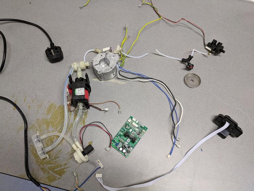
Once the existing machine had been tested, it was dismantled (Figure 2.6). This
helped to reaffirm the understanding how the technology works by providing visual
aid. It also helped to learn how the components were connected electronically,
which influenced the electronics used in the first prototype.
28Figure 2.6 Components from the dismantled machine
Research was then carried out on all the components, evaluating their public
availability for purchase. Generally, widely available components were not used in
the existing machine. However, all components were publicly available, apart from
some of the group head design, which was integrated into the casing.
2.5 Design Specification
A design specification was written to identify the boundaries which the design must
comply with to be considered successful. The specification took into account both
the performance of the machine and the ability for it to be manufactured in a maker
space.
Performance
• The machine should be able to produce both single (25-30ml using 7g dried
coffee) and double (50-60ml using 14g dried coffee) shots
• The machine should produce a water pressure of at least 9 bar when the
water contacts the coffee
• The machine should heat the water to 87-95 °C when it contacts the coffee
• The machine should pump water briefly in a pre-infusion stage before the
main pumping stage
• Water tank should be able to hold at least 1 litre
29Environment
• Internal piping components must be rated to withstand up to 125°C
• Internal piping components must be rated to withstand up to 15 bar
Maintenance
• The design should allow for ease of dismantling and replacement of parts
Target cost
• Total cost of materials and components should not exceed £300
Manufacturing
• The machine must be able to be manufactured in a typical maker space, using
machines such as those mentioned in Section 2.5.1
Size
• The total size of the machine should be reasonable for a home espresso
machine, not exceeding 0.4m x 0.4m x 0.4m
Materials and Components
• All materials and components should be readily available to be purchased
• As many components as possible should be able to be manufactured by the
user
Safety
• The machine must pass PAT testing
• The machine must be safe to operate under standard usage
• Build instructions must include relevant safety warnings
Documentation
• All information required to build the machine should be made readily
available to the open source community
Disposal
• The machine should be designed for safe dismantling to allow individual
components to be reused, recycled or disposed of
2.5.1 Manufacturing Facilities
For the machine to be manufactured in a maker space, first the tools available in a
maker space must be defined. The tools in each space will vary slightly from location
30You can also read