Human body movements performed by machines - FREDRIK KUYLENSTIERNA DEPARTMENT OF INDUSTRIAL AND MATERIALS SCIENCE - Chalmers ...
←
→
Page content transcription
If your browser does not render page correctly, please read the page content below
Human body movements performed by
machines
Master’s thesis in Product Development

FREDRIK KUYLENSTIERNA

DEPARTMENT OF INDUSTRIAL AND MATERIALS SCIENCE
C HALMERS U NIVERSITY     OF   T ECHNOLOGY
Gothenburg, Sweden 2021
www.chalmers.se
Master’s thesis 2021

  A master’s thesis that aims to record and
mechanically reproduce human body movement

            FREDRIK KUYLENSTIERNA

        Department of Industrial and Materials Science
         Chalmers University of Technology
                 Gothenburg, Sweden 2021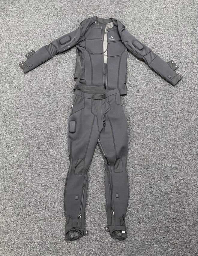
A master’s thesis that aims to record and mechanically reproduce human body
movement
FREDRIK KUYLENSTIERNA

© FREDRIK KUYLENSTIERNA, 2021.

Supervisor: Hanna Börjesson, Volvo Cars
Examiner: Asst. Prof. Karinne Ramirez-Amaro, Department of Electrical Engi-
neering

Master’s Thesis 2021
Department of Industrial and Materials Science
Chalmers University of Technology
SE-412 96 Gothenburg
Telephone +46 31 772 1000

Cover: The developed final prototype of the project performing a kick under the
bumper of a Volvo XC60.

Typeset in LATEX
Gothenburg, Sweden 2021

iv
A master’s thesis that aims to record and mechanically reproduce human body
movement
Fredrik Kuylenstierna
Department of Industrial and Materials Science
Chalmers University of Technology

Abstract
Recent customer feedback received by Volvo Cars shows that the function to open
the tailgate without using any hands is among the top functions on the vehicle sub-
ject to user complaints. The current test and calibration methods of the function
involves repetitive kicking by a human to open and close the tailgate. The aim of
this project was to analyze a human kicking motion and recreate the same motion
with a robot, which in turn should activate the opening and closing of the tailgate.
By replacing the human kicker with a robot, unwanted variation of the kicking mo-
tions in the calibration and test processes is eliminated.

A method to record human kicks with an optical motion sensor tracking technol-
ogy has been developed. The motion tracking uses a VR environment in the Unity
software as a platform to generate Cartesian data from the movement. The gener-
ated motion data is imported to the software RobotStudio to enable offline robot
programming. A trajectory is created in RobotStudio, based on the input file of the
recorded human motion data. The trajectory is then performed by a real robot of
the model IRB1200 from the manufacturer ABB Robotics. The robot was outfitted
to resemble a real leg by attaching a shoe and jeans material.

The functionality of the solution was verified with a Volvo XC60 through quantita-
tive testing. The testing confirms that the robot can successfully repeat identical
kicks to open and close the tailgate. Future work for Volvo Cars includes developing
new test programs that utilize the solution.

Keywords: Human motion tracking, Robot movement, Virtual reality applications,
Robot trajectory planning, Human leg replication

                                                                                  v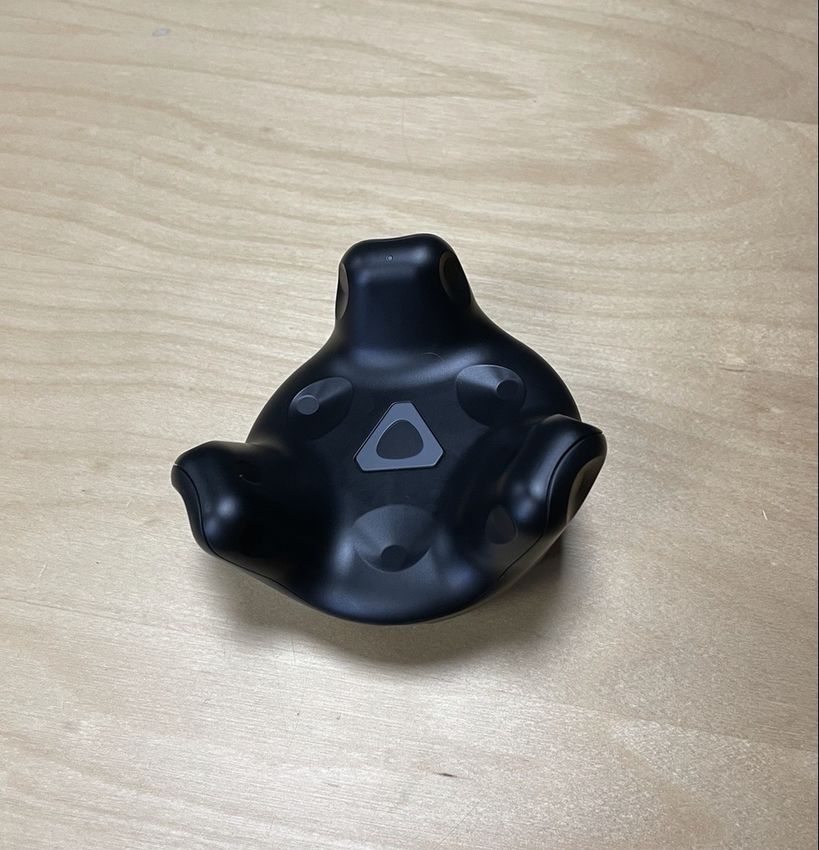
Acknowledgements
First and foremost, I would like to express my gratitude for my project partner Joël
Brou Boni. We had a great collaboration throughout this project and performed all
practical development activities as joint efforts.

I would like to thank the department of Door Control, Locking & Alarm at Volvo
Cars for the opportunity to write this master’s thesis. In this department, I would
like to express a special thanks to my supervisor Hanna Börjesson for your super-
vision, support and help throughout the project. I would also like to thank the
department Open Innovation Arena at Volvo Cars for the support during the devel-
opment of the motion tracking solution. A special thanks to Timotei Florin Ghiurau,
Aljoscha Ledwa and Romit Godi working in this department. I would also like to
thank the persons supporting the project from ABB Robotics. This includes Göran
Manske, Patrik Nilsson, Viktoria Lundstöm, Anders Spaak and Göran Bergström
who provided the project with a robot and supported the creation of the final pro-
totype. Finally I would like to thank my examiner Karinne Ramirez-Amaro for
the support during the development process and for helping me succeed with the
project.

                                    Fredrik Kuylenstierna, Gothenburg, June 2021

                                                                                 vii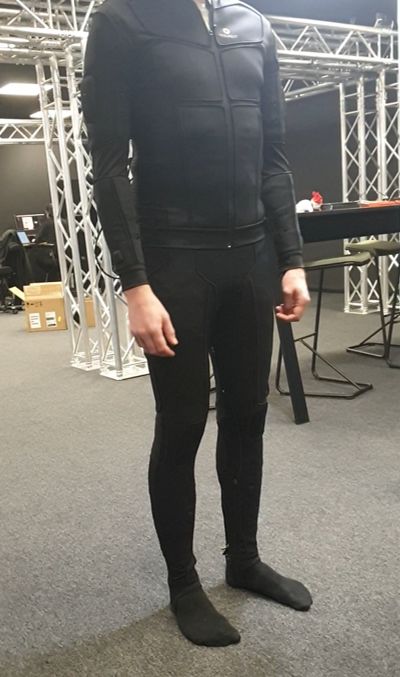
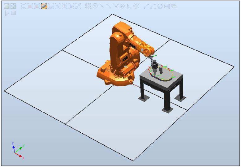
Table of Contents

1 Introduction                                                                                                              1
  1.1 Background . . . . . . . . . . . .    .   .   .   .   .   .   .   .   .   .   .   .   .   .   .   .   .   .   .   .   1
  1.2 Related work . . . . . . . . . . .    .   .   .   .   .   .   .   .   .   .   .   .   .   .   .   .   .   .   .   .   2
       1.2.1 Motion tracking . . . . . .    .   .   .   .   .   .   .   .   .   .   .   .   .   .   .   .   .   .   .   .   2
       1.2.2 Robot movement . . . . .       .   .   .   .   .   .   .   .   .   .   .   .   .   .   .   .   .   .   .   .   3
  1.3 Aim . . . . . . . . . . . . . . . .   .   .   .   .   .   .   .   .   .   .   .   .   .   .   .   .   .   .   .   .   4
  1.4 Problem definition . . . . . . . .    .   .   .   .   .   .   .   .   .   .   .   .   .   .   .   .   .   .   .   .   4
  1.5 Research approach . . . . . . . .     .   .   .   .   .   .   .   .   .   .   .   .   .   .   .   .   .   .   .   .   4
  1.6 Foot Movement Detection Module        .   .   .   .   .   .   .   .   .   .   .   .   .   .   .   .   .   .   .   .   5
  1.7 Demarcations . . . . . . . . . . .    .   .   .   .   .   .   .   .   .   .   .   .   .   .   .   .   .   .   .   .   6
  1.8 Additional aspects of the project     .   .   .   .   .   .   .   .   .   .   .   .   .   .   .   .   .   .   .   .   7
       1.8.1 Social aspects . . . . . . .   .   .   .   .   .   .   .   .   .   .   .   .   .   .   .   .   .   .   .   .   7
       1.8.2 Ecological aspects . . . . .   .   .   .   .   .   .   .   .   .   .   .   .   .   .   .   .   .   .   .   .   7

2 Technical Background                                                           9
  2.1 Fundamentals of imitation . . . . . . . . . . . . . . . . . . . . . . . . 9
  2.2 From motion recognition to reproduction . . . . . . . . . . . . . . . . 9
  2.3 Computer aided design . . . . . . . . . . . . . . . . . . . . . . . . . . 11

3 Method                                                                                                                    12
  3.1 Current solutions . . . . . . . . . . . . . . . . . . . . . . . . . . . . .                                           13
      3.1.1 Motion tracking . . . . . . . . . . . . . . . . . . . . . . . . . .                                             13
               3.1.1.1 Tracking techniques . . . . . . . . . . . . . . . . . .                                              13
               3.1.1.2 Motion tracking in virtual reality . . . . . . . . . . .                                             16
               3.1.1.3 Available products for motion tracking in virtual reality                                            16
      3.1.2 Virtual reality platforms . . . . . . . . . . . . . . . . . . . . .                                             17
      3.1.3 Robotics . . . . . . . . . . . . . . . . . . . . . . . . . . . . . .                                            18
               3.1.3.1 Robot configuration . . . . . . . . . . . . . . . . . .                                              18
               3.1.3.2 Robot programming . . . . . . . . . . . . . . . . . .                                                19
               3.1.3.3 Robot types . . . . . . . . . . . . . . . . . . . . . . .                                            20
  3.2 Requirements list . . . . . . . . . . . . . . . . . . . . . . . . . . . . .                                           20
  3.3 Procurement of motion tracking equipment and robot . . . . . . . . .                                                  22
      3.3.1 Motion tracking equipment . . . . . . . . . . . . . . . . . . . .                                               22
      3.3.2 Robot . . . . . . . . . . . . . . . . . . . . . . . . . . . . . . .                                             23
  3.4 Initial testing of chosen solutions . . . . . . . . . . . . . . . . . . . .                                           25
      3.4.1 Human motion tracking . . . . . . . . . . . . . . . . . . . . .                                                 25

                                                                                                                            ix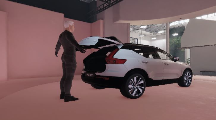
Table of Contents

          3.4.2 Mechanical movement . . . . . . . . . . . . . . . . . . . . . .                                      29
    3.5   Adaptation of solution for motion tracking related to concept limitations                                  31
    3.6   Detailed prototype design and construction . . . . . . . . . . . . . . .                                   33
          3.6.1 Human motion tracking . . . . . . . . . . . . . . . . . . . . .                                      33
          3.6.2 Mechanical movement . . . . . . . . . . . . . . . . . . . . . .                                      34
                  3.6.2.1 CATIA V5 . . . . . . . . . . . . . . . . . . . . . . .                                     34
                  3.6.2.2 RobotStudio add-in . . . . . . . . . . . . . . . . . .                                     35
                  3.6.2.3 Robot appearance . . . . . . . . . . . . . . . . . . .                                     35
    3.7   Verification of solution . . . . . . . . . . . . . . . . . . . . . . . . . .                               37

4 Results                                                                                                            40
  4.1 Initial testing of chosen techniques . . . .       .   .   .   .   .   .   .   .   .   .   .   .   .   .   .   40
      4.1.1 Human motion tracking . . . . . .            .   .   .   .   .   .   .   .   .   .   .   .   .   .   .   40
      4.1.2 Mechanical movement . . . . . . .            .   .   .   .   .   .   .   .   .   .   .   .   .   .   .   41
  4.2 Detailed prototype design and construction         .   .   .   .   .   .   .   .   .   .   .   .   .   .   .   42
      4.2.1 Motion tracking . . . . . . . . . . .        .   .   .   .   .   .   .   .   .   .   .   .   .   .   .   42
      4.2.2 Mechanical movement . . . . . . .            .   .   .   .   .   .   .   .   .   .   .   .   .   .   .   44
  4.3 Verification of solution . . . . . . . . . . .     .   .   .   .   .   .   .   .   .   .   .   .   .   .   .   45

5 Discussion                                                                      46
  5.1 Fulfillment of requirements list for final prototype . . . . . . . . . . . 46
  5.2 Design of final prototype . . . . . . . . . . . . . . . . . . . . . . . . . 47
  5.3 Involving ABB Robotics . . . . . . . . . . . . . . . . . . . . . . . . . 48

6 Conclusion                                                                                                         49

7 Recommendations                                                                                                    50

Bibliography                                                                                                         52

A Robot specification                                                                                                 I

B C# Scripts                                                                    II
  B.1 Motion tracking Teslasuit . . . . . . . . . . . . . . . . . . . . . . . . II
  B.2 Motion tracking HTC Vive Tracker . . . . . . . . . . . . . . . . . . . V

C Python Scripts                                                                 IX
  C.1 Notebook in Google Colaboratory during initial testing . . . . . . . . IX
  C.2 Notebook in Google Colaboratory during detailed prototype design
      and construction . . . . . . . . . . . . . . . . . . . . . . . . . . . . . XIII

D RobotStudio programs                                                      XVII
  D.1 Generated code from manually created robtargets . . . . . . . . . . . XVIII
  D.2 Generated code from add-in used for verification testing . . . . . . . . XIX

E Sketch of profile used to create a geometry in CATIA V5                                                    XXVI

F Data file with coordinates used for verification testing                                               XXVII

x
1
Introduction
The modern automotive industry is transitioning into a new era. The car ownership
in 2021 is no longer just about transportation. The focus has shifted towards com-
munication, connectivity and convenience and the user is at the center of it. Car
manufacturers all over the world spend a lot of time, money and effort on coming up
with new concepts and functions with the intention of elevating the user experience.
A function that achieves this is one where the user can perform touchless opening
and closing of the tailgate on the vehicle. This allows for access to the trunk with-
out using any hands. One situations where this is useful is when returning from
the grocery store with one bag in each hand. The touchless opening allows the user
to load the bags into the car without ever placing the groceries on the ground. A
second scenario when the function is helpful is when the tailgate is dirty and the user
can perform the opening without having to worry for becoming dirty. One common
way to activate the function is by performing a kicking motion underneath the rear
bumper. This feature is used by many car manufacturers for models identified in
the premium segment. Volvo Cars is a company acting in the premium segment
and includes the touchless opening as an option for most vehicle models [1]. How-
ever, the feature is known for receiving user complaints from a range of different car
manufacturers. This master’s thesis was a proposal from Volvo Cars to generate a
tool that will enable better testing methods of the unit performing the opening and
closing of the tailgate and thus support its future development.
1.1 Background
Recent customer feedback received by Volvo Cars shows that the function to open
the tailgate without using any hands is in need of modifications and upgrades. It is
among the top functions subject to customer complaints [2]. There are two promi-
nent complaints about the function. The first one being that there is no clear
indication on the car where to perform the kick to open the tailgate. As there is no
indication, many users perform the kick in the center of the car. The sensor that
triggers the opening mechanism is positioned more to the left when facing the rear
of the car. This results in that the user is kicking further away from the sensor that
what sensor is able to register as a kick. Since no kick is registered by the sensor,
the opening mechanism does not activate on the car. The second uncertainty re-
ceived from the customer feedback is which type of kick that should be performed
to activate the opening mechanism. The sensor setup used on the car allows for a
range of different types of kicks to trigger the sensor. One requirement from the
11. Introduction sensor to register the approaching motion of a foot as a kick is that there needs to be a distinct forward motion reducing the distance to the sensor, followed by a distinct backward motion increasing the distance. One common mistake by unaware users is trying to activate the opening mechanism by performing repeated kicks in close proximity to the bumper or sweep the foot along the bumper of the car. A motion like this is registered as a correct approach to the sensor, but due to the lack of distinct backward motion of increasing the distance to the sensor, it is not registered as a kick. Today at Volvo Cars, the function’s sensor setup is calibrated manually by engineers in-house. The calibration involves repetitive kicking to open and close the tailgate. An evaluation of the calibration values for the sensor is made based on scenarios where the sensor is activated, or not activated, by a kick. As the calibration process involves human interaction, there is a risk for variance between different units. In addition to this, the rear bumper design differs between different models in Volvo Cars’ vehicle line-up. To enable objective calibration of the function, this master’s thesis will investigate how to mechanically reproduce a human kicking motion and thus eliminate the need for any human factors in the calibration process. Doing so will also allow for future development of the function and benchmarking of the same feature on competitors’ vehicle models. 1.2 Related work The project consists of two main areas; motion tracking and robot movement. In order for the developed solution to be a credible replacement of a human during the testing, the robot needs to perform equivalent kicking motions when trying to open the tailgate. The approach to achieve this was by finding a method to perform motion tracking of a human kick, followed by generating robot movement based on the recorded motion data. 1.2.1 Motion tracking One study dealing with human motion capture is made by Nakamura, Lee and Ott [3]. The authors propose a Cartesian control approach for the motion capture. In the study, a set of markers were placed on the human’s upper body and the positions were being monitored. These markers were connected to a corresponding point of the humanoid robot, by using virtual springs. The forces acting on the virtual springs will then generate information about the desired motion of the robot. The positions of the lower body in the model was generated by a balancing control algorithm, taking the constrains of the full body pose into consideration when calculating the joint angles. A whole body motion was generated with this method. Jung, Kim and Lyou [4] propose a hybrid motion caption system, using both optical and sensor type motion capture devices. A multiple camera setup is calibrated to obtain positions of markers placed on a human body. Then, joint rotation informa- tion was obtained by attaching multiple sensor modules to to the human body, legs 2
1. Introduction

and arms. This generated data for human skeleton reproduction. Advantages to
this approach is that multiple persons may take part in the motion capture, as the
two systems act complementary.

1.2.2    Robot movement
An area of interest for the project was offline programming of robots. Offline pro-
gramming refers to the method of generating robot programs on an external PC,
outside of the physical production process where the robot is normally placed. Stud-
ies have been made of how to increase the speed and efficiency of how a desired
production process can generated. One study by Holubek et al. [5] explores how
imported computer aided design (CAD) models can be used as a tool in the offline
robot programming. The study uses a virtual ABB robot, of model IRB140, along
with ABB’s own software RobotStudio where the virtual environment is created. It
is described how an imported CAD model can be utilized for creating targets by
using the surface of the geometry. Based on the targets, paths can subsequently be
created by commanding the robot to pass through the targets.

Figure 1.1: Work station in RobotStudio with a generated trajectory from an
imported CAD model [5].

Emphasis is placed on the quality of the CAD model being imported. The authors
of the study use CATIA V5 for modeling of the geometry. The process of creating
robot programs in RobotStudio is described as a complex series of related sequential
steps, where the best approach is said to be creating targets and paths.

                                                                                  3
1. Introduction
1.3 Aim
The aim of the master’s thesis was to analyze a human kicking motion and mechan-
ically recreate the motion with the intention to activate the automated function of
opening the tailgate on a vehicle from Volvo Cars. In order to achieve this, the
project had the following objectives:
• Find and evaluate a suitable method for collecting data on body movements.
• Find and evaluate a suitable method for mechanically reproducing human
body movements.
• Record human body movements with a suitable motion capture sensor tech-
nology.
• Reproduce the recorded body movement using a suitable robot.
• Verify the data collection and the corresponding robot movement in relation
to a real vehicle.
1.4 Problem definition
In order to mechanically recreate a human kick, there were a number of problems
that needed to be solved. The initially known issues that the project dealt with are
presented below.
• Which motion tracking method is the most suitable to accurately record hu-
man motion in three dimensions?
• Which robotics solution is able to best recreate the motion of a human kick?
• How should the data from the recorded human motion be stored to allow the
captured movement to be imported as a trajectory the chosen robot?
• How should the robot be adapted to constitute a satisfactory representation
of a human leg in terms of material and geometry?
1.5 Research approach
The project adopted a structured approach to find solutions to the named objectives
in Section 1.3. Table 1.1 below outlines how each objective was managed.
41. Introduction
Objectives Research approach
By a literature search find and present existing human
Find and evaluate a suitable method for collecting
body movement tracking techniques. The search covered
data on body movements.
applications in different industries and with varying use cases.
A literature search was conducted to explore
available methods of how to reproduce movements similar to
Find and evaluate a suitable method for mechanically
those of a human. The search included an investigation of how to
reproducing human body movements.
map recorded data of human movement with the desired movement
of a robot.
Based on the literature search, human body movements was
Record human body movements with a suitable recorded with the method found to be most suitable for the
camera or motion capture sensor technology. project. Which use cases to record was decided in agreement
with Volvo Cars.
The investigation of how to map recorded human motion to
Reproduce the recorded body movement using
mechanical movement resulted in a procedure of how to reproduce
a suitable robot.
the movement. The usability of the chosen robot was verified.
Testing in its intended use application was required to verify the
Verify the data collection and the corresponding
functionality of the final prototype. The testing included adaptation of
robot movement in relation to a real vehicle.
the prototype to achieve suitable sensor activation on the vehicle.
Table 1.1: Research approach
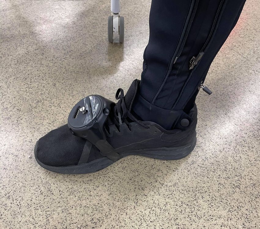
1.6 Foot Movement Detection Module
The unit responsible for the automated opening and closing of the tailgate is called
the Foot Movement Detection Module. Internally at Volvo Cars, it is known as
the FMDM. This project was proposed from Volvo Cars in order to support their
development of the unit. The final prototype of the project is intended to be used
during calibration and testing activities by engineers working with the function.
The prototype will be used as a tool to activate the sensors of the module. The
project outcome will thus indirect promote the future development of the function
by enabling new test procedures of objectively repetitive kicking motions performed
by a robot.
In order to detect and execute on triggering motions by an approaching object, the
FMDM operates by a combination of motors and sensors. Due to a non-disclosure
agreement with Volvo Cars, no further information of the functionality or specifica-
tion of the module will be included. However, essential information of the triggering
sequence is that the sensors will react to the following parameters of an approaching
object:
• Speed
• Material
• Geometry
These parameters constituted the basis for the product development processes of
achieving correct sensor activation with the prototype. Out of these parameters,
the speed was the main focus. The main reason for this being that the function-
ality of having a sufficient speed for sensor activation was a feature that would be
51. Introduction problematic or not even possible to add to the final prototype in the later stages of the project. The process of adapting an appropriate geometry and used material for the final prototype is more flexible and the parameters are thus seen as secondary to the speed. 1.7 Demarcations The main objective of the project was to develop a prototype that can demonstrate the function that was asked for by Volvo Cars in the project proposal. Thus, there was no intention to developed a product ready for the outer market. No potential external customers were be taken into account when developing the prototype. The requested function was one where a robot is able to receptively and with high ac- curacy reproduce identical kicks to those previously performed by a human. This entails that the project covers two main areas, motion tracking and robot move- ment. Regarding the motion tracking, there should not be any restrictions of which type of kick is being recorded by the operator. This means that when the operator is placed behind a vehicle and performs a kick, the full trajectory of the motion should be captured. However, practical factors have to be considered in order to ensure satisfactory recreation of the kicks. If the robot that will recreate the kicks is stationary placed behind the car, the reach of the robot, i.e. the total length of the robot when fully extended, will be a limiting factor. Some consideration of the length of the recorded trajectories will thus have to be made. The second area is the robot movement. The function asked for by Volvo Cars is a robot that can produce repeated kicks, identical to each other when objectively compared. This will be used as a tool internally to develop the FMDM function through different test activities. The scope of the project includes to create the tool. Thus, the project does not cover the process of developing the FMDM function itself by creating and performing the activities where the tool is used. Also, the project will not make any efforts to communicate or read the sensor output of the FMDM sensor. The only interaction with the car and the FMDM sensor will be performing kicks underneath the bumper with a robot, where the outcome can be either a successful or unsuccessful openings of the tailgate. As stated in the scope for the master thesis project, the intended time period is one semester, representing 30 credits and approximately six months [6]. There was no available pre-set budget for the project from either the university or the company. This resulted in that some consideration were made to cost and time during the project to ensure the expected completion. One decision where this became relevant was when procuring equipment for the motion tracking techniques. The project was able to procure the desired equipment from within the Volvo Cars organization. This saved both cost and time compared to procuring similar equipment from an external source. 6
1. Introduction

1.8      Additional aspects of the project
In order to ensure that the project work and all its outcomes maintained the highest
professional and ethical standard, the IEEE Code of Ethics was considered through-
out the project [7]. The list of ten guidelines represents a framework of how to act
as a professional. One prominent item on the list for this project was the following:

“3. to avoid real or perceived conflicts of interest whenever possible, and to disclose
them to affected parties when they do exist;” [7].

The project work was conducted at Volvo Cars. This means that the author had
a responsibility both towards the company and Chalmers University of Technology.
One issue that made this aspect relevant for the project work relates to the non-
disclosure agreement that was signed with Volvo Cars. The agreement prevents
an in depth presentation of the FMDM unit. As this was the main component of
the car that the project work focused on, a compromise had to be done to include
sufficient information about the FMDM unit to understand the background and
the implementation of the project without exceeding the boundaries of the non-
disclosure agreement.

1.8.1     Social aspects
As stated in Section 1.3, the aim of the project was to mechanically recreate a kick
performed by a human. This in turn will result in an operation where a task previ-
ously performed by a human is instead executed by a robot and thus the operator
gets replaced. One could argue for that performing a large amount of repetitive
kicks is not a productive engineering activity. Replacing the human kicker with a
robot will release the engineer that is currently performing this task to work with
other activities. This brings the potential to promote the development of the FMDM
function in better ways that what is currently being performed. The introduction
of a kicking robot will also generate a statement of investment towards the develop-
ment of the FMDM function. It will enable new testing activities for the engineers
working with the function, that are currently not possible to be performed. In or-
der to work with the full process of recording human movement and recreating the
trajectory with a robot, knowledge about how to use the hardware and software is
necessary. Introducing the robot as a tool to the group working with the FMDM
sensor will thus generate one or multiple new roles. Having knowledge about the
motion recording and robot programming will be added to the list of responsibilities
that are distributed within the team.

1.8.2     Ecological aspects
In the short term, introducing a robot to be used in the testing and calibration
of the FMDM sensor will have a negative impact on the carbon footprint of Volvo
Cars. The resources to manufacture the robot, the energy consumption while using
it and the disposal of the robot all need to be taken into consideration during the

                                                                                     7
1. Introduction assessment. The development work of testing and calibrating the FMDM sensor is usually performed on a single vehicle from each car model, including the different bumper designs for different trims of the same model. One example is the difference in bumper design for a V90 Inscription and a V90 Cross Country. This adds to a few dozen different bumper designs in total where the robot would be used. If the robot is introduced as a tool to calibrate the FMDM sensor, separate calibration would be performed for all models. The values and settings from the calibration are then downloaded to all newly manufactured cars leaving the factories. The hardware inside the FMDM unit also undergoes testing at Volvo Cars, even though some of the lifetime and reliability tests are performed by the supplier providing the module. In 2020, Volvo Cars sold 661 713 cars globally [8]. Not all sold cars include the automatic tailgate opening, but any potential issues related the hardware or software of the FMDM unit could bring a huge carbon footprint impact due to the large number of cars it would affect. If a car is required to visit a dealer to change the FMDM module due to hardware failure or to update the software because of inadequate sensor calibration, the carbon footprint of the robot, that brings the potential to avoid the issues due to implementing better testing methods, will be neglectable. 8
2
               Technical Background

This chapter presents more detailed information about the areas the project will
deal with in the later chapters of the report.

2.1      Fundamentals of imitation
As described in 1.3, the motion of a human will be the basis for the succeeding
mechanical movement. A description of the event that occurs may thus be that a
robot imitates a human. A detailed definition was introduced by Mitchell, where
the following requirements needs to be satisfied for imitation to be recognized [9]:

  1.   Something C is produced by an organism and/or machine, where
  2.   C is similar to something else M,
  3.   Registration of M is necessary for the production of C, and
  4.   C is designed to be similar to M.

By this definition, the human motion represents the model M and the robot move-
ment the copy C.

2.2      From motion recognition to reproduction
An approach to human motion imitation is presented by Kulić [10]. Her work covers
a presentation of the key methods for first observing and later modeling of human
movement, as well as the reproduction of the movement by humanoid robots. She
describes that the processing pipeline of human motion imitation can be divided
into four stages.

Figure 2.1: The processing pipeline for human motion imitation [10].

                                                                                  9
2. Technical Background
The first stage of Motion recognition involves observing and recording motion. To
achieve the highest accuracy, this is typically performed with motion capture, mean-
ing small markers are placed on a human body. The 3D position of the markers are
captured by a set of cameras, resulting in a data set of the Cartesian trajectory
(x,y,z positions) for each marker over the duration of the motion. The second stage
of Pre-Processing involves removing noise, interpolating missing marker data and
extracting relevant segments of the motion. In order to convert the Cartesian data
set into a kinematic model used by a robot or a human demonstrator, inverse kine-
matics are typically used. To put this into context, the study of motion where the
cause of the motion is not included, such as torques and forces, is known as kinemat-
ics [11]. Using the kinematic equations to determine the required motion of a robot
to reach a desired position, is known as inverse kinematics. When applying inverse
kinematics to the Cartesian data set, a joint configuration with calculated joint an-
gels is generated based on desired end position of the robot or human demonstrator.
A Model of the movement is created in the third stage. Kulić describes three classes
of approaches for generating models:
1. Direct human trajectory reproduction with separate postural control.
• This approach uses a reference trajectory, containing joint angle time se-
ries that are obtained from the motion capture of a human movement. A
control strategy is formulated to follow the reference trajectory as closely
as possible.
2. Motion primitive-based approach.
• This approach is based on the notion that human movement can be de-
composed to a set of primitive actions, known as motion primitives. The
motion primitives are pre-computed motions that the robot or human
demonstrator can execute. The approach is then to learn the models to
sequentially transition between valid motion primitives from the given
state to reproduce humanlike movement.
3. Control policy approach.
• The aim of this approach is to generate a learning system, whose goal is
trying to imitate the control system used to generate human movement.
Once a control system, or policy, is known, it is applied to the robot or
human demonstrator to generate humanlike movement. One method of
generating a control policy is by using reinforced leaning. The reinforced
learning framework includes iterative testing with a robot, where success-
fully executed actions are rewarded.
The forth stage refers to the Reproduction of the movement with a robot or a hu-
manoid. This is performed by using the developed model together with additional
control elements.
102. Technical Background
2.3 Computer aided design
CATIA V5 is the preferred computer aided design (CAD) software at both Volvo
Cars and Chalmers University of Technology. It is developed by Dassault Systems.
The software offers a variety of built-in functionality, useful for a range of design
tasks. A function relevant for the project is one where coordinates may be imported
to the software and automatically generate geometries based on the input. The
function utilizes a pre-configured macro in a Microsoft Excel sheet and is a part of
the installation directory of CATIA V5. The coordinates entered in the sheet need
to have a positive value in order for CATIA V5 to accept them. The name of the
Excel sheet is GSD_PointSplineLoftFromExcel. The macro provides three options
along with the coordinate import:
1. CreationPoint
• The coordinates in the Excel sheet are imported as a point cloud. There
are no interconnections between the points in the cloud.
2. CreationSpline
• The coordinates in the Excel sheet are imported as a point cloud. In
addition to this, a spline is created between the start and end point in
the list of coordinates. A curve fit is used to connect all data points in
the spline. Multiple lists can be imported simultaneously and generate
individual splines.
3. CreationLoft
• The coordinates in the Excel sheet are imported as a point cloud, with
splines connecting the points. Multiple splines generate a multi-section
surface (loft). The surface connects the start and end spline in the list of
coordinates. A curve fit is used to include all splines in the loft. Multiple
lists can be imported simultaneously but only one loft is generated.
113
Method
This chapter presents the methodology of the project. It was applied in such a
way that the objectives of the project and their potential solutions were met in
an effective way, in order to reach an appropriate final result. The framework of
the methodology consists of a general solution oriented product development. The
methodology of the project is presented by the flow chart in Figure 3.1 below. A
more detailed description of the tasks are presented in the succeeding sections.
Literature study of Procure chosen Find suitable data
Develop procedure to
motion tracking motion tracking type towards robot
record human kicks
techniques device interface
Execute recorded Adapt robot to
motion data with achieve sensor
robot activation
Literature study of Test robot with motion
Procure chosen robot
robot applications trajectory inputs
Figure 3.1: Flow chart of the project work
The related work was an inspiration for the development process in the project.
By using a Cartesian approach for the motion capture, as suggested by Nakamura,
Lee and Ott [3], the output data would be in a usable format to be processed in
a CAD software. As demonstrated by Holubek et al. [5], geometries can be used
for generating trajectories when imported to an offline robot programming software.
When applying the theory to this project, a CAD software could be used as an
intermediate step between the motion capture and the robot movement. In Section
3.6.2.1, the method is implemented by using the CAD software CATIA V5. In
order to perform accurate motion tracking, Jung, Kim and Lyou [4] proposes to use
a hybrid system consisting of two motion tracking technologies. This approach was
implemented in the development process of this project as two different technologies
were used during the initial testing, described in Section 3.4.1.
123. Method
3.1 Current solutions
A literature study of the current solutions for motion tracking and robot movement
were performed. The study included research projects and existing products on the
market.
3.1.1 Motion tracking
Motion tracking can be performed in various ways. What is a shared characteristic
between different techniques is the ability to express the location of a point in space
at a specific time. This point in space is specified by three Cartesian coordinates,
namely x(t), y(t) and z(t). If only the position of the point is requested, it is called a
3 Degrees of Freedom (DoF) tracking problem [12]. If the orientation of the point is
also considered, three degrees of freedoms are added, resulting in a 6 DoF problem.
In order to fully specify the position of a rigid body, both position and orientation
is required, which corresponds to 6 DoF [12].
3.1.1.1 Tracking techniques
When describing available systems for motion tracking, they can in a simplified way
be categorized into two main areas: camera based and sensor based systems. Among
these systems, there are three predominant techniques to capture motion [13]:
1. Video recordings
• This solution uses a single or multiple cameras to record the motion. With
the help of computer vision applications, relevant features are extracted
from the video.
2. Optical, infrared motion capture
• Reflective markers are placed on the moving object. By using multiple
infrared cameras, the position of the reflective markers can be determined.
3. Inertial measurement units (IMUs)
• The units consists of gyroscopes, magnetometers and accelerometers. To-
gether, they can be used to determine the position and orientation of the
unit.
Performing motion capture with a single camera primarily limits the solution to two
dimensions [13]. A certain camera position may enable horizontal capture of a mov-
ing object but it will have limited capability to report the vertical movement from
the camera. This limitation can be overcomed by adding multiple cameras. A 3D
representation of a motion, recorded by multiple cameras, can be created with data
fusion software. Figure 3.2 shows a generated 3D model from two moving bodies
recorded with a single RGB camera.
133. Method Figure 3.2: Multi-person 3D motion capture with a single RGB camera [14]. Optical motion capture requires multiple cameras and a calibration process of the system before recordings are possible. When used outside any dedicated test en- vironment, this brings a number of problems. It does not allow for instantaneous motion capture as there needs to be an installation process of the system. After the installation, any changes to the camera placement may cause inaccuracies to the motion capture. The area of which objects can be traced is also limited to the number of cameras used and their placement in the test area. The reflective sensors on the moving object needs to be visible for the cameras at all times for complete motion capture. However, with an appropriate test setup, the optical system offers tracking of high accuracy and precision [13]. Figure 3.3 shows a simulated setup of a body with reflective markers standing in the center of a test area, surrounded by infrared cameras. Figure 3.3: Setup for Impulse X2 motion capture system [15]. Inertial sensors overcome many of the challenges posed to the camera based systems. As the sensors are an integral part of the unit itself, it is not limited to a test area surrounded by cameras. The method is therefore beneficial when recording 14
3. Method

movements in a real world application. IMUs were included in the test setup for
a biomechanical analyzis of a skier through a 10-gate slalom course [16]. Inertial
sensors inherit challenges with accurate positioning over longer recordings. The
sensors does not measure the position of the unit itself, but the rate of change it is
exposed to [13]. A satisfactory estimation of the units position can be made through
integration, but over time the position will suffer from drift. The drift in position
can be eliminated by adding supportive systems to the unit’s positioning, such as a
global positioning system (GPS) or an acoustic positioning system [17]. Figure 3.4
shows an avatar with multiple IMUs attached to it.

Figure 3.4: Multiple IMUs attached to an avatar [18].

In this project, only motion tracking through methods using optical infrared motion
capture and IMUs were considered. The reason for video recordings being excluded
is their inherent difficulty to report accurate positioning in three dimensions. As
the motion to be recorded was a kick next to and underneath the bumper of a car,
additional visual obstacles would be introduced for the video camera system. In
order to accurately reproduce the kick, all three directions of motion will be equally
important. The optical infrared motion capture can be adapted so the infrared
cameras have full visuals of the human leg even under the bumper. When using
IMUs, no external tracking equipment is needed and no limitations are put on the
visibility of the leg.

                                                                                   15
3. Method 3.1.1.2 Motion tracking in virtual reality A key component of a virtual reality (VR) system is digitizing human movement and make it usable in a computer software. Proper motion tracking of a human is elementary for a successful system. VR applications utilizing motion tracking are being used in a number of different areas such as gaming, virtual prototyping and training for medical and military scenarios. It is the same techniques as described in the previous Section 3.1.1.1 that enable motion tracking in VR [19]. Optical tracking is performed by using infrared cameras, also known as base stations when used in a VR application, to determine the position of the connected equipment to the VR system. Examples of equipment that can be tracked by the base stations is a VR headset, enabling the user to visually experience the VR environment, or a controller that allows the user to interact with environment. Non-optical tracking techniques attach IMUs to the body being tracked, either as individual units or incorporated in clothing. When incorporated in a full body suit, motion capture for the entire body is generated. 3.1.1.3 Available products for motion tracking in virtual reality In the current market, there are a number of companies offering motion tracking in VR by different tracking techniques. Products using IMUs include full body suits such as the ones from Xsens [20] and Teslasuit [21]. Included in the purchase of each suit, is access to specialized software developed by the companies. The software en- ables easy calibration, playback and reprocessing of the motion capture as well as real-time visualization of the movement [20]. The cost of the mentioned full body suits using IMUs for motion tracking is in the region of 100,000 SEK. One popular system using optical, infrared motion capture to enable tracking in VR is from the company VIVE. The set includes a headset, two base stations and two controllers which allows visualization and interaction with the VR environment. The general recommended computer specifications for running the system on a PC is according to VIVE [22]: Graphics: NVIDIA® GeForce® GTX 1060 or AMD Radeon™ RX 480, equivalent or better. Processor: Intel® Core™ i5-4590 or AMD FX™ 8350, equivalent or better. Memory: 4 GB RAM or more. The cost of an equivalent system including a headset, two base stations and two controllers is in the region of 10-15,000 SEK. 16
3. Method
3.1.2 Virtual reality platforms
One of the leading platforms for creating interactive, real-time content is Unity[23].
Unity allows for creation of 2D, 3D and VR applications and games. Unity support
a wide range of VR application plug-ins where functionality is added to the plat-
form. By creating projects, the user is able to work and interact with the content.
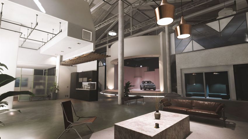
In 2021, Volvo Cars released a project using the Unity platform [24]. The Unity Au-
toShowroom Template, shown in Figure 3.5, allows the user to explore and interact
with a 3D model of a vehicle with basic functionality, such as opening and closing of
doors. The interior and exterior views of the car, as well as the material selections
in the showroom is of high detail to ensure an authentic visualization of the vehicle.
Figure 3.5: Unity AutoShowroom Template of a Volvo XC40 Recharge P8 AWD.
The AutoShowroom Template consists of multiple GameObjects. In Unity, GameOb-
jects are the fundamental objects that represents props, characters and scenery [25].
They do not add any functionality themselves, but act as containers for Components
that implement a desired function. In Figure 3.6, the GameObject is represented
by the colorful coordinate axes.
Figure 3.6: A GameObject placed inside a cube [26].
173. Method The position and orientation is always known for a GameObject in Unity. It is being tracked by a Transform component, as can be seen in Figure 3.7. Figure 3.7: 6 DoF positioning for a GameObject in Unity. The Transform component positions the GameObject in 6 DoF in the virtual envi- ronment. By using a motion tracking system incorporating a VR environment with GameObjects, the project did not have to develop its own platform to generate and record of motion capture. As shown in the stuby by Nakamura, Lee and Ott [3] presented in Section 1.2.1, developing such a platform would have greatly extended the scope of the project due to its complexity. The VR platform also enables use of equipment for high accuracy tracking from different tracking techniques. At this point of the project, no decision had been made about whether to use optical in- frared tracking or IMUs in the final solution. With the decision to utilize VR as the platform came the opportunity to test both technologies before making a decision. 3.1.3 Robotics Robotics can be defined as the design, construction, and use of machines (robots) to perform tasks initially performed by human beings [27]. Robots are widely used in industries where repetitive tasks are performed, often with the intention of succes- sively replacing the human labor. Depending on the application, many companies offer a large lineup of products that are able to perform a range of different tasks. Some eminent companies within robotics are for example Boston Dynamics [28] and ABB Robotics [29]. 3.1.3.1 Robot configuration A robot mechanism, is a system of rigid bodies connected by joints [30]. The solid bodies of the robot are also known as links. Depending on the configuration, the amount of joints and links that are connected will vary. As mentioned in 3.1.1, a defined object in space has 6 DoF. DoF is also used when describing the way in which a robot can move. The total number of independent displacement or aspects of motion is defined as the degrees of freedom for the robot [31]. On the current market, there are robots with 4, 6 and 7 DoF [32]. For this project, only robots with 6 and 7 DoF were considered. A robot with 4 DoF would be insufficient. This is because it is not able to maintain a fixed orientation of axis 6, shown in Figure 3.8, when moving in three dimensions. A rotation of axis 6 will follow the rotation of axis 1 when moving sideways. The objective of the robot in this project was to reproduce a human kick and a robot with 4 DoF is too limited in its degrees of freedom for representative kicking motion. 18
3. Method

Figure 3.8: Model of IRB1300, a 6 DoF articulated robot from ABB [33]

3.1.3.2   Robot programming
There are different methods by which a robot can be programmed to perform move-
ment. Two general areas of the methods include online and offline programming.
Conventional online programming is carried out by robot operator, guiding the robot
though a desired path [34]. The operator uses a teach pendant to jog the joints of
the robot and is responsible for maintaining the desired orientation and position
of the robot in 6 DoF. Chosen key points by the operator are recorded and saved
to the robot controller. This method is known as the lead-through method. Of-
fline programming (OLP) instead uses computer software to create robot programs,
which are later downloaded to the physical robot. Virtual 3D models are used to
generate and simulate robot movements. The program can be refined and fine-tuned
in the software before being downloaded to the robot. OLP offers many advantages
over the online programming method [34]. One of them being that OLP is more
flexible than online programming, resulting in changes to the robot program can be
incorporated more quickly.

There are many OLP software to chose from. It is common for companies pro-
viding robotics solutions to offer their own program. Three examples of this are
RobotStudio by ABB Robotics [35], RobotExpert by Siemens [36] and K-ROSET
by Kawasaki Robotics [37]. The mentioned OLP software are optimized for robots
manufactured by the same company and they contain a virtual library of their own
robot models. It is thus appropriate to choose a hardware and software combination
from the same company when planning the robot solution.

                                                                                19
3. Method 3.1.3.3 Robot types Two common robot types are known as collaborative robots (cobots) and industrial robots. Collaborative robots are designed to work alongside humans. Cobost enable less experiences operators without previous training the use of robots, due to their simplicity [38]. They are usually of smaller size and are known for being easy to con- figure and work with. One feature unique for cobots during online programming, is the ability for operators to push the robot by hand and record a lead-through program to the robot controller. The second type is industrial robots. There are four sub-groups of industrial robots, but the most known type is an articulated robot. They are classified based on the amount of axes or points of rotation they have. A 6-axis is the most common configuration and one example of such a robot can be seen in Figure 3.8. Known advantages of the articulated robots are dexterity, reach and flexibility [32]. When comparing cobots and industrial robots, the later group was more suitable for this project. Some of the main advantages for cobots, including the easy to use lead-through programming and the ability to work alongside humans would not be applicable in this project. As the trajectory for the robot movement would be based on an already recorded motion by a human, it was expected to be too inaccurate to generate the program through online lead-through programming when comparing the trajectory to the original motion. An OLP software is more suited to work with when generating the robot trajectory. Among the industrial robots, an articulated robot was the most appropriate for the intended robot solution. Using the attribute of reach as an example, it was one of the most important parameters for the robot. The reach determines the length of the trajectories the robot is able to follow without making any compromises or adding limits to the original human movement. 3.2 Requirements list The requirements list was established based on a discussion with Volvo Cars in com- bination with a general understanding of the problem and the scope of the project. The list consists of demands that needs to be solved by the solution as well as wishes that should be solved to the best extent possible, but are not necessary for solving the main objective of recording and recreating human motion. The requirements targeted both the motion capture and robot solution. 20
3. Method

    Area                                          Criteria                                         Verification method                                       Target value                              Demand/Wish
                 1. Convenience
Robot            1.1 Allow operator in close proximity during operation                      Product design                    Operator located in the same room                                       Wish
Robot            1.2 Solution moveable within the test area                                  Product design                    Reasonable effort to relocate solution                                  Demand
Robot            1.3 Easy to operate with reasonable physical effort                         Subjective and functional testing Only one operator is required                                           Wish
                 2. Functionality
Robot            2.1 Activate FMDM sensor on a vehicle from Volvo Cars                       Functional testing                Useable solution                                                        Demand
Robot            2.2 Perform a representative kick as by a human leg from the knee down      Functional testing                Comparable kick trajectories by human and robot                         Demand
Robot            2.3 Perform a kicking motion by following a trajectory from an input file   Product design                    The robot motion has a strong resemblance to the input file             Demand
Robot            2.4 Perform a kicking motion in normal speed                                Functional testing                The robot motion can follow a set speed                                 Demand
Robot            2.5 Perform a kicking motion in various speeds                              Functional testing                The robot motion can vary between different speeds during motion        Wish
Robot            2.6 Allow interchangeable shoe attachments                                  Product design                    Any shoe can be attached to the solution                                Wish
Robot            2.7 Automated test programs including many kicking motions                  Product design                    The robot can perform many kicking motions without interupption         Wish
Motion Capture   2.8 Capture horizontal body movement                                        Functional testing                No limitation in the motion tracking                                    Demand
Motion Capture   2.9 Capture vertical body movement                                          Functional testing                No limitation in the motion tracking                                    Demand
Motion Capture   2.10 Capture angular movement from joints                                   Functional testing                No limitation in the motion tracking                                    Wish
Motion Capture   2.11 Record timelapse of body movement                                      Functional testing                The timelapse can be used to determine the speed of the recorded kick   Wish
Motion Capture   2.12 Body movement is expressed in a data set                               Product design                    Data from a run can be explicitly expressed                             Demand
                 3. Reliability
Robot            3.1 Not block the movement of the tailgate after sensor activation          Functional testing                The robot does not interfere with the tailgate at any time              Demand
Motion Capture   3.2 Test setup enables repeatable outputs                                   Functional testing                No use of temporary equipment in test setup                             Demand
Motion Capture   3.3 Test setup can be used by different body types                          Functional testing                Any test person may be subject to motion capture                        Wish
                 4. Durability
Robot            4.1 Repeatable positioning in relation to current test vehicle              Product design                    The solution can be accurately positioned in the test environment       Demand
                 5. Ergonomics
Robot            5.1 Not make a lot of noise                                                 Subjective and functional testing The operator does not experience the solution as intrusive              Wish

Table 3.1: Initial requirements list

The robot will be stand-alone from any vehicle it interacts with and thus only 2
out of 20 requirements included any criteria with a car. First, it is performing the
main function, 2.1 Activate FMDM sensor on a vehicle from Volvo Cars. Second,
is the adaptation to the car’s response of the sensor activation, 3.1 Not block the
movement of the tailgate after sensor activation.

In order to evaluate which motion tracking equipment and robot model that was
suitable to use in the project, presented in the next Section 3.3, the requirements
list acted as a basis for the decisions.

                                                                                                                                                                                                                21
3. Method
3.3 Procurement of motion tracking equipment
and robot
Presented below is the equipment the project used during the initial testing activi-
ties.
3.3.1 Motion tracking equipment
The department known as Open Innovation Arena at Volvo Cars was contacted in
order to get access VR equipment and software. The project was allowed to use
licenses enabling work with a VR environment in Unity and got access to various
high-end equipment used for the initial testing of a motion tracking solution. The
specifications of the computer being used was:
Graphics: NVIDIA® GeForce® RTX 2080 TI.
Processor: Intel® Core™ i9-9900K.
Memory: 32 GB RAM.
Equipment using both optical infrared motion capture and IMUs became available.
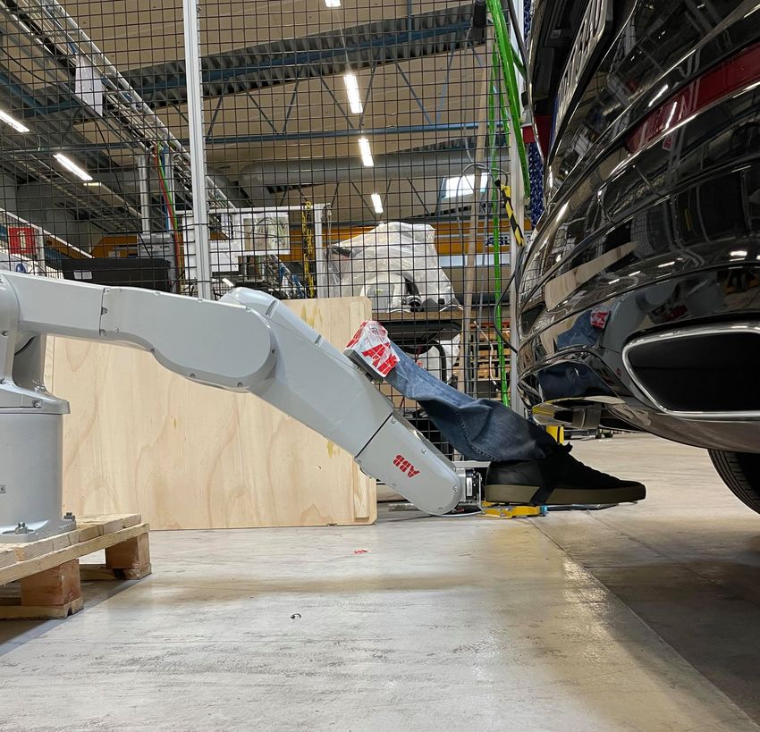
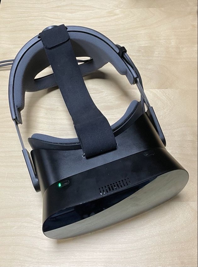
The setup with a headset, a tracker and two base stations, shown in Figure 3.9,
enabled optical infrared tracking.
(a)Valve Index Base Sta- (b) HTC Vive Tracker (c) Varjo VR-1 Headset
tion [39] [40] [41]
Figure 3.9: Equipment enabling optical infrared motion capture
The equipment to perform motion tracking using IMUs was the Teslasuit. The
suit can be seen in Figure 3.10. The suit includes ten integrated IMUs, where
six are placed in the jacket and four are placed in the pants. The suit allows
integrated skeletal and 3D kinematic motion capture in the virtual environment,
which is visualized by a full body avatar [42]. As there are no IMUs attached to
the feet of the user wearing the suit, its positions are estimated based on the pose
of the virtual avatar.
223. Method
Figure 3.10: Teslasuit [21].
The available equipment using both optical infrared motion capture and IMUs fulfill
the demands of the motion capture presented in the requirement list, Table 3.1. The
demands of the solution includes capturing both vertical and horizontal movement,
criteria 2.8 and 2.9, which is not an issue when using either of the methods. It also
covers the requirement of repeatable outputs, criteria 3.2. As the same equipment
will be used and the test setup can be recreated for different motion recording
sessions, this criteria is also fulfilled. The last demand of the motion capture system
is the ability to express the body movement in a data set, criteria 2.12, as this will
be used as input for the robot movement. When utilizing the VR platform Unity
for both solutions, the captured motion is digitized and thus becomes available to
export as a data set when using a functional motion recording method.
3.3.2 Robot
The company ABB Robotics was contacted in order to get access to an articulated
robot. Two different aspects of this decision was that ABB offers their own offline
robot programming software RobotStudio [35], as well as having a large library of
different robots that would fulfill the demands for the robot in the requirements list,
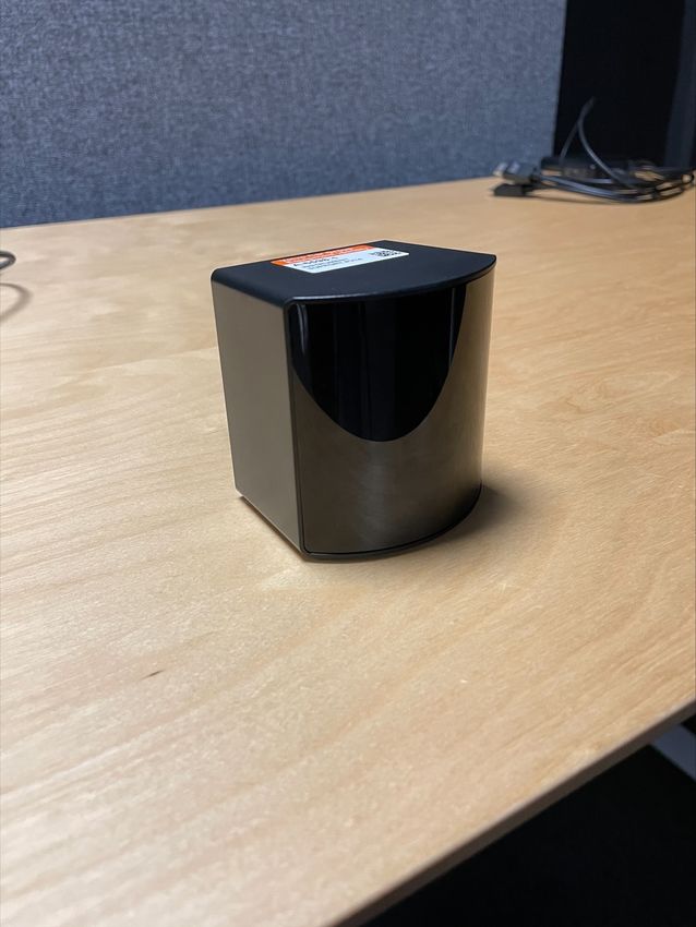
presented in Table 3.1. The robot acquired by the project was the model IRB1200,
shown in Figure 3.11.
233. Method
Figure 3.11: Robot model IRB1200 from ABB.
The full specification of the robot can be found in Appendix A.1. Key specifications
of the model that was important to the project are the following:
1. 6-axis
2. 0.9 m reach
3. 52 kg
In the requirements list in Table 3.1, there are four demands that are possible to
fulfill by using a 6-axis articulated robot. These criteria are 2.1 activate the FMDM
sensor, 2.2 perform a representative kick as by a human from the knee down, 2.4
perform a kicking motion in normal speed and 3.1 not block the movement of the
tailgate after sensor activation. The robot IRB1200 can perform motions in various
speeds and has enough axles to represent a human kick from the knee down. Criteria
3.1 can be fulfilled by continuing a motion away from the tailgate after the FMDM
sensor activation, as the tailgate is not opened instantaneously. The weight of
52 kg is subjectively not considered heavy enough to restrict moveability within a
test area, as criteria 1.2 states. Because the robot is moveable, it is also possible
to identically position the robot during different test session and for different test
vehicles. As criteria 4.1 states, repeatable positioning is thus achievable. Criteria
2.3, to perform a kicking motion by following a trajectory from an input file, is
possible by implementing a suitable method with the OLP software RobotStudio.
The program has a virtual model of the IRB1200 in its library, which can generate
robot programs that can be downloaded to the physical robot. The specification of
0.9 m reach is referring to the distance from the center of the robot to the outer
edge of the robotic arm when in a fully extended position. 0.9 m is subjectively
not considered to be a significantly limiting factor when assessing the length of the
trajectories the robot can perform.
24You can also read