Deliverable D2.2 Site facilities planning - 5G European Validation platform for Extensive trials - 5G EVE
←
→
Page content transcription
If your browser does not render page correctly, please read the page content below

5G European Validation platform for Extensive trials

             Deliverable D2.2
          Site facilities planning
Project Details
Call                             H2020-ICT-17-2018
Type of Action                   RIA
Project start date               01/07/2018
Duration                         36 months
GA No                            815074

                                  Deliverable Details
Deliverable WP:                  WP2
Deliverable Task:                Task T2.1
Deliverable Identifier:          5G_EVE_D2.2
Deliverable Title:               Site facilities planning
Editor(s):                       Rodolphe Legouable
Author(s):                       R. Legouable, K.Trichias, Y. Kritikou, D. Meridou, V.
                                 Stavroulaki, V. Kosmatos, A. Skalidi, G. Loukas, N.
                                 Kostopoulos, K. Kravariotis, A. Tzoulis, E.
                                 Paraskevakis, G. Agapiou, S. Morant, M. Corriou, L.
                                 Roullet, D. Deprey, R. Knopp, M. Tognaccini, F.
                                 Sorvillo, A. Germanò, I. Berberana, J.M. Rodera, J.J.
                                 García-Reinoso, A. Sessler, M. Boldi, L.Stroppolo, S.
                                 Canale, G. Ciucciarelli, V. Suraci

Reviewer(s):                     E. Kowalczyk, K. Kravariotis
Contractual Date of Delivery:    01/11/2018
Submission Date:                 31/10/2018
Dissemination Level:             PU
Status:                          1.0
Version:                         Final
File Name:                       5G_EVE_D2.2

                                               Disclaimer
     The information and views set out in this deliverable are those of the author(s) and do not
     necessarily reflect the official opinion of the European Union. Neither the European
     Union institutions and bodies nor any person acting on their behalf may be held
     responsible for the use which may be made of the information contained therein.

                                                                                                   ii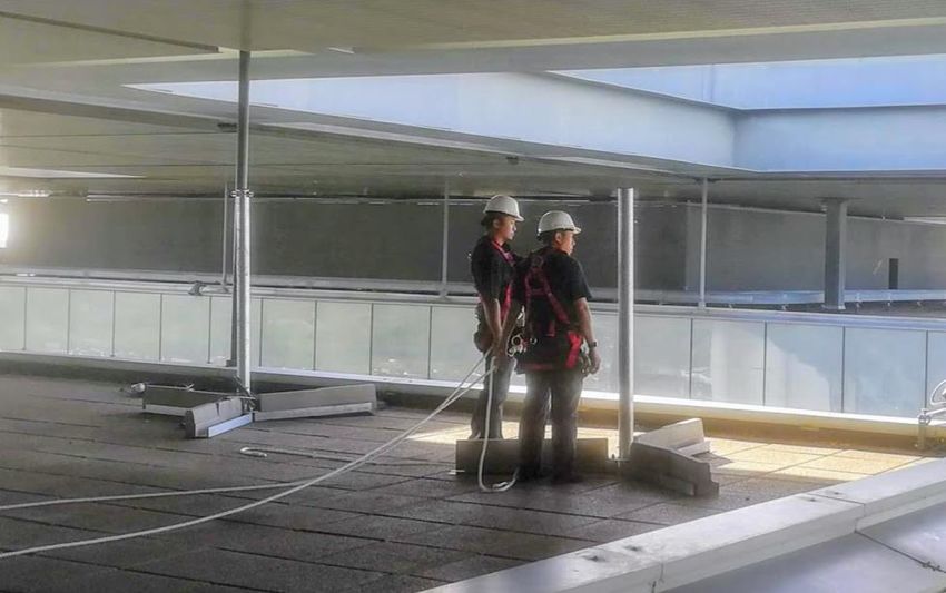
Deliverable History
Version   Date             Modification                      Modified by
V0.1      02/07/2018       First draft                       R. Legouable
V0.2      19/09/2018       Greek site facility first input   N. Kostopoulos,
                                                             K.Kravariotis, D. Meridou,
                                                             K.Trichias, V. Kosmatos
V0.3      25/09/2018       Inputs from French site           R. Legouable, S. Morant
                           facility
V0.4      26/09/2018       New inputs from Greek site        K. Trichias, Y. Kritikou, A.
                                                             Skalidi, V. Stavroulaki, G.
                                                             Loukas
V0.5      26/09/2018       Inputs from the Italian Site      M. Boldi
V0.6      27/09/2018       Inputs from Eurecom               R. Knopp
V0.7      28/09/2018       Review of the French part         R. Legouable, J. M. Rodera
                           & Integration of the              Recio
                           Spanish part
V0.8      28/09/2018       New gantt chart insertion,        R. Legouable
                           Acronym, references,
                           Appendix
V0.9      01/10/2018       Conclusion Editing                R. Legouable
V0.10     03/10/2019       Nokia France contribution         L. Roullet, R. Legouable
                           & comments review

                                                                                            ii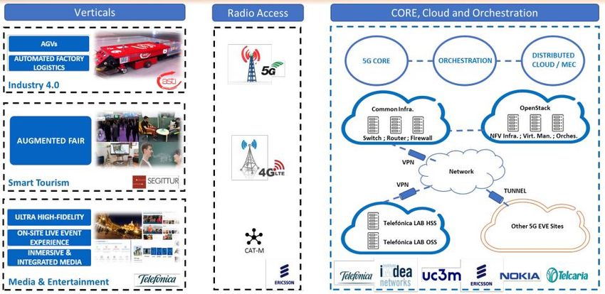
Table of Contents
LIST OF ACRONYMS AND ABBREVIATION............................................................................................................ V
LIST OF FIGURES ........................................................................................................................................................ VII
LIST OF TABLES ......................................................................................................................................................... VIII
EXECUTIVE SUMMARY ................................................................................................................................................ 9
1 INTRODUCTION ......................................................................................................................................................... 10
   1.1 STRUCTURE OF THE DOCUMENT ................................................................................................................................ 11
2 GREEK SITE FACILITY PLANNING ...................................................................................................................... 11
   2.1 INTRODUCTION .......................................................................................................................................................... 11
      2.1.1 Industry 4.0 – AGV use case oriented architecture ........................................................................................... 11
      2.1.2 Utilities use case – Smart grid fault detection & management ......................................................................... 11
      2.1.3 Smart city use case – Safety / Health / Home - Mobility ................................................................................... 12
   2.2 PLANNING ................................................................................................................................................................. 12
      2.2.1 Network infrastructure ...................................................................................................................................... 13
      2.2.2 Network management ........................................................................................................................................ 20
      2.2.3 Technologies ..................................................................................................................................................... 22
      2.2.4 User Equipment................................................................................................................................................. 23
      2.2.5 Deployment ....................................................................................................................................................... 24
      2.2.6 Platforms integration ........................................................................................................................................ 24
3 ITALIAN SITE FACILITY PLANNING.................................................................................................................... 29
   3.1 INTRODUCTION .......................................................................................................................................................... 29
      3.1.1 Smart Transport use case: architecture ............................................................................................................ 30
      3.1.2 Smart cities: Safety and Environment - Smart Turin......................................................................................... 30
   3.2 PLANNING ................................................................................................................................................................. 31
      3.2.1 Network infrastructure ...................................................................................................................................... 31
      3.2.2 Network management ........................................................................................................................................ 33
      3.2.3 Technologies ..................................................................................................................................................... 34
      3.2.4 User Equipment................................................................................................................................................. 34
      3.2.5 Deployment ....................................................................................................................................................... 34
      3.2.6 Platform Integration ......................................................................................................................................... 34
4 SPANISH SITE FACILITY PLANNING ................................................................................................................... 35
   4.1 INTRODUCTION .......................................................................................................................................................... 35
   4.2 PLANNING ................................................................................................................................................................. 35
      4.2.1 Network infrastructure ...................................................................................................................................... 35
      4.2.2 Network management ........................................................................................................................................ 39
      4.2.3 Technologies ..................................................................................................................................................... 41
      4.2.4 User Equipment................................................................................................................................................. 41
      4.2.5 Deployment ....................................................................................................................................................... 41
   4.3 RISKS ........................................................................................................................................................................ 42
5 FRENCH SITE FACILITY PLANNING .................................................................................................................... 42
   5.1 INTRODUCTION .......................................................................................................................................................... 42
   5.2 PLANNING ................................................................................................................................................................. 44
      5.2.1 Network infrastructure ...................................................................................................................................... 44
      5.2.2 Network management ........................................................................................................................................ 50
      5.2.3 Technologies ..................................................................................................................................................... 52
      5.2.4 User Equipment................................................................................................................................................. 52
      5.2.5 Deployment ....................................................................................................................................................... 52
   5.3 RISKS ........................................................................................................................................................................ 55
6 CONCLUSION .............................................................................................................................................................. 56

                                                                                                                                                                                    iii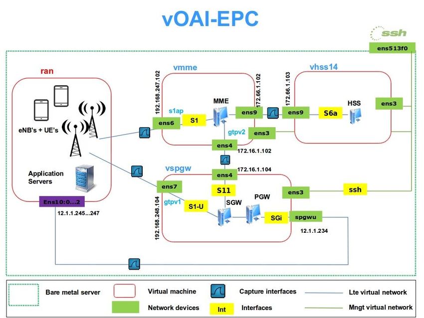
REFERENCES ................................................................................................................................................................. 57
APPENDIX A: GREEK SITE FACILITY PLANNING............................................................................................... 58
APPENDIX B: ITALIAN SITE FACILITY PLANNING ............................................................................................ 59
APPENDIX C: SPANISH SITE FACILITY PLANNING............................................................................................ 60
APPENDIX D: FRENCH SITE FACILITY PLANNING ............................................................................................ 61

                                                                                                                                                                            iv
List of Acronyms and Abbreviations
                                              MIMO       Multiple Input Multiple Output
          Third Generation Partnership        MME        Mobility Management Entity
3GPP
          Project
                                                         massive Mobile Type
                                              mMTC
5G        Fifth Generation                               Communication
AGV       Automated Guided Vehicle            NB-IoT     Narrow Band – Internet of Things
API       Application Programming Interface   NFV        Network Function Virtualization
          Autorité de Régulation des          NFVM       NFV Manager
ARCEP     Communications Electroniques        NFVO       NFV Orchestrator
          et des Postes
                                                         NFV Infrastructure Point of
BBU       Base Band Unit                      NFVI PoP
                                                         Presence
CA        Carrier Aggregation                 NR         New Radio
          Cloud Execution (Ericsson)          NSA        Non Stand-Alone
CEE
          Environment
                                              NSD        Network Service Descriptor
CIC       Cloud Infrastructure Controller
                                              OAI        Open Air Interface
CP        Control Plane
                                              ODL        OpenDayLight
CPRI      Common Public Radio Interface
                                              QoS        Quality of Service
C-RAN     Cloud Radio Access Network
                                              RAN        Radio Access Network
CU        Cloud Unit
                                              RAU        Radio Access Unit
DU        Digital Unit
                                              RD         Radio Dot
E2E       End-to-End
                                              RRC        Radio Resource Control
eMBB      Enhanced Mobile Broad Band
                                              RRH        Remote Radio Head
EPC       Evolved Packet Core
                                              RRU        Remote Radio Unit
          Evolved Terrestrial Radio Access
E-UTRAN                                       SA         StandAlone
          Network
FDD       Frequency Division Duplex           SDN        Software Defined Network

HSR       High Speed Rail                     SDR        Software Defined Radio

HSS       Home Subscriber Server              SW         SoftWare

HW        HardWare                            TaaS       Testing as a Service

IaaS      Interface as a Service              TDD        Time Division Duplexing

IoT       Internet of Thing                   UC         Use case

IRU       Indoor Radio Unit                   UE         User Equipment

KPI       Key Performance Indicator                      Ultra-Reliable Low-Latency
                                              uRLLC
                                                         Communications
LAN       Local Access Network
                                                         Universal Software Radio
LIDAR     LIght Detection And Ranging         USRP
                                                         Peripheral
LTE       Long-Term Evolution                 vCPU       Virtual Central Processing Units
MANO      Management and Orchestration        vEPC       virtual Evolved Packet Core
MCR       Mobile Cloud Robotics               vEPG       virtual Evolved Packet Gateway
MEC       Mobile Edge Computing               VIM        Virtualized Infrastructure Manager

                                                                                              v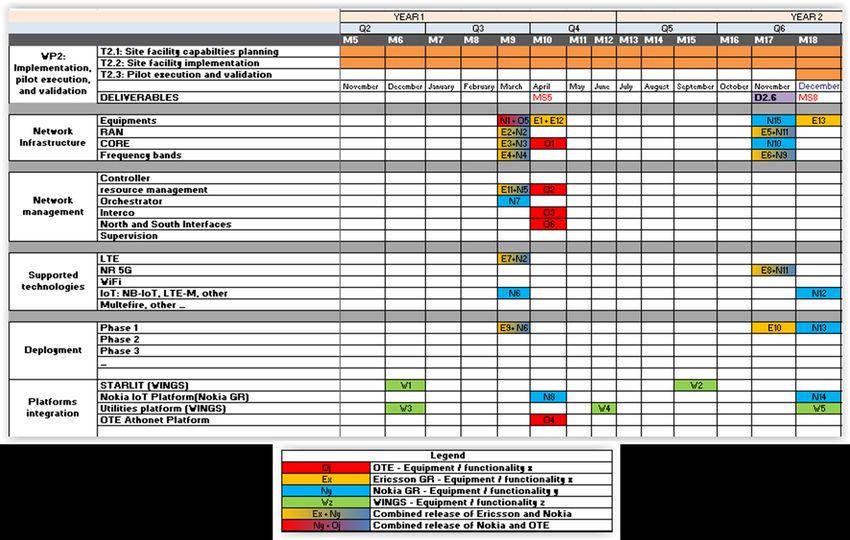
VM        Virtual Machine                   VPN   Virtual Private Network
VNF       Virtual Network Function          WAN   Wireless Access Network
VNF-FGD   VNF Forwarding Graph Descriptor
          Virtual Network Interface
VNIC
          Controller

                                                                            vi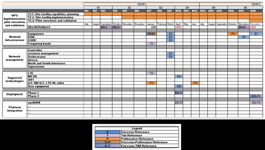
List of Figures
Figure 1: Global WP2 planning ......................................................................................................................... 10
Figure 2: General network architecture of the Nokia core & in-network data paths......................................... 14
Figure 3: Radio DoT architecture optimized for medium to large scale indoor deployments .......................... 14
Figure 4: a) Nokia Indoor Multi-Band FDD LTE small cell, b) Nokia small cells main architecture and
interfaces ........................................................................................................................................................... 16
Figure 5: Nokia AirScale Radio Access Elements ............................................................................................ 16
Figure 6: Athonet vEPC architecture................................................................................................................. 17
Figure 7: Option 3, including all three variants 3, 3a & 3x ............................................................................... 18
Figure 8: Overall network architecture .............................................................................................................. 18
Figure 9: Nokia cloud EPC Integration ............................................................................................................. 19
Figure 10: Enabling new extremely low latency dependent use cases (e.g. AR/VR) ....................................... 19
Figure 11: Evolved UTRA-NR Dual Connectivity (EN-DC) architecture ....................................................... 23
Figure 12: Envisioned deployment for the phase 2 deployment of the Connected ambulance use case ........... 24
Figure 13: Physical core infrastructure at OTE premises .................................................................................. 25
Figure 14: Logical architecture of the OTE testbed .......................................................................................... 25
Figure 15: Nokia IoT platform high-level architecture ..................................................................................... 26
Figure 16: Overview of STARLIT .................................................................................................................... 27
Figure 17: CATARACT high-level architecture and technologies ................................................................... 29
Figure 18: Flight rack system ............................................................................................................................ 32
Figure 19 5G New Radio Non Stand Alone ...................................................................................................... 32
Figure 20: Generic scheme of the 5G EVE Spanish site facility ....................................................................... 35
Figure 21: 5TONIC data center ......................................................................................................................... 36
Figure 22: 5TONIC laboratory facilities ........................................................................................................... 36
Figure 23: 5TONIC indoor experimental area .................................................................................................. 37
Figure 24: 5TONIC outdoor experimental area ................................................................................................ 37
Figure 25: 5TONIC showroom ......................................................................................................................... 37
Figure 26: 5TONIC masts at Distrito Telefónica .............................................................................................. 38
Figure 27: vEPC configuration in 5TONIC site ................................................................................................ 39
Figure 28: Phase 1 implementation of AGV centralized control ...................................................................... 41
Figure 29: French site facility architecture ........................................................................................................ 43
Figure 30: iFUN equipment............................................................................................................................... 45
Figure 31: Nokia research platform equipment ................................................................................................. 46
Figure 32: Front-end SDR ................................................................................................................................. 47
Figure 33: openairCN elements shown as three virtual machines ..................................................................... 48
Figure 34: *Wireless Edge Factory* architecture ............................................................................................. 48
Figure 35: VPN interconnection ........................................................................................................................ 51

                                                                                                                                                                     vii
Figure 36: Nokia 5G Airscale installation ......................................................................................................... 54
Figure 37: Nokia cloud infrastructure installation ............................................................................................. 54

List of Tables
Table 1: Orange Plug’in HW/SW resources...................................................................................................... 44
Table 2: French site facility frequency bands that are available for on-air transmission .................................. 49

                                                                                                                                                 viii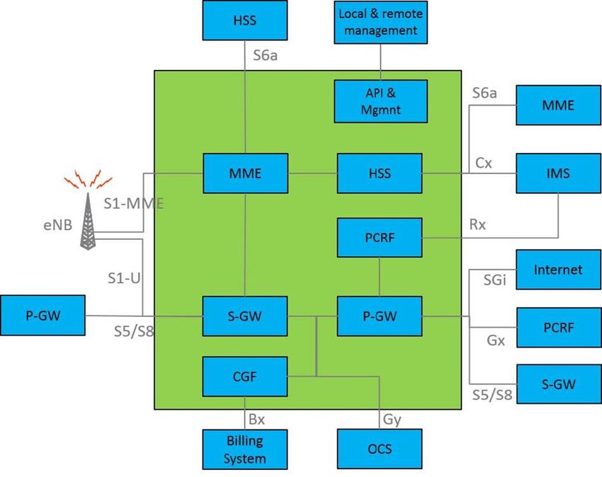
5G EVE (H2020-ICT-17-2018)

Executive Summary
The present deliverable describes the planning of each site facility deployment at least until April 2019. It also
gives some perspectives of updates that will occur after this date. April 2019 has been put at the first objective
since it corresponds to the initial access to the site facility for vertical hosting. Attached to this deliverable, we
have inserted an Excel file, with one sheet per site facility, giving the dates of availability for each
component/equipment that compose the integrated site facility. These components are referred via index
number in the Excel sheet, showing their date of availability. Then, in the document, a brief description of
each component is done as well as its methodology of implementation, testing and validation. More attention
is paid about the site facility integration. Indeed, since some site facilities are composed of several integrated
platforms regarding the use case they want to host, each integrated platform is detailed about the components
they are composed of, the KPI they plan to achieve and the methodology of integration they plan to apply.
The content of this document is complementary to the 5G EVE deliverable D2.1 [1], which describes more in
details the various site facilities. We just refer or take inputs coming from [1] to give information about the
site facilities architectures and components that integrate the platforms. Therefore, reading first [1] is a
prerequisite to better understand this document.

Deliverable D2.2                                                                            Page 9 / 63
5G EVE (H2020-ICT-17-2018)

1 Introduction
The objective of this document is to provide a roadmap for 5G EVE platform implementation (in terms of
components) over particular European site facility composing this platform. Then, planning for each
integrated platform is given as well as an overview of the different tests leading to the components' validation.
The global validation procedure for the E2E transmission allowing to host the verticals is explained.
For each site facility, the objective is to have a view of its roadmap through the main functionalities, and
updates that will be implemented in order to be able to host the initial access to participating vertical
industries for non-interworking use cases in April 2019. At this moment, the APIs and test tools will be not
yet available. Then, the integration of common tools developed in the project framework will be done
progressively.
Even if the focus is mainly done about the site facility status until April 2019, the perspectives of site facility
upgrades are envisaged after April 2019 as well. Indeed, since these improvements are dependent on the
equipment providers, the roadmap should be refined over the medium term.
Figure 1 recalls the global WP2 roadmap in a macro view with the different deliverables and milestones.
Among the milestones, MS5 that occurs in April 2019, corresponds to the initial access to site facilities
whereas MS8, end of 2019, to the moment where the site facilities will be interconnected and equipped to the
main tools for integrating external verticals, leading to the first version of E2E site facility. This first version
will be followed by the second one (MS9 in April 2020) and the third one (MS10 end 2020) with various
improvements that will follow the main specifications of 3GPP R16 release. The last version will describe the
final 5G Validation platform facilities achieved by 5GEVE project. Therefore, we propose a regular evolution
of this deliverable every 6 months from the first delivery of the platforms at the end of April 2019. The
various versions of deliverable will highlight the main site facilities evolution that will compose the E2E
facility.
For each site, we propose to map the main deadlines about components delivery on the calendar. We refer in a
specific Excel sheet per site facility, the availability of the site facilities components/equipment by giving in
this main word document their main functionality, their date of availability and how they will be tested and
validated in the integrated framework. Then, a specific section about the integrated platform is detailed for
each site facility, given the combination of the different components that will compose it. A description of the
main objectives of each integrated platform is carried out, giving the main KPIs that are expected.

                                         Figure 1: Global WP2 planning
An “inventory” of each 5G EVE site facility is given in [2] through the presentation of the detailed planning
of availability of the main components of each site. The components availability table [2] is also the basis for
the regular monitoring of the site facility implementation. It will be also updated during the project. Each
planning is also searchable in APPENDIXES until December 2019. Each component is referred by an index
number that is reported in the document to give information about it.
We move follow the same organization for each site facility for the detailed components/equipment reporting.
The attached excel file inventories the planning of each site facility through its main components.

Deliverable D2.2                                                                         Page 10 / 63
5G EVE (H2020-ICT-17-2018) 1.1 Structure of the document The main structure of this deliverable is as follows; Chapter 2 contains the planning of the Greek site facility, Chapter 3 contains the planning of the Italian site facility, Chapter 4 contains the planning of the Spanish site facility, Chapter 5 contains the planning of the French site facility. Finally, Chapter 6 makes a conclusion and recommendation. 2 Greek site facility planning 2.1 Introduction As described in detail in D2.1 [1], the Greek site will consist of platforms and components of Ericsson and Nokia in terms of the access and core networks. The RAN will consist of different nodes from Ericsson GR and Nokia GR while the core network will consist of vEPCs from Ericsson and Nokia. For the Ericsson case, a distributed cloud infrastructure will be used to enable the service of AGV. The cloud management system will consist of the service and resource orchestrators. The control system will be responsible to control the VNFs lifecycle and the traffic to the underlying data plane. The monitoring management system will be responsible to collect data on metrics, topology and the resources in order to monitor the KPIs and adapt them to the needs of the project. At a first stage, three use cases will be executed over the Greek site facility. They will utilize existing OTE facilities in combination with existing and new Ericsson GR and Nokia GR components and platforms, while WINGS will also contribute and advance its Smart city and Utilities platforms for the corresponding use cases. At this stage of deployment (April 2019), some proprietary components will be used by both vendors to enable the respective use cases that they are driving (i.e. Industry 4.0 for Ericsson and Smart City for Nokia), as well as to enable the execution of the utilities use case. In the following stages, the interconnection of equipment between the vendors will take place, enabled by OTE overlaid components. Hence, it operates as one unified facility capable of supporting multiple use cases. In the following sections, the currently foreseeable timelines regarding the availability of the different components and platform functionalities are presented, based on the available roadmaps. 2.1.1 Industry 4.0 – AGV use case oriented architecture As explained in detail in D1.1 [3] and D2.1 Error! Reference source not found., the Greek site facility will be partially comprised of Ericsson equipment, functionalities and platforms. More specifically, RAN and core Ericsson equipment will be used to upgrade the Greek site facility as well as management functionality while Ericsson software and relevant platforms will be utilized to support the industry 4.0 use case in supporting AGV functionality in an emulated manufacturing environment. Realistic Mobile Cloud Robotics (MCR) scenarios are enabled through the replacement of traditional robots with new ones connected to the cloud. These new robots only include low-level controls, sensors, and actuators and having their intelligence residing in the cloud means that they have access to almost unlimited computing power. Altogether, they are more flexible, more usable and more affordable to own and operate. The connection between MCR systems and the cloud is provided through the mobile network and will benefit from the expected 4G and 5G extremely low latency connections. All these equipment, functionalities and platforms are presented in the following sub-sections based on the currently known timelines for product releases. 2.1.2 Utilities use case – Smart grid fault detection & management Deliverable D2.2 Page 11 / 63
5G EVE (H2020-ICT-17-2018)
The Utilities use case will be supported by the CATARACT platform developed by WINGS. CATARACT
leverages on commercial and on more novel sensors, standardized communication technologies, analytics and
artificial intelligence, visualization and customizable dashboards enabling the following functionalities i)
embedded intelligence for smart behaviour for smart sensors that offers identification of critical events, self-
adaptation of measurement and transmission profiles and energy management; and ii) embedded and cloud-
based intelligence (based on analytics and artificial intelligence) for smart grid fault detection and
management that enables prediction of critical events and data correlation for identification of complex
events.
The CATARACT platform will be deployed in the Greek site facility and the main focus will be placed on
demonstrating fault management scenarios for distributed electricity generation in smart grids, which will be
supported by the following added value services:
Online monitoring of the consumed energy at the desired granularity
Prediction of demand and supply-demand matching
Detection of abnormalities and corresponding remediation actions
The CATARACT platform functionalities and components are described in detail in Section 2.2.6.4.
2.1.3 Smart city use case – Safety / Health / Home - Mobility
As explained in detail in D1.1 [3] and D2.1 Error! Reference source not found., one of the Greek site
facility use cases that will be implemented with equipment by Nokia GR is in the vertical of E-Health and is
the “Connected Ambulance”. This is a key use case of the project that highlights the 5G network
characteristics and carries significant impact in the Smart City framework.
The scope of the “Connected Ambulance” use case will be to convert the ambulance into a communication
hub that will be used to transmit the patient vital data, video and audio signals both from the accident scene as
well as while the ambulance is on route to the hospital. Additionally, time permitting, augmented reality
scenarios may also be deployed. 5G connectivity is required to properly support this use case, due to the
massive capacity, reliability and low latency features needed for HD video transmission for e.g. remote
diagnostic as well as the reliability and low latency needed for patient monitoring and some basic control. For
the HD video transmission, a general latency requirement is sufficient, but reliable communication is required
if the diagnosis is based on combined information and involves remote care action (e.g. doctor guiding actions
at the ambulance), especially when mobility is introduced.
The “Connected Ambulance” use case will be implemented using Nokia equipment, functionalities and
platforms. More specifically, RAN and core Nokia equipment will be used to upgrade the Greek site facility
as well as management and orchestration functionality while the Nokia IoT platform (see Section 2.2.6.2) will
be utilized to support the e-Health smart ambulance use case.
The Nokia IoT platform is a platform that provides horizontal services for all IoT applications and verticals. It
is a horizontal platform that can connect to any IoT enabled device. This platform is flexible enough to
support multiple deployment and business models including private, public cloud, private cloud, SaaS and
transactional. It provides service providers, enterprises and governments with a standards-based platform for
securely managing any device, protocol or application. All these equipment, functionalities and platforms are
presented in the following sub-sections based on the currently known timelines for product releases.
Part of the Smart city use case pilot that will take place in the Athens site facility will focus on issues of i)
Safety and environment, ii) Health monitoring and forecasting and iii) Smart mobility and smart homes, as
described in detail in [1]. These pilots will be enabled by the WINGS Cloud-based IoT platform named
STARLIT (smart living platform powered by artificial intelligence and robust IoT connectivity).
The STARLIT platform is a WINGS proprietary end-to-end solution offering a combination of services for
smart home, smart health and smart navigation and comprises functions for learning, forecasting and system
self-management. The rich set of (enhanced city and smart home) services offered by STARLIT includes
dynamic creation of smart city dashboard applications; visualisation of real-time and historical data, as well as
predictions on information of interest about the city; proactive customized recommendations for city life
Deliverable D2.2 Page 12 / 635G EVE (H2020-ICT-17-2018) improvement; self-healing/repairing of the system. The above are realized through i) WINGS' proprietary algorithms, which are based on advanced artificial intelligence (AI) mechanisms, i.e., machine learning algorithms and predictive analytics (supervised, unsupervised, reinforcement, deep learning); ii) cloud and IoT technologies, exploiting various sensors and actuators, (e.g., temperature, humidity, luminosity, lighting, motion) and several programmable IoT boards (e.g. Raspberry Pi, Arduino) and iii) end-user applications for automated indoor environment adaptation, remote health monitoring and forecasting and smart mobility. The STARLIT platform functionalities and components are described in detail in Section 2.2.6.3 2.2 Planning As pointed out in the joined Excel file [2] and referred to in Appendix A, the main development/deployment components are specified. More details are given in the following where: “E” refers to Ericsson; “N” refers to Nokia; “O” refers to OTE; “W” refers to WINGS; Aggregation of mixed references (“E” + “N” + …) is related to multiple owners. In addition, the planning for the Greek site facility is given in APPENDIX A. 2.2.1 Network infrastructure 2.2.1.1 Equipment Ref#E1 will be available at M10. It corresponds to the devices (AGVs) and their control management. The control functions are distributed partially on a remote cloud and partly on the AGV. The lower level functions, controlling sensors, and actuators, are located on the AGV, while the rest resides in a powerful remote cloud. The benefit of this choice is mainly the enhancement of flexibility, exploiting the computation power of the cloud. The vehicle controller supervises the communication with the AGV system management, controls the next step movement and handles sensors and actuators. It takes care of stopping the AGV in presence of a very close obstacle to avoid an immediate collision. It collects the LIDAR information to be sent to the AGV system management and then to the main control system for navigation and collision avoidance purposes. Collision avoidance should make use of cameras and LIDAR sensors fusion to determine the change of trajectory to avoid an obstacle. A detailed presentation of the AGVs as well as their control management functionality has been given in Section 2.1.1 of D2.1 Error! Reference source not found.. Ref#N1 will be available at M9. It corresponds to High density 1000BASE-T switch which will be interconnecting the main NFV rack with site routers and radio. The general networking architecture of the Nokia core solution and the corresponding data paths in the network are depicted in Figure 2. Deliverable D2.2 Page 13 / 63
5G EVE (H2020-ICT-17-2018)

               Figure 2: General network architecture of the Nokia core & in-network data paths
Ref#O5 refers to the HW necessary for hosting OTE’s Athonet platform (see Section 2.2.6.1). The
computational resources of OTE’s testbed will consist of two servers Dell R630 servers which will be used for
hosting the vEPC provided by Ericsson and the other one to host OpenStack and Open Source MANO for
instantiating and implementing the applications of the verticals through the Open-Air Interface infrastructure.
2.2.1.2 RAN components
Ref#E2 includes the Radio Access Network equipment that will be available at M9. The HW comprises the
baseband node and one or more radio units depending on the manufacturing or warehouse coverage area. The
software includes the components needed to operate the 3GPP wireless system including LTE and 5G. These
components have been described in detail in D2.1 Error! Reference source not found., however some key
points are also mentioned here for the sake of completeness and to facilitate understanding.
The baseband unit is common across different radio configurations, it provides the baseband processing
resources for the encoding and decoding of the uplink and downlink radio signals, the radio control
processing, the radio network synchronization, the IP and the O&M interface for the Ericsson Radio System.
Warehouse cellular coverage to enable the AGVs service will be provided by deploying Ericsson’s indoor
Radio Dot System (RDS) solution. This is a high performance distributed active radio antenna system based
on a centralized RAN architecture. A simplified diagram is shown in Figure 3.

           Figure 3: Radio DoT architecture optimized for medium to large scale indoor deployments

The Ericsson RDS consists of 3 key components:

Deliverable D2.2                                                                     Page 14 / 63
5G EVE (H2020-ICT-17-2018)
A. Radio Dot (RD): It contains the power amplifier and filters for the frequency band(s). RDs are power
fed from the Indoor Radio Unit (IRU) over up to 200 m LAN cabling. It is designed for deployment in
an indoor environment, in single, dual-band and 5G variants. Using one Radio Dot and LTE 20 MHz
spectrum capacity the following peak throughput can be delivered:
200 Mbps using MIMO 2x2 system (CAT4 device)
400 Mbps using MIMO 4x4 system (CAT9 device)
The baseband processing for the uplink and downlink of LTE and NR is provided by the baseband
unit 6630. The RDS centralized baseband architecture enables coordination across the covered area.
B. Indoor Radio Unit (IRU): The IRU provides the power and control for the RDs. It generates the RD
interface on 8x RJ45 ports and connects to the Dots over standard enterprise LAN cables.
C. Digital Unit (DU) or Baseband: The Baseband connects to the IRUs over the CPRI interface. The
Baseband runs the 4G+ SW features. It supports key coordination features for running small cells in
large multi-antenna indoor environments. Features include Combined Cell, Carrier Aggregation, Lean
Carrier, Uplink Comp. The Baseband provides synchronization and transport security functionality
and aggregates the radio traffic onto a common backhaul connection.
The provided RAN system is fully compliant to 3GPP R15. The first phase of RAN SW/HW deployment will
comprise functionality compliant to LTE Advanced Pro technology included up to 3GPP R14 specifications.
Ref#E5 includes the Radio Access Network equipment that will be available at M17 (November 2019). The
initial RDS architecture is also in line with the radio network architecture of 5G. It can coexist with pure 5G
NR radio by including additional RDs optimized for 5G NR compatible with 3GPP R15 specifications.
Complementing the 4G Dot, RD4479 is a single band 5G RD with four Rx/Tx antenna branches will be used
on a second phase to provide NR coverage offering peak downlink speed up to 2 Gbps. 5G NR RD delivers
speeds up to 2Gbps and supports the new 5G mid-band 3-6GHz (n78 compatible). It fully reuses the currently
installed architecture for 4G+ RD with the ease of installation and flexibility and functional parity with the
macro network. A second baseband 6630 will be needed for the 5G/NR RDs.
Ref#N2 will be available at M9 and it will consist of Multi-Band FDD LTE Small Cells as depicted in Figure
4a. The proposed solution is a fully 3GPP eNB compliant small cell solution using Nokia’s Flexi Zone
platform. Key benefits of the proposed solution are as follows:
Uniform user experience across the network through tight integration and feature parity with the
macro network
Total cost of ownership (TCO) benefits due to macro parity, common NetAct OSS with macro,
complemented with heterogeneous network features
Unrivalled small cell baseband capacity in the market
Optional integrated 802.11ac Wi-Fi and Licensed-Assisted Access (LAA)
Enabled for evolution to Zone architecture for extremely high small cell cluster capacity and Multi-
access Edge Computing (MEC) for local breakout additional services such as augmented reality
Smoothly and securely deploy and operate indoor small cells in its existing network
Nokia Flexi Zone small cells BTS support standard 3GPP interfaces (S1, X2) which enables easy integration
with the legacy mobile network also in a multivendor environment. An indicative small cell architecture
including the relevant interfaces is depicted in Figure 4b.
Deliverable D2.2 Page 15 / 635G EVE (H2020-ICT-17-2018)
a) b)
Figure 4: a) Nokia Indoor Multi-Band FDD LTE small cell, b) Nokia small cells main architecture and interfaces
Nokia small cell solution uses the same software and supports the same features as the macro network thus
leveraging the field experience and Inter-operability tests. Flexi Zone solution will result in the tight
integration of office small cells with the macro network. It will also offer the cost and performance benefits
through macro feature parity and common OSS. Flexi Zone Small Cell future-proof product family and its
most innovative small cell architecture provide new capabilities and versatile approach to address the varying
deployment needs and business cases.
Ref#N11 refers to the upgrades that will enable support of 5G NR technology and will be available at M17.
5G and the growing Internet of Things (IoT) will demand a much wider range of communication services.
Additionally, new network capabilities will be needed to run increasingly diverse use cases. Nokia AirScale is
the new way to build such a network without having the need to replace huge chunks of existing installed
infrastructure since it evolves from the existing Nokia Flexi network proposed in the previous phase. With
AirScale it is possible to deploy 5G service on existing LTE bands, as well as new bands, such as mmWave.
Nokia Airscale is a radio access network with the hardware and software to prepare the way for IoT and 5G
connectivity. Nokia Airscale Radio Access includes the following elements (also depicted in Figure 5):
Nokia AirScale Base Station comprising a single, dual and triple band radio unit and indoor and
outdoor system modules
Nokia AirScale Active Antennas (Compact Active Antennas as well as massive MIMO Adaptive
Antennas)
Nokia Airscale Cloud RAN
Nokia Airscale WiFi
Figure 5: Nokia AirScale Radio Access Elements
The combination of elements needed for the deployment of the “Connected Ambulance” use case will be
determined upon the finalization of the area where the use case verification will take place.
Deliverable D2.2 Page 16 / 635G EVE (H2020-ICT-17-2018)
2.2.1.3 CORE components
Ref#O1 refers to the virtual EPC that will also be available by OTE’s Athonet platform (see Section 2.2.6.1)
which provides a complete software-based mobile packet core solution (EPC) which also includes a Home
Subscriber Server (HSS), Voice-over-LTE (IMS for VoLTE), and LTE Broadcast (eMBMS) [4]. This is one
of industry's most efficient mobile core solution that can be deployed in fully virtualized environments (NFV),
enterprise data centers or on standard off-the-shelf servers. It can be used in highly distributed deployments in
Tier 1 Mobile Operators and OTE has deployed it in its lab Athonet vEPC architecture. Athonet’s LTE mobile
core complies with the default 3GPP (Third Generation Partnership Project) interfaces as shown in Figure 6
below.
Ref#E3 and Ref#E11 include the core network equipment that will be available at M9.
A 5G EPC-in-a-box is proposed that fulfils the requirements for cost-effective test systems with few
subscribers and minimal footprint. It is a further evolution of the Virtual Network Function (VNF) single
server deployment enabling multiple VNFs on a single server. The deployment contains vEPG, vSGSN-MME
and vSAPC.
EPC-in-a-box is designed to run on top of Ericsson OpenStack IaaS i.e., Cloud Execution Environment (CEE)
and can use either HDS 8000 CRU or Dell 630 as HW. It is also tuned to be as efficient as possible when all
VNFs are running at the same time. However, there is no requirement that all VNFs have to be deployed. For
example, it is possible to deploy vEPG only. EPC-in-a-box deployment is built on Ericson Cloud Execution
Environment (CEE) which includes the following functions necessary for EPC-in-a-box:
Virtualized CIC (Cloud Infrastructure Controller);
Support to run the vCIC in a non-redundant single-vCIC mode;
Hyper-Threading;
Pinning of the VM vCPUs to specific Hyper-Threads (HTs). ePC, slicing
Figure 6: Athonet vEPC architecture
Option 3, including all three variants 3, 3a & 3x shown in Figure 7, are supported by Ericsson 5G EPC.
Deliverable D2.2 Page 17 / 635G EVE (H2020-ICT-17-2018)
Figure 7: Option 3, including all three variants 3, 3a & 3x
A 5G Option 3 capable UE anchors to the Option 3 enabled LTE radio and 5G EPC and may use LTE
and NR for user plane traffic. The eNB gets this knowledge from UE indications of capability. This
device is backward compatible with legacy LTE RAN, 2G, and 3G;
An LTE-only UE (not 5G Option 3 capable), will still be accepted into the Option 3 enabled EPC and
RAN architecture, but for LTE access only;
Session continuity from 5G to 4G is supported that can be leveraged as a bridge to lower generation
systems.
For Option 3 architecture and operation, the following key network functions are affected:
MME (Software functionality of proposed SGSN-MME);
S/PGW (Software functionality of proposed EPG);
HSS (evolved);
PCRF (evolved).
Figure 8: Overall network architecture
Ref#N3 will be available at M9. It will consist of R14 CMM (Mobility Management in Cloud Architecture),
CMG (Cloud Mobility Gateway which provides access in subscriber user plane, i.e. 4G now, 5G within 2019),
SAM (CLI Administration/Configuration interface to CMM). CMM VNF (i.e.MME+SGSN) is a
virtualization of the MME, SGSN network functions. Functional behavior is the same as with non-virtualized
nodes. CMM VNF is composed of multiple internal components (VNFCs). A high-level architecture of
components can be found in Figure 9.
Deliverable D2.2 Page 18 / 635G EVE (H2020-ICT-17-2018)
Figure 9: Nokia cloud EPC Integration
Ref#N10 refers to the upgraded elements that will include R15 core, supporting 5G NR (option 3x), which
will be available at M17. The edge cloud will play an essential role in the 5G architecture, enabling cloud
RAN and new vertical use cases. The solution comprises of compact size HW and real-time/low latency
optimized infrastructure SW. It supports pluggable acceleration modules enabled by ReefShark, x86 and other
processing acceleration technologies and its low latency and acceleration capabilities optimize the
performance of machine learning and AI workloads. Even though the exact testbed architecture will be
determined in the following steps, according to the use case needs, Figure 10 depicts an indicative core
architecture with different utilization of the edge cloud to support use cases with extremely low latency
requirements.
Figure 10: Enabling new extremely low latency dependent use cases (e.g. AR/VR)
2.2.1.4 Frequency bands
Ref#E4 is the frequency band available at M9. The frequency band that will be used for 4G+ deployment is
B7 which is, FDD 2600 MHz with 20 MHz spectrum deployment. Since there is already another vendor
providing LTE FDD coverage in the surrounding region, it is important to ensure that the facility has no
overlapping FDD coverage at 2600 to avoid intra-frequency interference in the facility.
Ref#E6 is the frequency band available at M17. Following the initial phase, 5G NR will be deployed in
parallel to 4G+ in a Non-Standalone deployment (NSA) by using 100 MHz of spectrum in band n78, i.e.
Deliverable D2.2 Page 19 / 635G EVE (H2020-ICT-17-2018)
3400-3800 MHz. The centered carrier frequency will be decided on to the assignment of a specific purpose
industry 4.0 NR carrier frequency from the local regulation authority (EETT).
Ref#N4 will be available at M9, where the following apply per band:
First Band: Class 1 UL: 1920 – 1980 MHz, DL: 2110 – 2170 MHz
Second Band: 5GHz LTE-U
Ref#N9 will be available in M17. The frequency spectrum is expected to be 3.5 GHz-3.7 GHz (depending
also on licensing and the operator’s policy).
2.2.2 Network management
2.2.2.1 Resources management
Ref#N5 will be available at M9: VNFM and application management: CloudBand Application Manager
which handles the configuration, lifecycle management and element management of the virtualized network
functions and Virtualized Infrastructure Manager (OpenStack /CBIS). The following main operations belong
to VNF lifecycle management:
Instantiate new VNF entity
Scale-out – add virtual resources and expand VNF (e.g. by adding a functional unit to increase
capacity)
Scale-in – remove virtual resources and reduce VNF (e.g. by removing the functional unit to decrease
capacity)
Terminate whole VNF entity
Upgrade/Update – perform system SW upgrade/update
Heal a VNF entity
According to ETSI reference model [5] VNFM entity is responsible for VNF lifecycle management. In Nokia
implementation, CBAM is responsible for lifecycle management.
Ref#O2 refers to the Athonet Element Management System (EMS), for the core management system of the
OTE platform (see Section 2.2.6.1). It can manage system configuration and 3GPP nodes, user management
and QoS profile management, detailed user activity and secure access, using:
Integration points are available for connecting the vEPC to third parties;
SNMP for KPI and performance monitoring;
SNMP traps for alarm monitoring;
RESTful API for user provisioning and profile assignment and activating and de-activating users.
Supported protocols, interfaces and standards
Architecture enhancements for non-3GPP access, according to 3GPP 23.402;
Intra-domain connection of Radio Access Network (RAN) nodes to multiple Core Network (CN)
nodes according to 3GPP 23.236;
Network sharing according to 3GPP 23.251;
Stream Control Transmission Protocol (SCTP) according to RFC 4960;
User Datagram Protocol according to RFC 768;
Internet Protocol according to RFC 791;
Transmission Control Protocol according to RFC 793;
Internet Protocol version 6 (IPv6) specification according to RFC 2460;
GTP-U based interfaces according to 3GPP 29.060-29.281;
QoS architecture according to 3GPP 23.107;
Diameter interfaces according to 3GPP 29.230;
S1-AP according to 3GPP 36.413;
S1 data transport according to 3GPP 36.414;
NAS-EPS according to 3GPP 24.301;
Deliverable D2.2 Page 20 / 635G EVE (H2020-ICT-17-2018)
Gy interface according to 3GPP 32.299 and RFC 4006;
Bx interface according to 3GPP 32.251, 3GPP 32.297, 3GPP 32.298;
Rx interface according to 3GPP 23.203;
Gx interface according to according to 3GPP 29.212;
Cx interface according to 3GPP 29.228-9.
2.2.2.2 Orchestration
Ref#N7 will be available at M9 Orchestration (service, network and security): CloudBand Network Director.
2.2.2.3 Interconnections
Ref#O3 refers to the interconnection of the vEPC of the OTE Athonet platform as described in Section
2.2.1.3, which contains the core network nodes MME, S-GW, P-GW, HSS, PCRF and connects externally via
the following 3GPP compliant interfaces (see also Figure 6):
Rx: connects the PCRF to external AF (application function such as IMS) which notifies the PCRF of
some events (e.g. user making a VoLTE call);
S1: Connects EPC to access nodes;
S5/S8: connects S-GW and P-GW;
S6a: connects MME and HSS for the authentication of user access and profiling;
Gx: connects PCRF and P-GW and enables the PCRF to prioritize certain type of data;
Rx: connects the PCRF to external AF (application function such as IMS);
Gx: connects PCRF and P-GW and enables the PCRF to prioritize certain type of data traffic;
Gy: for online charging;
Bx: FTP(S) based interface which allows billing systems;
Cx: Diameter interface;
SGi: connects the P-GW to Intranet and Internet.
MME
The MME supports the following features:
S1-MME: it is the interface to connect the MME to eNBs;
S6a: Diameter interface for authorization of the users.
S-GW
The S-GW follows 3GPP specifications R12 and supports the following features:
S1-U: GTPv1-U interface for connecting the S-GW to the eNBs;
S5/S8: GTPv2 interface to connect S-GW and P-GW;
X2 handover;
S1 Release procedure.
P-GW
The P-GW follows 3GPP specifications R12 and supports the following features:
SGi: connects the P-GW to Intranet and Internet;
S5/S8: GTP2v interface to connect S-GW and P-GW;
Gx: connects PCRF and P-GW and enables PCRF to prioritize traffic;
VRF support.
PCRF
The PCRF also follows R12 and supports the features:
Rx: to connect PCRF to external application function;
Create/delete bearers;
Deliverable D2.2 Page 21 / 635G EVE (H2020-ICT-17-2018)
Subscription repository;
Policy-based services.
HSS
The HSS follows also 3GPP R12 specifications and supports the following features:
S6a: Diameter interface for transfer transcription;
USIM credentials;
EPC user profile management.
2.2.2.4 Northbound and Southbound interfaces
Ref#O6 refers to the connectivity of the OTE premises and platform to the outside world, through a local
switch and then a router. Connectivity to the OTE testbed will be provided through a VPN concentrator for
partners that need to access the network from the outside.
2.2.3 Technologies
Ref#E7 is the RAN SW to be available at M9. It builds on the Ericsson’s 5G plug-ins. These are software-
driven innovations that bring essential 5G technology concepts to today’s 4G+ cellular networks enabling a
flexible 5G evolution as well as improving operators’ network mobile broadband performance allowing to
introduce an array of new services and applications. The 5G plug-ins are built on 3GPP R13/15 specifications.
Ericsson’s proposed 5G plug-in SW solution can deploy advanced network functionality which greatly
improves network performance. One of the proposed mechanisms is the reduced latency functionality which
builds on two steps developed in 3GPP R14 and 15 specifications. Specifically, the R14 concept of Instant
Uplink Access (IUA) eliminates the need for explicit scheduling request and individual scheduling grants.
Through pre-allocation of radio resources, IUA can reduce the average radio Round Trip Time (RTT) latency
(i.e., UL and DL) to 9 ms, which is a significant improvement compared to traditional LTE R13 RTT latency
of 16 ms. The second method, which is specified in 3GPP R15, enables shorter transmission durations. The
concept is to compress the whole transmission chain of waiting for a transmit opportunity and transmitting the
data. The associated control and feedback are performed faster. Both these SW plug-ins are described in more
detail in D2.1 Error! Reference source not found..
Ref#E8 available at M17 is the introduction of 5G NR compatible to the 3GPP R15 release specifications.
Ericsson’s 4G/5G intelligent connectivity enables early and gradual deployment of 5G, by the introduction of
a non-standalone NR solution (NSA) that plugs into the existing radio resource control (RRC) of LTE.
Through the intelligent connectivity plug-in, 5G capable UEs can benefit from the high bitrates of NR, and the
wide area coverage of LTE. This is achieved by a smooth transition of the user plane between LTE and 5G
nodes as the UE moves in and out of 5G coverage. Meanwhile, the control plane is anchored in the LTE node
to secure robustness. A 5G NR supporting AGV’s connectivity to remote cloud application servers is planned
for deployment during the end of 2019.
As it can be seen in Figure 11 concerning the EN-DC architecture, the master node (base station) is LTE
based, which means that the initial RDS RAN deployment (4G+) will be fully reused to enable NR coverage
deployment as a secondary node (gNB) in the 3rd year of the project timeline. Both nodes have a direct
interface with the existing core network, Evolved Packet Core (EPC), in the user plane that carriers the user
data but only the master node has the direct interface towards the EPC in the control plane that carries the
signaling traffic between the device (AGV) and the core network. Therefore, the LTE node is responsible for
maintaining the connection state transitions handing the connection setup, release and initiating the first -time
secondary node addition (gNB), that is the EN-DC setup.
Deliverable D2.2 Page 22 / 63You can also read