Nivelco Product Catalogue 2018
←
→
Page content transcription
If your browser does not render page correctly, please read the page content below

2018

            ncia • 5
         ara
                   yea

5 év g
                      rs warra

                nty
                   *

                                 Quality and innovation since 1939
*5 years warranty for most of the NIVELCO products, detailed information on page 233, and on the product order code pages.
CON TAC T I N FOR M ATION                                                                2018

SUB SIDIA RY A ND DIS TR IBU TION NE T WOR K

                 To find a local NIVELCO representation, please check distribution page
                                        on NIVELCO website!

CONTAC T NI V ELCO

                  To contact NIVELCO, please use contact page on NIVELCO website!

SA LES A ND A PPLIC ATION SUPPORT

                                          sales@nivelco.com

                                 NIVELCO PROCESS CONTROL CO.
                                H-1043 Budapest, Dugonics u. 11.
                                Tel.: (36-1) 8890-100 or 369-7575
                                Fax: (36-1) 8890-200 or 369-8585
                            sales@nivelco.com https://www.nivelco.com

                                                                                                 3
TA B LE OF CON TEN T S                                                                                                                                   2018

    COMPANY PROFILE		                                                                                                                                                  5
    LEVEL TRANSMITTERS		                                                                                                                                               9
    Non-contact microwave level transmitters               PiloTREK...............................................................................................13
    Guided microwave level transmitters                    MicroTREK............................................................................................23
    Capacitive level transmitters                          NIVOCAP.............................................................................................29
    Hydrostatic level and pressure transmitters            NIVOPRESS D......................................................................................34
    Hydrostatic level transmitters                         NIVOPRESS N......................................................................................37
    Magnetostrictive level transmitters                    NIVOTRACK.........................................................................................43
    Bypass liquid level indicators                         NIVOFLIP.............................................................................................49
    Ultrasonic integrated level transmitters for liquids   EasyTREK..............................................................................................54
    Ultrasonic compact level transmitters for liquids      EchoTREK.............................................................................................61
    Ultrasonic integrated level transmitters for solids    EasyTREK..............................................................................................70
    Ultrasonic compact level transmitters for solids       EchoTREK.............................................................................................73
    Ultrasonic accessories                                 .............................................................................................................76
    Transmitter accessories                                .............................................................................................................77
    LEVEL SWITCHES		                                                                                                                                                 79
    Float level switches                                   NIVOFLOAT.........................................................................................83
    Conductive level switches                              NIVOCONT K......................................................................................85
    Magnetic coupling level switches                       NIVOMAG...........................................................................................89
    Magnetic tracking level switches                       NIVOPOINT.........................................................................................93
    Vibrating fork level switches                          NIVOSWITCH......................................................................................98
    Vibrating rod level switches                           NIVOCONT R................................................................................... 115
    Rotary paddle level switches                           NIVOROTA....................................................................................... 121
    RF-Capacitance level switches                          NIVOCAP CK.................................................................................... 127
    ANALYTICS		                                                                                                                                                    133
    pH and ORP Transmitters                                AnaCONT LEP / LER.......................................................................... 135
    Dissolved oxygen transmitters                          AnaCONT LED.................................................................................. 142
    Conductivity transmitters                              AnaCONT LCK.................................................................................. 146
    FLOW MEASUREMENT		                                                                                                                                             151
    Open channel flow measurement                          NIVOSONAR.................................................................................... 153
    TEMPERATURE MEASUREMENT		                                                                                                                                      155
    Multipoint temperature transmitters                    THERMOPOINT................................................................................. 157
    Temperature transmitters                               THERMOCONT TT............................................................................. 162
    Thermowells, Temperature sensors                       THERMOCONT T.............................................................................. 166
    SENSORS		                                                                                                                                                      173
    Ultrasonic proximity sensors and transmitters          MICROSONAR................................................................................. 175
    PRESSURE SENSORS		                                                                                                                                             177
    Pressure switches                                      NIPRESS DK...................................................................................... 179
    Pressure transmitters                                  NIPRESS D......................................................................................... 189
    Differential pressure transmitters                     NIPRESS DD...................................................................................... 203
    SYSTEM COMPONENTS		                                                                                                                                            209
    Multichannel process controller                        MultiCONT........................................................................................ 213
    Universal interface modules                            UNICONT PJK................................................................................... 216
    Multifunctional current controlled switch modules      UNICONT PKK.................................................................................. 217
    Loop indicators                                        UNICONT PD.................................................................................... 219
    Universal controllers                                  UNICONT PM................................................................................... 222
    Intrinsically safe isolator power supply modules       UNICONT PGK................................................................................. 226
    Ultrasonic pump control system                         UNICONT PSW................................................................................. 227
    Time relay modules                                     NITIME.............................................................................................. 229
    Universal communication interface modules              UNICOMM....................................................................................... 230
    PROCESS VISUALIZATION SOFTWARE		                                                                                                                               232
    Process visualization software                         NIVISION.......................................................................................... 232
    TERMS AND CONDITIONS		                                                                                                                                         233

4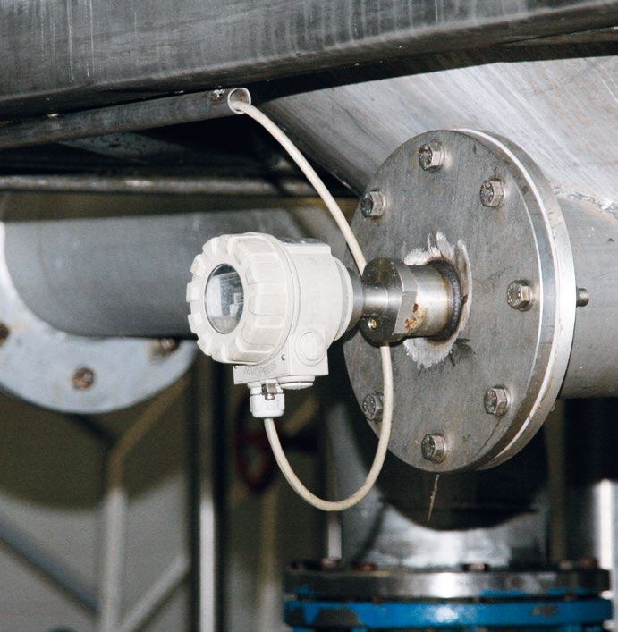
COM PA N Y PROFI LE                                                                                                                               2018

ESTEEMED PARTNER!

NIVELCO has established and maintained a leading and respected world market position, and in the past more than 3 and a half decades has sold almost
1 million units of level instrumentation. We are proud that NIVELCO is represented on the markets of many countries of the world through its subsidiaries
and distributors, and in a number of industrial segments our devices are used with satisfaction.

Our company is committed to establishing long-term, trusted and successful business relationships. We know
that besides getting an excellent value for your money, there are other key factors that matter to our clients
such as quality, guarantee and business reliability. This can only be provided through high performance,
quality products and services. In 2010, we introduced our 3-year full warranty for our products instead of the
previous 2-year warranty term. Thanks to the conscious quality policy that NIVELCO is committed to, our
quality indicators have shown excellent results and positive changes since then.

We are therefore pleased to announce that from 2018 onwards, instead of the present 3 years, uniquely
in the industry we provide 5 years of warranty for most of the NIVELCO instruments!

We are confident that our decision will further strengthen
the confidence in our company and our products.
                                                                                        Tamás Szőllős

                                    THE STORY OF A FAMILY VENTURE

                                    After training as an engineer in the “ITT Standard” telephone company, in 1939 Endre Szőllős started his
                                    own business designing and producing telephone systems for business and industry. While the World
                                    War II did not provide an easy period for Endre and his colleagues, the business grew and provided good
                                    training for his sons. Following their University courses in electrical engineering and economics respectively,
                                    Tamás and András Szőllős were able to lead the company forward, after the early death of Endre in 1969.
                                    By 1982, the production of a series of industrial controllers had led to a developing specialisation in level measurement
                                    and control: and NIVELCO was founded. In 1989, when International trade from
                                    Hungary became straightforward, NIVELCO had a full, proven level control
                                    product range and capability, backed by well established in-house manufacturing
                                    and engineering facilities. In 1989 the NIVELCO launch of the World’s first
                                    “Compact” ultrasonic level transmitter had a major impact, offering a combined
                                    sensor / transmitter in one unit, leading the world market.

NIVELCO took the opportunity offered by these newly available export markets, and opened trading relationships
with various identified distributors and sales agents. Building on existing sales links into neighbouring countries,
NIVELCO also invested in their own sales organisations and offices in Austria and Poland, and then later in the
Czech Republic, Romania and Russia. Our success in these ventures demonstrates that by maintaining our business
principles, expertise and specialist skills, NIVELCO can compete successfully with the best suppliers to the industry,
by providing:

■  Wide range of products to suit all applications
■  Investment in advanced technology expertise
     and high quality product development
■  High specification quality management and control
     systems
■  Worldwide marketing, sales and service support
■  Fast, flexible in-house production and customer
     order logistics
■  Company-wide IT System to provide full product
     design and production data
■  Fair, modest pricing, ensuring the capital for
     future customer support and development
■  Continuing investment in our people and their
     working relationships

Despite that in today’s globalised world, the multinational giants – set up for mass production – can rule the market, there are many medium-size companies
who specialise in satisfying customer needs, and manufacture products with high intellectual added value. The achievements of NIVELCO demonstrate that
flexible, customer-led medium-size companies can find their place in the market and maintain their independence.

                                                                                                                                                                5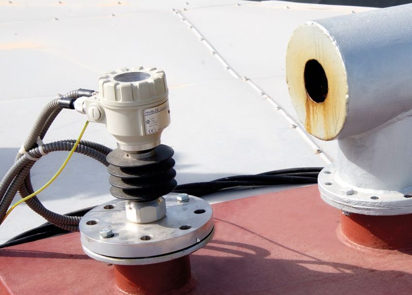
COM PA N Y PROFI LE                                                                                                                     2018

    NIVELCO’S TIMELINE

    1982   NIVELCO formed
    1982   NIVOSONAR – the first Ultrasonic level transmitter
    1984   NIVOCONT – Vibrating rod level switch
    1986   NIVOCAP – Capacitance level transmitter
           NIVOSONAR – Compact Ultrasonic level transmitter:
    1989
           A WORLD FIRST!
    1991   NIVELCO Messtechnik (Austria)
    1992   New factory opened in Budapest
    1994   NIVOPOINT – Float level switch
    1994   NIVOMAG – Magnetic coupling level switch
    1995   Accreditation to ISO 9001
           NIVELCO Company in Poland
    1996   NIVELCO Trade Center
           NIVOSWITCH – Vibrating fork level switch
    1999   NIVOPRESS – Hydrostatic level transmitter
    2000   Budapest Factory expansion
    2001   NIVOTRACK – Magnetostrictive level transmitter
    2002   Standardized mechanical and electronic construction
           HART® – Digital Communication in the transmitters
    2003   ATEX Hazardous Area Approvals
    2004   MultiCONT – he new system concept                     Efficient industrial production relies on the information provided by modern
           NIVELCO Bohemia (Czech Republic)                      high technology sensors and instrumentation. In the 1980’s the whole sensor
    2005   MicroTREK – Radar-based level transmitter             manufacturing industry was radically changed by developments in microprocessors
           NIVELCO T.M. Company in Romania                       and electronics. NIVELCO achieved the significant market position it holds today by
    2007   NIVELCO Instruments (India)                           recognising these developments.
    2007   NIVELCO Company in Russia
                                                                 Recognising the growth in the market demand, NIVELCO earned recognition primarily
    2008   NIVELCO Company in USA                                with its level transmitter, and gained a substantial global market share, based on its
    2009   AnaCONT – pH, ORP and conductivity transmitter        purposeful business policies and constant investment in technology.
           The first SIL product certification
    2010   AnaCONT – Dissolved oxygen transmitter                Year by year NIVELCO produced every 20th ultrasonic transmitter sold in the world,
    2012   PiloTREK – Non-contact radar level transmitter        every 50th vibration level switch, and every 100th radar level transmitter.
    2013   NIVOCAP CK – RF-capacitance level switch
                                                                 In this way NIVELCO has established and maintained a leading and respected
    2016   The first FM approval                                 world market position, and in the past 35 years has sold almost 1 million units of
    2017   EasyTREK SP-500                                       level instrumentation: NIVELCO is now one of the largest ultrasonic level transmitter
           UNICOMM HART®-USB / Bluetooth® modem                  producers in the world.

                                                                                                                                            2018

6
COM PA N Y PROFI LE                                                                                                                                  2018

THE HEADQUARTERS

From cramped beginnings in 1982, with 15 employees occupying 150 m2 in Budapest, NIVELCO has
invested in extensive facilities capable of total control of the production requirement. In the year 2000,
a further expansion to the new factory created a capacity of 10 000 m2, giving significant space for future
development: this is currently allocated to the NIVELCO Trade Center, and some associated activities.
In the currently unused factory areas, the NIVELCO Trade Center provides leased space to host headquarters
for other companies. NIVELCO engineering, manufacture and production is exclusively in Hungary: the
other subsidiaries deal only with sales and marketing activities, plus consulting, installation and service.
The modern air-conditioned factory and excellent working conditions ensure a neat and tidy environment,
and create the right conditions for producing good quality work.

                                    PRODUCTION

                                    NIVELCO has invested heavily in the best production machinery available, with all aspects of the required production
                                    being undertaken in the factory. Here, computer-controlled CNC machining centres, as well as surface mount electronics
                                    production facilities and fume extraction, make a clean and efficient unit. The investment is driven using a global IT system
                                    for production control and logistics. In this way NIVELCO maintains total control over the build, and has achieved quality
                                    management system approval to ISO9001. All production output is tested using automatic systems, heat-soaked and
                                    cycled where needed in special test chambers.

SALES AND SUPPORT                                                                      MARKETING

                                         Efficient technical sales support to cus-     The marketing department at the Hungarian headquarters supplies
                                         tomers, contractors and distributors          all marketing materials such as brochures, advertisements and
                                         has always formed an essential part of        presentations, for the subsidiary companies to show the unified
                                         the NIVELCO business approach, and            NIVELCO corporate image. The marketing team coordinates the
                                         the application knowledge and experi-         constant updating of all information on the multilingual NIVELCO
                                         ence developed in the sales team is a         website and is also responsible for keeping up-to-date downloadable
                                         major business strength. Input from the       colour brochures, technical documentation, etc.
                                         NIVELCO sales team covering the five          The NIVELCO movie
                                         regions in Hungary, and the NIVELCO           (presented on the
                                         sales companies in Poland, the Czech          website) was shot
Republic, Romania, India and Russia, as well as that from export distributors and      by our own
sales agents, is treated as a valuable resource to be shared, and to guide product     NIVELCO
planning and development. To provide and present this experience to new sales          crew to
personnel, and distributors, NIVELCO produce articles for publication, plus appli-     present
cation notes and reference site information for presentation on the website, and in    the manu-
the NIVELCO Magazine published twice                                                   facturing
a year. Hands-on demonstrations are                                                    capability
encouraged, frequent training courses                                                  and the wide
in the Budapest training centre provide                                                application possibilities
customers, installers and staff from sales                                             of NIVELCO instruments.
distributors with hands-on experience.                                                 Other priority tasks for the marketing department involve participation in
The NIVELCO showroom provides a                                                        exhibitions and organisation of regular professional training courses for
permanent resource where equipment                                                     our sales partners and customers, presenting detailed knowledge and
can be demonstrated in action.                                                         information about the NIVELCO instruments.

                                                                                                                                                                    7
COM PA N Y PROFI LE 2018
EXPORT MARKETING
Doing some business with East Bloc countries was what we had as export in the 80’s, when NIVELCO was
formed: the East Bloc was still its old self and markets were closed. Nevertheless NIVELCO was an export
driven company, and almost a decade later, in 1990, we were able to show our muscles to the world for the
first time. This was the beginning of NIVELCO’s export success. Twenty years later, exporting more than
80% of its production, NIVELCO has now proved itself to be an export oriented company. Covering over
65 countries through our own subsidiary companies and through distributors, our products reach almost
all world markets. To aid distributors and our own subsidiaries, regular
training programmes are organised in order for their staff to keep up
with technology driving NIVELCO’s high tech instruments. Sales meetings
held annually provide a vehicle for information transfer and for an exchange
of ideas between people from all over the world. When our dealers participate in international exhibitions, they are supported
with operational models, exhibition accessories and experts. With the success seen with the NIVELCO non-European
subsidiaries (like USA, Russia and India), there is the strong intention to open further similar subsidiaries in the near future.
REFERENCES
IN ALL INDUSTRIES AND ALMOST EVERYWHERE IN THE WORLD! This phrase best describes the wide application
possibilities of NIVELCO instruments. Many references to NIVELCO installations and applications are quoted on the website
– tank contents measurement in food, pharmaceuticals and chemicals; environment protection applications; sump control in
wastewater systems, and flow monitoring in effluent channels are just some of those illustrated. ALMOST NO MATTER WHAT
IS TO BE MEASURED! No matter what level you need to measure – whether it is sewage in the USA, animal feed pellets
in Hungary, palm oil in Malaysia, cement, sand and building materials in Austria – trust NIVELCO instruments to do the job.
Palm oil (Malaysia)
Contsruction materials (Austria) Wastewater treatment (Poland) Animal food (Hungary) Sewage pump station (USA) Land reclamation (South Korea)
STATISTICS RESEARCH AND DEVELOPMENT
The NIVELCO story over the last more 12 Subsidiaries
Other The main profile of the Research and Devel-
than 35 years has been one of opment Department is the development of
Export
10
Domestic
8
consistent growth – growth in factory 6
all manufactured products and technologies
production output and sales value, including mechanics, hardware and soft-
4
2
growth in employees and in our business 0
2005 2006 2007 2008 2009 2010 2011 2012 2013 2014 2015 2016 ware. More importantly, the Development
resources. Achieving a 7-fold sales Team is responsible for designing new prod-
Sales (million EUR)
growth from an employee base growing ucts in accordance with customer needs,
3-fold, productivity has also more than and driving these into production. Besides the new developments there is also
250
Subsidiaries
At headquarter (other)
At headquarter (production)
200
doubled over the period, assisted by some 150 continuous modernisation and revamping of the existing well-known products as
EU subsidies for IT and technological 100
well as supporting and optimising the product line to achieve better and better
development. As a consequence of 50
product quality. Creating a wide product portfolio – wider than the competitors –
effective and purposeful management, to be able to provide suitable solutions to special market needs, it is necessary
2005 2006 2007 2008 2009 2010 2011 2012 2013 2014 2015 2016
the capital employed within the NIVELCO Employees (person) to undergo many official design approval procedures, such as are needed with
Group has gradually grown, and reached 14
Subsidiaries
ATEX, PED, or shipping approvals, or with measurement accuracy and perfor-
more than 12 million Euros in 2016. mance certi-fications like OIML, GOST, or SIL. In the course of these procedures,
Nivelco Hungary
12
10
8
close co-operation has been established between NIVELCO and the international
classification institutions (BKI, TÜV, DNV GL, BV, OMH, etc).
6
Australia,
New Zealand, 4
North America Africa
Domestic
Our policy and our essential goal is to design and launch high technology, carefully
4%
South America 5%
25% 2
6%
0
2005 2006 2007 2008 2009 2010 2011 2012 2013 2014 2015 2016
tested products into the market, products which can be easily manufactured, that
Asia
12%
Employed capital (million EUR) can have a fast delivery time, operate according to the customers needs, and
Europe, including Hungary, presents can be sold at a competitive price. Having extensive practical experience and
Europe
48%
Geographics split of sales in 2016
the major established market, with 73% professional knowledge, the engineering team at NIVELCO has established the
of sales. In terms of the product ranges, knowledge, structure and procedures to achieve this goal. NIVELCO maintains
the sales split for 2016 shows that close links with academia and suppliers to utilise
Analytics
Conductivity
Paddle 1%
1%
Capacitance 2%
2%
while ultrasonics still maintain a 30% the most advanced developments available.
Bypass indicator
Ultrasonic
Magnetic float tr. 1%
32%
3%
Magnetic float sw.
7%
Microwave
share of the total business, further new Strong working links have been established
products have established a solid market with the Budapest University of Technology and
Vibration rod 11%
8%
Others Vibration fork
presence, and already radar systems Economics and with the Óbuda University, and
8% Nivopress 11%
9%
Product split of sales in 2016 have achieved significant sales. with other academic institutions, which has led to
the recruitment of many well trained engineers.
8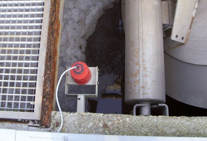
LE V EL TR A N SM I T TERS

GENERAL DESCRIPTION                                         NON- CONTAC T M ICROWAV E

                                                                                                                          LEVEL TRANSMITTERS
                                                            PiloTR EK
                                                                              ■■ 25 GHz (K-band) measuring signal
 Since its foundation NIVELCO has focused on the
                                                                              ■■ 2-wire compact transmitter
 manufacture of industrial level measurement                                  ■■ Accuracy up to ±3 mm
                                                                              ■■ Measuring range up to 23 m
 products. Our focus has not changed, demonstrated                            ■■ Max. 25 bar and 180 °C
                                                                              ■■ 4 – 20 mA + HART® communication
 by our wide level transmitter portfolio employing                            ■■ er > 1.9
                                                                              ■■ IP67 protection
 many different types of level measurement methods.                           ■■ Explosion-proof models

 Our ultrasonic level transmitter selection is definitely                                                   page 13

 the widest on the market offering integrated,              GUIDED M ICROWAV E
 compact, 2- or 4-wire transmitters for liquids or          M icroTR EK
                                                                              ■■ 2-wire compact transmitter
 solids with remarkable number of optional choices.                           ■■ TDR principle
                                                                              ■■ ±5 mm or ±20 mm accuracy
   The K-band PiloTREK non-contact level                                     ■■ er > 1.4
   transmitters are regarded the most progressive                             ■■ Measuring range up to 24 m
                                                                              ■■ 4 – 20 mA + HART® communication
   non-contact level transmitters of the industrial                           ■■ Max. 40 bar and +200 °C
                                                                              ■■ Rod or cable probes
   process automation field.                                                  ■■ Plug-in graphic display module
                                                                              ■■ Explosion-proof models
   The high-precision NIVOTRACK magnetostrictive                                                           page 23

   level transmitters with 0.1 mm resolution are            C A PACITA NCE LE V EL TR A NSM IT TERS
                                                            N I VOC A P
   applicable for custody transfer liquid level
                                                                              ■■ 2-wire compact transmitter
   measurements.                                                              ■■ Rod or cable probes up to 20 m
                                                                              ■■ er > 1.5
   The NIVOFLIP bypass liquid level indicators are                           ■■ Fully or partly insulated probes
                                                                              ■■ 32-point linearization
   suitable for high temperature applications and                             ■■ High sensitivity
                                                                              ■■ 4 – 20 mA + HART® communication
   high pressure processes.
                                                                              ■■ Explosion-proof models
   The NIVOCAP capacitance level transmitters
                                                                                                            page 29
   provides highly reliable measurement thanks to
                                                            H YDROS TATIC LE V EL TR A NSM IT TERS
   the well-know and accepted capacitive principle.
                                                            N I VOPR ES S D
 Most of our transmitters are available in PFA coated
                                                                              ■■ 2-wire compact level and
 version for aggressive mediums, and all transmitter                            pressure transmitter
                                                                              ■■ -1 bar – 400 bar
 families have explosion-proof models applicable in                           ■■ High overload capability
                                                                              ■■ Accuracy: 0.25%
 hazardous environments.                                                      ■■ Stainless steel diaphragm
                                                                              ■■ Plug-in display module
                                                                              ■■ 4 – 20 mA + HART® communication
                                                                              ■■ Explosion-proof models

                                                                                                            page 34

                                                                                                                      9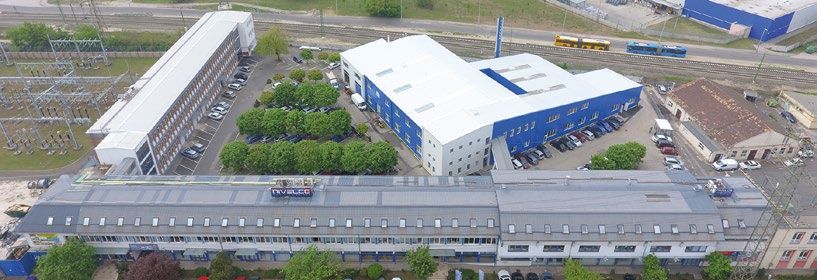
LE V EL TR A N SM I T TERS

                          H YDROS TATIC LE V EL TR A NSM IT TERS                                ULTR A SONIC INTEGR ATED
LEVEL TRANSMITTERS

                          N I VOPR ES S N                                                       Eas yTR EK FOR LIQUI DS
                                              ■■ 2 or 3-wire submersible transmitter                            ■■ For liquid level measurement
                                              ■■ Stainless steel or fully plastic body                          ■■ 2-wire integrated transmitter
                                              ■■ Up to 200 m range                                              ■■ Narrow 5° beam angle
                                              ■■ 4 – 20 mA + HART® communication                                ■■ Max. 25 m measurement range
                                              ■■ Linearity error: 0.25 %                                        ■■ PP, PVDF, PTFE transducers
                                              ■■ Incorporated Pt100 temperature sensor                          ■■ 32-point linearization
                                              ■■ Venting tube in cable                                          ■■ 4 – 20 mA + HART® communication
                                              ■■ IP68 protection                                                ■■ Open channel flow metering
                                              ■■ Explosion-proof models                                         ■■ Explosion-proof models, IP68

                                                                                page 37                                                      page 54

                          M AGNE TOS TR IC TI V E TR A NSM IT TERS                              ULTR A SONIC COM PAC T
                          N I VOTR ACK                                                          EchoTR EK FOR LIQUI DS
                                              ■■ 2-wire compact and                                             ■■ For liquid level measurement
                                                 mini compact transmitter                                       ■■ 2- and 4- wire compact transmitter
                                              ■■ 0.1 mm or 1 mm resolution                                      ■■ Narrow 5° beam angle
                                              ■■ Max. 15 m measurement range                                    ■■ Max. 25 m measurement range
                                              ■■ For liquids with min. 0.4 kg/dm3 density                       ■■ PP, PVDF, PTFE and s.s. transducers
                                              ■■ Distance, level and volume measurement                         ■■ 32-point linearization
                                              ■■ Rigid or flexible probes                                       ■■ Plug-in display module
                                              ■■ OIML R-85 international certification                          ■■ 4 – 20 mA + HART® communication
                                              ■■ Explosion-proof models                                         ■■ Explosion-proof models, IP67

                                                                                page 43                                                      page 61

                          BYPA S S LE V EL INDIC ATORS                                          ULTR A SONIC INTEGR ATED
                          N I VOFLI P                                                           Eas yTR EK FOR SOLI DS
                                              ■■ Operation without power supply                                 ■■ For free flowing solid measurement
                                              ■■ 500 – 5500 mm measuring range                                  ■■ 4-wire integrated transmitter
                                              ■■ ±10 mm accuracy                                                ■■ Narrow 5° beam angle
                                              ■■ Stainless steel or titan float                                 ■■ Max. 60 m measurement range
                                              ■■ Optional strap-on level switches                               ■■ PP and aluminium sensors
                                              ■■ Max. 100 bar process pressure                                  ■■ Joystick aiming device
                                              ■■ DIN and ANSI flanges                                           ■■ 4 – 20 mA + HART® communication
                                              ■■ High temp. version up to +250 °C                               ■■ Explosion-proof models, IP6X
                                              ■■ PED approval

                                                                                page 49                                                      page 70

                          SET-UP AND CONFIG SOFTWARE                                            ULTR A SONIC COM PAC T
                          E V iew2                                                              EchoTR EK FOR SOLI DS
                                              ■■ Configuration and calibration software                         ■■ For free flowing solid measurement
                                                 for up to 15 transmitters                                      ■■ 4-wire compact transmitter
                                              ■■ Downloadable free of charge                                    ■■ Narrow 5° beam angle
                                              ■■ Remote programming tool for all HART                           ■■ Max. 60 m measurement range
                                                 capable NIVELCO level, temperature,                            ■■ PP and aluminium sensors
                                                 pressure and liquid analytical transmitters                    ■■ Joystick aiming device
                                              ■■ Query, edit, load & save                                       ■■ Plug-in display module
                                                 transmitter parameters                                         ■■ 4 – 20 mA + HART® communication
                                              ■■ Limited trend monitoring capability                            ■■ Explosion-proof models, IP6X
                                              ■■ Easy editing for linearisation table entries
                                                                                                                                             page 73

                     10
A PPLIC ATION S
11
LEVEL TRANSMITTERSLEVEL TRANSMITTERS
12
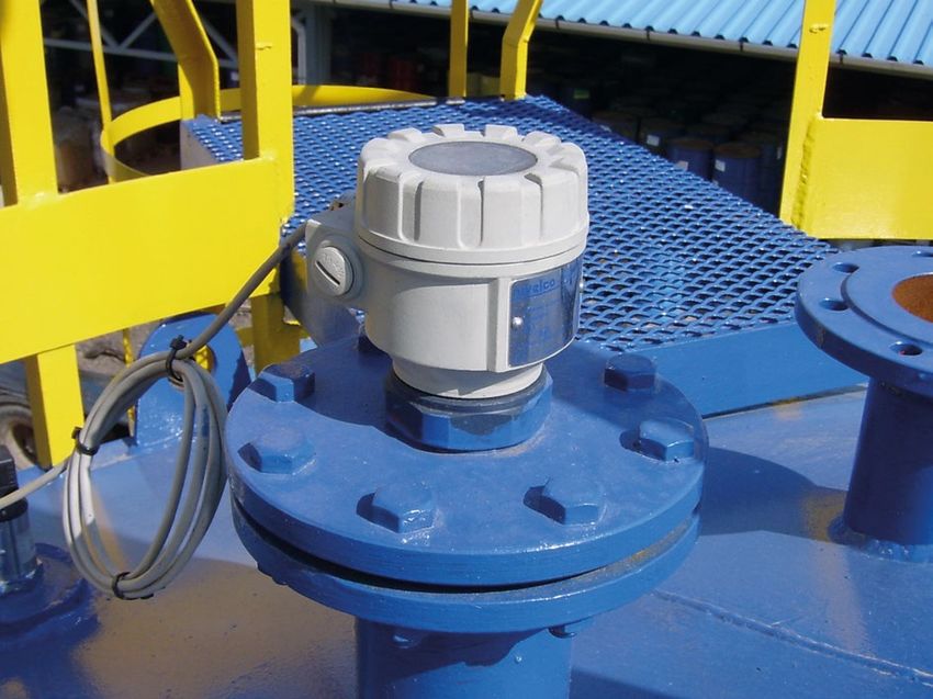
A PPLIC ATION SNON - CON TAC T M ICROWAV E LE V EL TR A N SM I T TERSPiloTR EK
GENERAL DESCRIPTION
LEVEL TRANSMITTERS
The 25 GHz (K-band) PiloTREK Pulse Radars are regarded as the most progressive non-contact level transmitters of the industrial process automation field. Their accuracies are excellent
and their short and narrow antennas make their installation simple and low cost. NIVELCO’s K-band radar featuring ±3 mm accuracy and short dead band excels with its versatile housing
concept lining up plastic, aluminium and stainless steel versions. Its antenna range incorporates stainless steel horn or parabolic antenna and enclosed plastic tube varieties. The enclosed
antenna versions can be replaced without removing the antenna enclosure from the process. Local programming of the PiloTREK is aided by a plug-in display module. If on-site reading
is not desired this module may not be required thus reducing cost of ownership. The signal processing algorithm of the PiloTREK is based on NIVELCO’s 30 years of experience with non-
contact level measurement making it an excellent choice for applications simple and challenging alike.
MAIN FEATURES
■■ 2-wire K-band Pulse Burst Radar
■■ 25 GHz frequency
■■ Max. 23 m measuring range for liquids and slurries
■■ ±3 mm accuracy
■■ Easy installation due to small antennas
■■ Parabolic, horn and enclosed antenna types
■■ IP68 rated integrated type
■■ Sanitary types for meeting high hygienic requirements
■■ High temperature version
■■ Plug-in graphical display module
■■ Explosion proof version
WGS-150-C Ex
INDUSTRY WES-140
SEGMENTS CERTIFICATIONS
■■ Water, wastewater ■■ ATEX approved (Ex ia)
■■ Power generation ■■ IEC approved (Ex ia)
■■ Food and beverage ■■ FM & CSA approved
■■ Pharmaceutical
■■ Chemical
WPP-140
APPLICATION
■■ Liquids and slurries in general
WGK-150
OPERATION
The operation of the non-contact microwave level transmitters is based on the measurement of the time of flight of the microwave burst. The propagation speed of
microwave impulses is practically the same in air, gases and in vacuum, independently from the process temperature and pressure, so the measured distance is not affected
by the physical parameters of medium to be measured. The level transmitter induces microwave impulses a few nanosecond long in the antenna and a part of the energy
of the emitted signals is bounced (reflected) back from the measurement surface depending on the measured media. The time of flight of the reflected signal is measured and
processed by the electronics, and then this is converted to distance, level or volume proportional data. The measurability of the level of a specific medium is depending on the signal
strength of the reflected microwave impulses. The signal strength of the reflected impulses is considerably depending on the distance to be measured, the relative dielectric constant
of the measured medium and the turbulence of the surface. The relative dielectric constant (εr) of the medium should be more than 1.4 in case of parabolic design, or it should be
more than 1.9 with horn antenna types.
ANTENNA TYPES
Antenna diameter
DN40 (1½") DN50 (2") DN80 (3") DN150 (6")
Antenna type
Process connection
1½" BSP/NPT 2" TRICLAMP DN50 MILCH 2" BSP/NPT DN80 – DN150 flanges
Stainless steel (1.4571 / 316 Ti) horn
Plastic (PP) enclosure
Plastic (PTFE) enclosure
Stainless steel (1.4571 / 316 Ti) parabolic
13NON - CON TAC T M ICROWAV E LE V EL TR A N SM I T TERS PiloTR EK
TECHNICAL DATA
LEVEL TRANSMITTERS
Compact
Type Integrated
Plastic housing Metal housing High temperature version
Measured values Level, Distance; Calculated values: Volume, Mass
Frequency of the measurement signal ~25 GHz (K-band)
Measuring range 0.2 m – 23 m (depending on the antenna type - see: special data of the antenna variations)
< 0.5 m: ±25 mm; 0.5 m – 1 m: ±15 mm; 1 m – 1.5 m: ±10 mm;
Linearity error (1)
1.5 m – 8 m: ±3 mm; > 8 m: ±0.04% of the measured distance
Minimum beam angle 11° (depending on the antenna type) 6° (depending on the antenna type; see: special data of the antenna variations)
Minimum er of the medium 1.9 (depending on the meas. range) 1.4 (depending on the meas. range; see: max. measurement range vs. er diagram)
Resolution 1 mm
Temperature error (as per EN 61298-3) 0.05% FSK / 10 °C (-20 °C … +60 °C)
Power supply 20 V – 36 V DC
Digital communication 4 – 20 mA + HART®
Output
Display – SAP-300 graphical display unit
Measuring frequency 10 – 60 sec as per the application settings
Antenna diameter 38 mm (1½"), 48 mm (2"), 75 mm (3"), 148 mm (6")
Horn: 1.4571 (316 Ti) stainless steel; Horn, Parabolic: 1.4571 (316 Ti) stainless Horn, Parabolic: 1.4571 (316 Ti);
Antenna material
enclosure: PP, PTFE steel; enclosure: PP, PTFE enclosure: PTFE
-30 ºC … +100 ºC, (up to 120 ºC for max. 2 min)
Process temperature -30 ºC … +180 ºC
with PP antenna enclosure: max.: 80 ºC
Max. process pressure 25 bar at 120 ºC; with plastic antenna enclosure: 3 bar at 25 ºC
Ambient temperature -20 ºC … +60 ºC
Process connection Threaded, Flanged or Sanitary connections (as per order codes)
Ingress protection IP68 IP67
LiYCY type. 2x 0.5 mm2
shielded Ø 6 mm cable; 2x M20 x1.5 cable glands + internal thread for 2x ½" NPT cable protective pipe,
Electrical connection standard cable length: cable outer diameter: Ø7 – Ø13 mm, wire cross section: max. 1.5 mm2
5 m (can be ordered up to 30 m)
Electrical protection Class III
Housing material Plastic (PP) Plastic (PBT) Paint coated aluminium or Stainless steel
Sealing Viton, EPDM
Communication certifications R&TTE, FCC
Aluminium: 2 – 2.6 kg Aluminium: 2.7 – 3.3 kg
Mass 1 – 1.6 kg
St. steel: 3.3 – 3.9 kg Stainless steel: 4 – 4.6 kg
(1) Under reference conditions of reflection and stabilized temperature
SPECIAL DATA FOR Ex CERTIFIED MODELS
Plastic housing, Plastic housing, Metal housing High temperature version
Type integrated compact W S-1 - with metal housing
WPM-1 - W M-1 - W K-1 - WH -1 - , WJ -1 -
Protection type Intrinsically safe
Ex ia IIB T6 … T4 Ga Ex ia IIIC Ex ia IIB T6 … T3 Ga Ex ia IIIC
IEC Ex Ex ia IIB T6 … T5 Ga Ex ia IIB T6 … T5 Ga/Gb T85 °C … T110 °C Da/Db Ex ta/tb IIIC T85 °C … T180 °C Da/Db Ex ta/tb IIIC
T85 °C … T110 °C Da/Db T85 °C … T180 °C Da/Db
Ex marking x II 1G Ex ia IIB T6 … T4 Ga x II 1G Ex ia IIB T6 … T3 Ga
x II 1/2 D Ex ia IIIC x II 1/2 D Ex ia IIIC
x II 1 G Ex ia IIB x II 1/2 G Ex ia
ATEX T85 °C … T110 °C Da/Db T85 °C … T180 °C Da/Db
T6 … T5 Ga IIB T6 … T5 Ga/Gb
x II 1/2 D Ex ta/tb IIIC x II 1/2 D Ex ta/tb IIIC
T85 °C … T110 °C Da/Db T85 °C … T180 °C Da/Db
Ui = 30 V,
Intrinsically safe data Ii = 140 mA, Pi = 1 W, Ui = 30 V, Ii = 140 mA, Pi = 1 W, Ci 16 nF, Li 200 μH
Ci 30 nF, Li 200 μH
Power supply 20 – 30 V DC
Ambient temperature -20 °C … +60 °C
In case of WPM type: LiYCY
type. 2x 0.5 mm2 shielded
2x M20 x1.5 metal cable glands, cable outer diameter: Ø7 – Ø13 mm,
Electrical connection Ø6 mm cable; standard cable
wire cross section: max. 1.5 mm2
length: 5 m (can be ordered
up to 30 m)
14NON - CON TAC T M ICROWAV E LE V EL TR A N SM I T TERS PiloTR EK
SPECIAL DATA OF THE ANTENNA VARIATIONS
LEVEL TRANSMITTERS
WM/WS/ WM/WS/ WM/WS/ WM/WS
Type
WK-14 WK-15 WK-18 WK-11
DN40 (1½") s. steel DN50 (2") s. steel DN80 (3") stainless steel DN150 (6") s. steel
Name
horn antenna horn antenna horn antenna with flange parabolic antenna
Process connection 1½" BSP, 1½" NPT 2" BSP, 2" NPT DN80 – DN150 flanges DN150 flange
Material of wetted parts 1.4571 (316 Ti), PTFE; in case of WPM: 1.4571 (316 Ti), PTFE, PP 1.4571 (316 Ti), PTFE
Beam angle 19° 16° 11° 6°
Dead zone 0.2 m 0.4 m
WM / WS / WK-14 WM / WS / WK-14
Type WP-14 WP-15
+ WAT-14T-0 + WAT-14R-0
DN40 (1½") PP or PTFE Sanitary type DN40 (1½") horn antenna DN50 (2") PP or PTFE
Name
encapsulated antenna with PTFE antenna enclosure encapsulated antenna
Housing Plastic Plastic / Paint coated aluminium / Stainless steel Plastic
Process connection 1½" BSP, 1½" NPT 2" TRICLAMP DN50 MILCH 2" BSP, 2" NPT
Material of wetted parts PP or PTFE 1.4571 (316 Ti), PTFE PP or PTFE
Dead zone 0.3 m
(1) Under
reference conditions of reflection (as per EN 61298-3, moreover in case of interference-free environment, from min. 10 m2 target surface)
and stabilized temperature. The plastic antenna enclosures result 10% (PTFE) or 20% (PP) decrease in the maximal measurement range!
(2) In some instances (e.g. disturbing reflections, steam or gas condensation, EMC noises) the maximal measurement range might decrease by 50% !
(3) Dielectric constant (εr) of liquids used in storage tanks with flat liquid surface
(4) Dielectric constant (εr) of liquids used in process tanks or where liquid surface is waving
POLARIZATION BACKGROUND MAPPING
The PiloTREK non-contact level transmitters emit linearly polarized microwave The background mapping feature provides excellent solution to ignore unwanted
impulses. The polarization plane of the emitted impulses can be rotated fully in case of false reflections coming from (not-moving) disturbing objects. For this purpose the
W S, W M and the W K types. The rotation of the polarization plane can minimize instrument needs to map the totally empty tank to create a ”background image”.
unwanted false reflections from disturbing objects or from the tank wall. The orientation of Then the measurement evaluation software of PiloTREK will automatically recognise
the polarization plane coincides with the line drawn between the cable glands. and ignore the false reflections coming from the disturbing objects inside the tank.
15NON - CON TAC T M ICROWAV E LE V EL TR A N SM I T TERS PiloTR EK
TEMPERATURE DATA FOR EX CERTIFIED MODELS
LEVEL TRANSMITTERS
Hazardous gas atmospheres Explosive dust atmospheres
Plastic housing Metal housing
W S-1 - High temperature High temperature
W M-1 - W K-1 - W S-1 -
W P-1 - WH - 1 - WH -1 - W K-1 - WH -1 -
WJ - 1 - WJ -1 - WJ -1 -
Ex ia IIB Ex ia IIB Ex ia IIIC, Ex ta/tb IIIC
Max.
permissible
medium temp. +80 °C +95 °C +80 °C +95 °C +100 °C +130 °C +180 °C +80 °C +95 °C +100 °C +180 °C
at the antenna
(min.: -30 °C)
Temp.
T6 T5 T6 T5 T4 T4 T3 T85 °C T100 °C T110 °C T180 °C
classes
SPECIAL DATA FOR FM CERTIFIED MODELS
Type WS-1-A WS-1-B
US (XP-IS) Class I Div 1 Gas Groups C & D T6 (NI) Class I Div 2 Gas Groups C & D T6
Marking
Canada (XP-IS) Class I Div 1 Gas Groups C & D T6 (NI) Class I Div 2 Gas Groups C & D T6
Suitable for Class I Division 1 Groups C or D
Class I Division 2 Groups C or D
hazardous locations Class I Division 2 Groups C or D
Electrical connection NPT ½" conduit entry; plug-in type terminal blocks for 0.75 to 1.5 mm2 wire cross section
TEMPERATURE DATA FOR FM CERTIFIED MODELS
Maximum allowed ambient temperatures over medium temperatures
Maximum allowed
Maximum
Temperature code Process temperature ambient
resulting surface Model variant restriction
(TC) (Pt) max temperature
temperature
at the enclosure
t6
-30 °C … +100 °C (1)
+60 °C +76 °C –
(through T1)
For medium temperatures above +100 °C use
T6
-30 °C … +180 °C (1)
+60 °C +76 °C High Temperature transmitters
(through T1)
WHS-1 - or WJS-1 -
(1) For technological safety, the process temperature shall always be chosen in accordance with the autoignition temperature of the measured medium.
WIRING
Brown 4 – 20 mA current
output and power
White supply (HART®)
Display
Green module
Loop current connector
measuring
Yellow
Loop current
Green-Yellow Ground measuring
connector
2 5
4 – 20 mA current
output and power
supply (HART®)
3 4
- +
16NON - CON TAC T M ICROWAV E LE V EL TR A N SM I T TERS PiloTR EK
WIRING FOR CLASS I DIV 2 WIRING FOR CLASS I DIV 1
LEVEL TRANSMITTERS
RATED DEVICES RATED DEVICES
Electrical data: Maximal allowed input voltage:
Ci 16 nF Li 0.2 mH Ii 22 mA Ui 35 V DC Umax = 35 V DC Um = 250 V
Earth Earth
Max. 35 V DC
Earth Earth
Earth Earth
PROGRAMMING, ECHO MAP
With the help of the SAP-300 plug-in display a simplified full-parameter programming can be
accomplished, the parameters of measurement and output can be set using the text-based menu system.
The large LCD dot-matrix display displays the measured values in numerical and bar graph form. The Echo
Map feature helps to detect false reflections and aids the optimization of the measurement configuration.
MOUNTING
To avoid unwanted multiple reflections the instrument should not be mounted in the middle of the tank or in the vicinity of the filling place or the
outlet of the tank. The ideal position for the PiloTREK is on the r = (0.3 – 0.5) R in case of cylindrical tank. The distance between the sensor
and the tank wall should be at least 200 mm. The mounting placement should be as far as possible from the disturbing objects inside the tank
and from the sources of disturbing effects such as waving, vortex or strong vibrations. The antenna face should be parallel to the medium surface
within ±2 – 3°. To avoid overheating the instrument should be protected against direct sunshine.
PiloTREK TRANSMITTERS IN SYSTEM WITH A PC WHS-18
The instruments with HART® output can be connected to a PC using a UNICOMM HART-USB modem. Max. 15 normal (non-Ex) instruments
can be connected to a single HART® loop. All measured values can be visualized and/or the instruments can be remote programmed via
digital HART® communication. Applicable software: EView2 configuration software or NIVISION process visualization software.
HART
PiloTREK TRANSMITTERS IN HART MULTIDROP LOOP
The MultiCONT can handle digital data coming from HART® capable NIVELCO transmitters (e.g. level, temperature, pressure, pH, dissolved oxygen, etc.). The digital (HART®)
information is processed, displayed and transmitted via RS485 communication line to a PC when needed. Remote programming of the transmitters is also possible. Visualisation
on PC can be accomplished with NIVISION process visualisation software.
WES-119
HART® RS485
WHS-140 + WAT-14T
17NON - CON TAC T M ICROWAV E LE V EL TR A N SM I T TERS PiloTR EK
PiloTREK WP-100 5 years
LEVEL TRANSMITTERS
2-wire integrated compact pulse burst radar level transmitter for liquids
with DN40, DN50 stainless steel horn antenna or plastic encapsulated antenna
Version
W n – 1 nn – n
P Integrated transmitter
Antenna / Housing
W P – 1 nn – n
P * PP / PP
M 1.4571 / PP
* Ex version not available
Antenna / Connection size
W P n – 1 n – n
4 Horn DN40 / 1 1/2"
5 Horn DN50 / 2"
Process connection
W P n – 1 n – n WPM-140 / 14N
0 BSP
N NPT
Output / Approval
W P n – 1 nn –
4 4-20 mA + HART
8 4-20 mA + HART / Ex ia
Cable
Maximum length 30 m; each started 1 m over the standard 5 m
Accessories to order (see relevant page for details)
S A T – 3 0 4 – 0 HART-USB modem
S A T – 5 0 4 – n
S A K – 3 0 5 – 2 HART-USB/RS485 modem
S A K – 3 0 5 – 6 HART-USB/RS485 modem / Ex ia
S A S – 3 0 3 – 0 EView2 software package
Antenna enclosures
W A P – 1 4 0 – 0 *** PP enclosure with 1 1/2" BSP process connection for DN40 antenna
W A P – 1 4 N – 0 *** PP enclosure with 1 1/2" NPT process connection for DN40 antenna
W A T – 1 4 0 – 0 *** PTFE enclosure with 1 1/2" BSP process connection for DN40 antenna
W A T – 1 4 N – 0 *** PTFE enclosure with 1 1/2" NPT process connection for DN40 antenna
W A P – 1 5 0 – 0 *** PP enclosure with 2" BSP process connection for DN50 antenna WPP-140 / 14N
W A P – 1 5 N – 0 *** PP enclosure with 2" NPT process connection for DN50 antenna
W A T – 1 5 0 – 0 *** PTFE enclosure with 2" BSP process connection for DN50 antenna
W A T – 1 5 N – 0 *** PTFE enclosure with 2" NPT process connection for DN50 antenna
W A T – 1 4 T – 0 *** PTFE enclosure with 2" TriClamp 1.4571 process connection for DN40 antenna
PTFE enclosure with DN50 Pipe coupling 1.4571 process connection for DN40
WA T – 1 4 R – 0 ***
antenna
*** To be ordered together with the transmitter, Ex version not available
WPP-150 / 15N
18NON - CON TAC T M ICROWAV E LE V EL TR A N SM I T TERS PiloTR EK
PiloTREK WP-100 5 years
LEVEL TRANSMITTERS
2-wire integrated compact pulse burst radar level transmitter for liquids
with DN80 stainless steel horn antenna or plastic encapsulated antenna
Version
W M – 1 8 n – n
P Integrated transmitter
Antenna / Housing
W P – 1 8 n – n
M 1.4571 / PP
Antenna / Connection size
W P M – 1 n – n As per
8 Horn DN80 / Flange order code
Process connection
W P M – 1 8 – n
2 DN80 PN25 1.4571 flange
3 DN100 PN25 1.4571 flange
6 DN80 PP flange drilled like PN25
7 DN100 PP flange drilled like PN25
A 3" RF 150 psi 1.4571 flange
B 4" RF 150 psi 1.4571 flange
E 3" FF PP flange drilled like 150 psi
F 4" FF PP flange drilled like 150 psi
J JIS 10K 80A 1.4571 flange
K JIS 10K 100A 1.4571 flange
P JIS 80A PP flange drilled like 10K WPM-18
R JIS 100A PP flange drilled like 10K
Output / Approval
W P M – 1 8 n –
4 4-20 mA + HART
8 4-20 mA + HART / Ex ia
Cable
Maximum length 30 m; each started 1 m over the standard 5 m
Accessories to order (see relevant page for details)
S A T – 3 0 4 – 0 HART-USB modem
S A T – 5 0 4 – n
S A K – 3 0 5 – 2 HART-USB/RS485 modem
S A K – 3 0 5 – 6 HART-USB/RS485 modem / Ex ia
19NON - CON TAC T M ICROWAV E LE V EL TR A N SM I T TERS PiloTR EK
PiloTREK W-100 5 years
LEVEL TRANSMITTERS
2-wire compact radar level transmitter for liquids
with DN40, DN50 stainless steel horn antenna or plastic encapsulated antenna
Version
W n – 1 nn – n
E Transmitter
G Transmitter with LCD display
H * High temperature transmitter (max. 180°C)
J * High temperature transmitter with LCD display (max. 180°C)
* High temperature version can be ordered only with aluminium housing
Antenna / Housing
Wn – 1 nn – n
P ** PP / Plastic, PBT, glass fibre reinforced
M 1.4571 / Plastic, PBT, glass fibre reinforced WES-140 / 14N
S 1.4571 / Aluminium (paint coated)
K 1.4571 / Stainless steel
** Ex version not available
Antenna / Connection size
Wnn – 1 n – n
4 Horn DN40 / 1 1/2"
5 Horn DN50 / 2"
Process connection
Wnn – 1 n – n
0 BSP
N NPT
Output / Approval / El. connection
Wnn – 1 nn –
4 4-20 mA + HART
8 4-20 mA + HART / Ex ia WEP-140 / 14N
A **** 4-20 mA + HART / XP IS DIV1 / 1/2" NPT / Dual compartment
C **** 4-20 mA + HART / Ex d [ia] / M20x1.5 / Dual compartment
**** Only with aluminium housing
Need of IEC is to be specified with order
Accessories to order (see relevant page for details)
S A P – 3 0 0 – 0 Graphic plug-in display module
S A T – 3 0 4 – 0 HART-USB modem
S A T – 5 0 4 – n
S A K – 3 0 5 – 2 HART-USB/RS485 modem
S A K – 3 0 5 – 6 HART-USB/RS485 modem / Ex ia
Antenna enclosures
W A P – 1 4 0 – 0 *** PP enclosure with 1 1/2" BSP process connection for DN40 antenna
W A P – 1 4 N – 0 *** PP enclosure with 1 1/2" NPT process connection for DN40 antenna
W A T – 1 4 0 – 0 *** PTFE enclosure with 1 1/2" BSP process connection for DN40 antenna
W A T – 1 4 N – 0 *** PTFE enclosure with 1 1/2" NPT process connection for DN40 antenna
W A P – 1 5 0 – 0 *** PP enclosure with 2" BSP process connection for DN50 antenna
W A P – 1 5 N – 0 *** PP enclosure with 2" NPT process connection for DN50 antenna
W A T – 1 5 0 – 0 *** PTFE enclosure with 2" BSP process connection for DN50 antenna WHS-140 + WAT-14T
W A T – 1 5 N – 0 *** PTFE enclosure with 2" NPT process connection for DN50 antenna
W A T – 1 4 T – 0 *** PTFE enclosure with 2" TriClamp 1.4571 process connection for DN40 antenna
PTFE enclosure with DN50 Pipe coupling 1.4571 process connection for DN40
WA T – 1 4 R – 0 ***
antenna
*** To be ordered together with the transmitter, Ex version not available
WES-140-C, WGS-140-C
WES-14N-C, WGS-14N-C
20NON - CON TAC T M ICROWAV E LE V EL TR A N SM I T TERS PiloTR EK
PiloTREK W-100 5 years
LEVEL TRANSMITTERS
2-wire compact radar level transmitter for liquids
with DN80 stainless steel horn antenna or plastic encapsulated antenna
Version
W n – 1 8 n – n
E Transmitter
G Transmitter with LCD display
H * High temperature transmitter (max. 180°C)
J * High temperature transmitter with LCD display (max. 180°C) As per
order code
* High temperature version can be ordered only with aluminium housing
Antenna / Housing
Wn – 1 8 n – n
M 1.4571 / Plastic, PBT, glass fibre reinforced
S 1.4571 / Aluminium (paint coated)
K 1.4571 / Stainless steel
Antenna / Connection size
Wnn – 1 n – n
8 Horn DN80 / Flange
Process connection WES-18
Wnn – 1 8 – n
2 DN80 PN25 1.4571 flange
3 DN100 PN25 1.4571 flange
5 DN150 PN25 1.4571 flange
6 DN80 PP flange drilled like PN25
7 DN100 PP flange drilled like PN25
A 3" RF 150 psi 1.4571 flange
B 4" RF 150 psi 1.4571 flange
E 3" FF PP flange drilled like 150 psi
F 4" FF PP flange drilled like 150 psi
J JIS 10K 80A 1.4571 flange As per
K JIS 10K 100A 1.4571 flange order code
P JIS 80A PP flange drilled like 10K
R JIS 100A PP flange drilled like 10K
Output / Approval / El. connection
Wnn – 1 8 n –
4 4-20 mA + HART
8 4-20 mA + HART / Ex ia
A ** 4-20 mA + HART / XP IS DIV1 / 1/2" NPT / Dual compartment
C ** 4-20 mA + HART / Ex d (ia) / M20x1.5 / Dual compartment
** Only with aluminium housing
Accessories to order (see relevant page for details) WEK-18
S A P – 3 0 0 – 0 Graphic plug-in display module
S A T – 3 0 4 – 0 HART-USB modem
S A T – 5 0 4 – n
S A K – 3 0 5 – 2 HART-USB/RS485 modem
S A K – 3 0 5 – 6 HART-USB/RS485 modem / Ex ia
As per
order code
WHS-18
21NON - CON TAC T M ICROWAV E LE V EL TR A N SM I T TERS PiloTR EK
PiloTREK W-100 with parabolic antenna 5 years
LEVEL TRANSMITTERS
2-wire compact radar level transmitter for liquids
with stainless steel parabolic antenna
Version
W n – 1 1 n – n
E Transmitter
G Transmitter with LCD display
H * High temperature transmitter (max. 180°C)
J * High temperature transmitter with LCD display (max. 180°C)
* High temperature version can be ordered with metal housing and metal flange only
Antenna / Housing
Wn – 1 1 n – n
M 1.4571 / Plastic, PBT, glass fibre reinforced
S 1.4571 / Aluminium (paint coated)
WES-115
K 1.4571 / Stainless steel
Antenna / Connection size
Wnn – 1 n – n
1 Parabolic DN150 / with flange
Process connection
Wnn – 1 1 – n
5 DN150 PN25 1.4571 flange
9 DN150 PP flange drilled like PN25
D 6" RF 150 psi 1.4571 flange
H 6" FF PP flange drilled like 150 psi
M JIS 10K 150A 1.4571 flange
T JIS 150A PP flange drilled like 10K
Output / Approval / El. connection
Wnn – 1 1 n –
4 4-20 mA + HART
8 4-20 mA + HART / Ex ia
A ** 4-20 mA + HART / XP IS DIV1 / 1/2" NPT / Dual compartment
C ** 4-20 mA + HART / Ex d (ia) / M20x1.5 / Dual compartment
** Only with aluminium housing
WEK-115
Accessories to order (see relevant page for details)
S A P – 3 0 0 – 0 Graphic plug-in display module
S A T – 3 0 4 – 0 HART-USB modem
S A T – 5 0 4 – n
S A K – 3 0 5 – 2 HART-USB/RS485 modem
S A K – 3 0 5 – 6 HART-USB/RS485 modem / Ex ia
WHS-115
22GUI DED M ICROWAV E LE V EL TR A N SM I T TERS M icroTR EK
GENERAL DESCRIPTION
LEVEL TRANSMITTERS
The MicroTREK Guided Wave Radar level transmitter is designed for continuous level measuring of conductive or non-conductive
liquids, pulps and solids. MicroTREK level gauge operates based on the well-known TDR (Time Domain Reflectometry) principle.
Micropulses are sent along a probe guide at the speed of light. As soon as the impulse reaches the surface of the medium, it is
reflected back to the electronic module. Level distance is directly proportional to the flight time of the impulse.
The reflected signal is dependent on the dielectric constant of the material, the feasibility of the measurement is er ≥ 1.4.
The TDR technology is unaffected by the properties of the medium as well as that of the space above it. Measurement is also
unaffected by the change in the physical properties of the materials such as temperature, pressure, dielectric constant.
MAIN FEATURES
■■ Measuring range up to 24 m
■■ Accuracy: ±5 mm
■■ Measurement is independent of
dielectric constant, temperature,
pressure and density variations
■■ Rod, cable and coaxial probes
■■ Segmented rod probe version
■■ Minimum er 1.4
■■ 2-wire version
■■ Graphic display
■■ 4 – 20 mA + HART® output
■■ Medium temperature range:
-30 °C … +200 °C
■■ Maximum process pressure: 40 bar
■■ IP67 protection
CERTIFICATIONS
■■ ATEX approved (Ex ia)
■■ ATEX approved (Ex iaD)
■■ ATEX approved (Dust Ex)
■■ IEC approved (Ex ia)
■■ IEC approved (Ex iaD) SAP-300 display
HHA-400 HTK-400
APPLICATIONS
Mono cable / Mono rod
Twin cable Twin rod Coaxial Pipe
Mono segmented rod
Cement, limestone, fly ash, Tank parks with solvents, oil Plastic granule vessels Small vessels or tanks with
alumina, carbon black or fuels Coated tanks max. 6 m height
All high-viscosity liquids Water storage tanks Clean and contaminated Solvents, liquefied gases
Mineral powders Plastic granules liquids LPG, LNG
Clean and contaminated For products with Fine powders For clean liquids with low
liquids low dielectric constant Where minimum dielectric constant
For stilling wells (εr > 1.8) dead-zone is needed Agitated or flowing liquids –
(calibration required) For any liquids, light granules For narrow tanks the probe acts as a stilling well
Aggressive mediums with For narrow tanks For mediums with low Liquid or vapour spray near the
plastic coated probes Where minimum dielectric constant and probe
Slightly conductive foams dead-zone is needed slightly moving products Can be heated
High temperature Mounting close to tank wall Contact possible with metallic
applications is possible object or tank wall
Bypass applications Where no dead-zone allowed
23GUI DED M ICROWAV E LE V EL TR A N SM I T TERS M icroTR EK
TECHNICAL DATA
LEVEL TRANSMITTERS
Version Plastic housing Metal housing High temperature version
Measured values Distance, level; calculated values: volume, mass
Measuring range Depends on the probe type and dielectric constant (er) of the measured medium
Probe types Mono cable, twin cable, mono rod, twin rod, coaxial pipe and segmented rod
For liquids: ±5 mm, if probe length ≥ 10 m: ±0.05% of the probe length
Linearity error (1)
Accuracy For solids: ±20 mm, if probe length ≥ 10m: ±0.2% of the probe length
Resolution ±3 μA
Minimum er of the medium 1.4 (depending on the probe type)
Power supply 18 V – 35 V DC
Digital communication 4 – 20 mA + HART®
Output
Display SAP-300 graphical display unit
-30 °C … +90 °C -30 °C ... +200 °C
Medium temperature
With plastic coated probes see: Technical data of the coated probes
4 MPa (40 bar); with plastic lined flange: max. 2.5 MPa (25 bar);
Maximum medium pressure
with coaxial pipe probe: max. 1.6 MPa (16 bar)
Ambient temperature -20 °C … +60 °C -30 °C … +60 °C, with display: -20 °C…+60 °C
Process connection Threaded, Flanged or Sanitary connections (as per order codes)
Ingress protection IP67
2x M20x1.5 cable glands + internal thread for 2x ½" NPT cable protective pipe,
Electrical connection
cable outer diameter: Ø7 – Ø 13 mm, wire cross section: max. 1.5 mm2
Electrical protection Class III
Housing material Plastic (PBT) Paint coated aluminium or stainless steel
Sealing FPM (Viton®), optional: FFKM (Kalrez®), EPDM
Explosion protection — see: Special data for Ex certified models
Mass (head unit) 1.5 kg 2 kg 2.5 kg
(1)
Under reference conditions and stabilized temperature
SPECIAL DATA FOR Ex CERTIFIED MODELS
Hoo-4oo-8 Ex / Hoo-6oo-8 Ex Hoo-4oo-5 Ex Hoo-4oo-6 Ex
Type
Probe without coating Coated probe Hoo-6oo-5 Ex Hoo-6oo-6 Ex
Protection type Intrinsically safe Dust Ex Intrinsically safe and Dust Ex
ATEX
Ex marking
IEC Ex (2) See: www.nivelco.com
Intrinsically safe data
Power supply 18 V – 30 V DC
Electrical connection 2x M20x1.5 metal cable glands, cable outer diameter: Ø7 – Ø13 mm, wire cross section: max. 1.5 mm2
Ambient temperature -30 °C … +60 °C, with display: -20 °C …+60 °C
(2) Need of IEC Ex is to be specified with order
MEASURABILITY OF THE MEDIUM
The measurability of the medium and the reflected signal strength depends on the relative dielectric constant of the medium.
Reflected signal strength (%) vs. Dielectric constant (εr)
Informative er values
Butane 1.4 Grain 3–5
Cement 1.5 – 10 Edible oil 3.9
LPG 1.6 – 1.9 Limestone 6.1 – 9.1
Kerosene 1.8 – 2.1 Acetone 21
Crude oil 2.1 Ethanol 24
Diesel oil 2.1 Methanol 33.1
Benzene 2.3 Glycol 37
Asphalt 2.6 Nitrobenzene 40
Clinker 2.7 Water 80
Resin 2.4 – 3.6 Sulphuric acid (T=20 °C) 84
24You can also read