SensyTemp TSC400 Industrial thermometer - ABB MEASUREMENT & ANALYTICS | DATA SHEET
←
→
Page content transcription
If your browser does not render page correctly, please read the page content below
—
ABB ME ASURE ME NT & AN AL YT ICS | D AT A SHE ET

SensyTemp TSC400
Industrial thermometer
2 SENSYTEMP TSC400 INDUSTRIAL THERMOMETER | DS/TSC400-EN REV. C
—
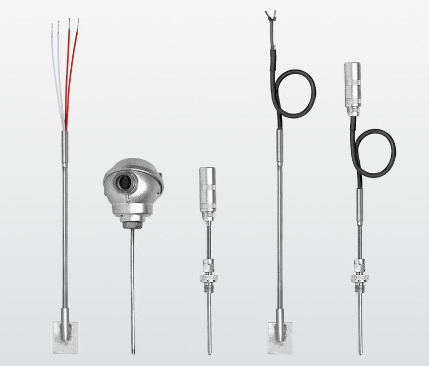
Measurement made easy
For plug-in connection
For screw-in connection
For surface measurement
—
Areas of application
• Universal application in general process engineering, tank
and piping construction, mechanical and plant
engineering
—
Electrical connections
• With compression fitting and fixed screw-in connection
• With weld-on plate for permanent surface measurement
• With molded part for tension clip mounting
—
Benefits
• Fastest possible measuring results through direct contact
of the mineral insulated cable with the medium
• Widest application ranges through optimum sheath
materials
• Subsequent installation possible by surface mounting
• Optimal usage due to a combination of mechanical and
electrical interfaces
• Global approvals for explosion protection up to Zone 0SENSYTEMP TSC400 INDUSTRIAL THERMOMETER | DS/TSC400-EN REV. C 3
—
Overview of temperature sensors
Type TSC420, with direct electrical connection
Dimensions in mm (in)
U = Installation length
N = Nominal length
ØA = Diameter of the mineral
insulated cable
Electrical connection Single and double thermocouples
Single Pt100 / 2-, 3-, or 4-wire
Double Pt100 / 2-, 3-, or 4-wire Double Pt100 / 2-wire Double Pt100 / 2- or 3-wire
Design Bendable mineral insulated cable with sealing sleeve
Open cable ends, standard 100 mm Form F connecting head Plug, socket
(3.94 in) or customer-specific
Type TSC430, with connection cable
Dimensions in mm (in)
U = Installation length
N = Nominal length
KL = Cable length
ØA = Diameter of the mineral
insulated cable
Electrical connection Single and double thermocouples
Single Pt100 / 2-, 3-, or 4-wire
Double Pt100 / 2-, 3-, or 4-wire Double Pt100 / 2- or 3-wire
Design Bendable mineral insulated cable with sealing sleeve and optional anti-kink spring 1
Open cable ends Plug, socket4 SENSYTEMP TSC400 INDUSTRIAL THERMOMETER | DS/TSC400-EN REV. C
—
… Overview of temperature sensors
Selectable process connections Insufficient nominal diameter
• Without process connection In the case of pipelines with very small nominal diameters,
• With fixed connection (please specify nominal length ‘N’ installation inside an elbow pipe is recommended. The
and installation length ‘U’) temperature sensor tip is set in opposition to the flow
• With movable connection (please specify nominal length direction of the measuring medium. Also installing the
‘N’ only) temperature sensor with an adapter at an acute angle
• With weld-on plate 25 x 25 x 3 mm (0.98 x 0.98 x 0.12 in) or against the flow direction can also distort measurement
35 x 25 x 3 mm (1.38 x 0.98 x 0.12 in) for surface results.
measurement
• With molded part for tension clip mounting
• Temperature sensor for use with or without thermowell
Installation instructions
The usual way of ensuring that thermal measurements are
accurate is to comply with the minimum installation length of
the temperature sensor. Ideally, in the case of pipelines, the
sensor on a thermometer should be located in the center of
the pipe. If this is not possible, both in the case of pipes and
containers, a minimum installation length of 10- to 15-times
the temperature sensor diameter is assumed to be sufficient.
Figure 2: Installation with small nominal diameter
Figure 1: Recommended installationSENSYTEMP TSC400 INDUSTRIAL THERMOMETER | DS/TSC400-EN REV. C 5
—
Specification
Resistance thermometer
The use of a mineral insulated cable and special sensors, Wire wound resistor (WW) – extended measuring range
including their installation, makes the vibration resistance of
all SensyTemp TSC400 industrial thermometers very high. Meas. range Vibration resistance
The peak-to-peak acceleration values of 30 m/sec2 (3 g) for
Class B −196 to 600 °C 100 m/sec2 (10 g) at 10
frequencies between 10 and 500 Hz (already defined in
(−320.8 to 1112 °F) to 500 Hz
accordance with standard IEC 60751 for increased
Class A, single WW −100 to 450 °C
requirements) are exceeded by all industrial thermometers.
(−148 to 842 °F)
The optimally suitable combination of measuring range,
Class A, double WW 0 to 250 °C (32 to 482 °F)
diameter, accuracy, and vibration resistance can be taken
from the following tables.
Single sensor Double sensor
Thin film resistor (TF) – Base design 2-W 3-W 4-W 2-W 3-W 4-W
3.0 mm, class B
3.0 mm, class A
Meas. range Vibration resistance
4.5 mm, class B
Class B −50 to 400 °C (−58 to 752 °F) 100 m/sec2 (10 g) at 10
4.5 mm, class A
Class A −30 to 300 °C (−22 to 572 °F) to 500 Hz
6.0 mm, class B
Class AA 0 to 100 °C (32 to 212 °F)
6.0 mm, class A
Single sensor Double sensor
Accuracy classes of measurement resistors in
2-W 3-W 4-W 2-W 3-W 4-W
accordance with IEC 60751
3.0 mm, class B
Both thin film resistors and wire wound resistors in
3.0 mm, class A accordance with IEC 60751 can be used across the entire
4.5 mm, class B range of application (also with increased accuracy class AA or
4.5 mm, class A class A). Subsequently, only the accuracy class of the
6.0 mm, class B temperature range used can remain valid.
6.0 mm, class A Example: A sensor of class AA is used at 290 °C (554 °F). After
6.0 mm, class AA this albeit brief application, class A applies for this sensor.
Thin film resistor (TF), built-in
Class B Δt = ± (0.30 + 0.0050[t]) −50 to 400 °C (−58 to 752 °F)
Class A Δt = ± (0.15 + 0.0020[t]) −30 to 300 °C (−22 to 572 °F)
Class AA Δt = ± (0.10 + 0.0017[t]) 0 to 100 °C (32 to 212 °F)
Wire wound resistor (WW), built-in
Class B Δt = ± (0.30 + 0.0050[t]) −196 to 600 °C (−320.8 to 1112 °F)
Class A Δt = ± (0.15 + 0.0020[t]) −100 to 450 °C (−148 to 842 °F)6 SENSYTEMP TSC400 INDUSTRIAL THERMOMETER | DS/TSC400-EN REV. C
—
… Specification
Length data for the temperature sensor tip
The following table shows the minimum immersion length,
the temperature-sensitive length and the non-flexible length
at the tip of the temperature sensor.
Design Basic design Extended measuring
range
minimum immersion length 70 mm (2.8 in) 70 mm (2.8 in)
Temperature-sensitive length 7 mm (0.3 in) 50 mm (1.9 in)
Non-flexible length 30 mm (1.2 in) 60 mm (2.4 in)
Figure 3: Graphical representation of accuracy classes
Measuring errors with two-wire circuits
The electric resistance of the copper inner conductor of the
mineral insulated cable affects the measured value for two-
wire circuits and must be taken into consideration.
Electric resistance depends on the diameter and length of the
industrial thermometer.
If the error cannot be compensated metrologically, the
following reference values shall apply:
Industrial thermometer diameter Electric resistance / measured error
3.0 mm (0.12 in) 0.281 Ω/m / 0.7 °C/m
6.0 mm (0.24 in) 0.1 Ω/m / 0.25 °C/m
It is for this reason that ABB supplies three-wire / four-wire
circuit temperature sensors as standard.SENSYTEMP TSC400 INDUSTRIAL THERMOMETER | DS/TSC400-EN REV. C 7
Thermocouples
The accuracy classes of the thermocouples are in accordance Accuracy classes in accordance with IEC 60584,
with the IEC 60584 international standard. ABB also supplies DIN 43710 and ANSI MC96.1
in accordance with ANSI MC96.1 upon request.
Since the values of both standards differ only very slightly at IEC 60584
low temperatures (up to approx. 300 °C), ABB recommends Type Class Temperature range Maximum measuring
using thermocouples conforming to international standard (CL) error
IEC 60584. The tolerance specifications are presented in the
K (NiCr-Ni) 2 −40 to 333 °C ± 2.5 °C (± 4.5 °F)
table ‘Accuracy classes in accordance with IEC 60584’
N (NiCrSi-NiSi) (−40 to 631.4 °F)
333 to 1200 °C ±0.0075 x [t]
Version
(631.4 to 2192 °F)
Vibration-resistant up to 600 m/sec2 (60 g)
1 −40 to 375 °C ± 1.5 °C (± 2.7 °F)
(−40 to 707 °F)
1xK 2xK 1xJ 2xJ 1xN 2xN 1xE 2xE
375 to 1000 °C ±0.004 x [t]
1.5 mm, class 2 (707 to 1832 °F)
3.0 mm, class 2 J (Fe-CuNi) 2 -40 to 333 °C ± 2.5 °C (± 4.5 °F)
3.0 mm, class 1 (−40 to 631.4 °F)
4.5 mm, class 2 333 to 750 °C ±0.0075 x [t]
4.5 mm, class 1 (631.4 to 1382 °F)
6.0 mm, class 2 1 −40 to 375 °C ± 1.5 °C (± 2.7 °F)
6.0 mm, class 1 (−40 to 707 °F)
375 to 750 °C ±0.004 x [t]
Note (707 to 1382 °F)
Industrial thermometers with a diameter of 8 mm (0.31 in) are E (NiCr-CuNi) 2 −40 to 333 °C ± 2.5 °C (± 4.5 °F)
made up of a mineral insulated cable with a diameter of (−40 to 631.4 °F)
6.0 mm (0.24 in) and a sleeve pressed onto the temperature 333 to 900 °C ±0.0075 x [t]
sensor tip. (631.4 to 1652 °F)
1 −40 to 375 °C ± 1.5 °C (± 2.7 °F)
(−40 to 707 °F)
375 to 800 °C ±0.004 x [t]
(707 to 1472 °F)8 SENSYTEMP TSC400 INDUSTRIAL THERMOMETER | DS/TSC400-EN REV. C
—
… Specification
Length data for the temperature sensor tip
ANSI MC 96.1
The following table shows the temperature-sensitive length,
Type Class (CL) Temperature range Maximum measuring
the minimum immersion length, and the non-flexible length
error
at the tip of the temperature sensor.
K (NiCr-Ni), Standard 0 to 293 °C ± 2.2 °C (± 3.96 °F)
N (NiCrSi-NiSi) (32 to 559.4 °F)
Basic design
293 to 1250 °C ±0.0075 x [t]
minimum immersion length 70 mm (2.8 in)
(559.4 to 2282 °F)
Temperature-sensitive length 7 mm (0.3 in)
Special 0 to 275 °C ± 1.1 °C (± 1.98 °F)
Non-flexible length 30 mm (1.2 in)
(32 to 527 °F)
275 to 1250 °C ±0.004 x [t]
(527 to 2282 °F)
J (Fe-CuNi) Standard 0 to 293 °C ± 2.2 °C (± 3.96 °F)
(32 to 559.4 °F)
293 to 750 °C ±0.0075 x [t]
(559.4 to 1382 °F)
Special 0 to 275 °C ± 1.1 °C (± 1.98 °F)
(32 to 527 °F)
275 to 750 °C ±0.004 x [t]
(527 to 1382 °F)
Figure 4: Graphical representation of accuracy classes using type K and N in
accordance with IEC 60584 as examples. See tables for other types.SENSYTEMP TSC400 INDUSTRIAL THERMOMETER | DS/TSC400-EN REV. C 9
Resistance thermometers and thermocouples
Insulation resistance of measuring inset Maximum permissible operating temperature
The insulation resistance is measured between the outer Depending on the sensor type and material selected, the
sheath and measuring loop. If there are two measuring loops, lower temperature value in each case applies.
the insulation resistance between both measuring loops is
also measured. Sensor types Maximum operating temperature
Thanks to a special process used during manufacturing, ABB Thin film resistor (TF) 400 °C (752 °F)
measuring insets can boast outstanding insulation values Wire wound resistor (WW) 600 °C (1112 °F)
even at high temperatures.
Type K and N thermocouples 1200 °C (2192 °F)
Type J thermocouples 750 °C (1382 °F)
Insulation resistance Riso
Type E thermocouples 900 °C (1652 °F)
≥ 500 MΩ with a ambient temperature range from
Materials
15 to 35 °C (59 to 95 °F)
Stainless steel 1.4404 (ASTM 316L) 800 °C (1472 °F)
Stainless steel 1.4571 (ASTM 316Ti) 800 °C (1472 °F)
Air humidity
NiCr alloy 2.4816 (Inconel 600) 1100 °C (2012 °F)
< 80 %
Permissible ambient temperature at the closure of the The maximum operating temperatures and pressures
mineral insulated cable specified are maximum values and do not take into
consideration process-related stress.
The effects of viscosity, flow rate, pressure, and temperature
Design Ambient temperature
in the process usually cause these values to drop.
Standard −40 to 120 °C (−40 to 248 °F)
Optional −56 to 200 °C (−68.8 to 392 °F) Transport temperature / Storage temperature
−20 to 70 °C (−4 to 158 °F)
In type TSC430, the temperature limits of the connection
cables used should also be considered. See Connection cable
for the resistance thermometer on page 14 and Connection
cables for thermocouples on page 16.
Response times in accordance with IEC 60751 and
IEC 60584
Ø Temperature sensor Water 0.4 m/s Air 3 m/s
t0,5 t0,9 t0,5 t0,9
Resistance thermometer
3.0 mm (0.12 in) 1.5 4.5 15.0 50.0
4.5 mm (0.18 in) 2.5 6.3 24.7 75.5
6.0 mm (0.24 in) 4.0 9.7 43.5 105.0
Thermocouples
1.5 mm (0.06 in) 0.7 1.8 12.4 38.6
3.0 mm (0.12 in) 0.8 2.1 14.5 44.5
4.5 mm (0.18 in) 1.8 5.4 24.8 67.6
6.0 mm (0.24 in) 3.0 7.5 38.6 98.510 SENSYTEMP TSC400 INDUSTRIAL THERMOMETER | DS/TSC400-EN REV. C
—
Process connections
Process connections – screwed connections
Fixed connection Sliding connection
Figure 1: Screw connections types (examples)
Design Material Thread Mineral insulated cable [Ø mm (in)] Length of engaged Compression fitting
thread (TL) [mm (in)]
Fixed connection Stainless steel M8 x 1 3.0 (0.12) 6.5 (0.26) –
G¼ A 3.0 / 4.5 / 6.0 12.0 (0.47) –
G½ A (0.12 / 0.18 / 0.24) 14.0 (0.55) –
¼ in NPT 5.08 (0.20) –
½ in NPT 8.12 (0.32) –
Sliding connection Stainless steel M8 x 1 3.0 (0.12) 6.5 (0.26) PTFE or VA
G¼ A 3.0 / 4.5 / 6.0 12.0 (0.47) PTFE or VA
G½ A (0.12 / 0.18 / 0.24) 14.0 (0.55) PTFE or VA
¼ in NPT 5.08 (0.20) PTFE or VA
½ in NPT 8.12 (0.32) PTFE or VA
Note
In the version with fixed connection, the link between the connection and the mineral insulated cable is established using hard-
soldering. The process connections for mineral insulated cables with a diameter of 6 mm (0.24 in) and 8 mm (0.31 in) are
identical.SENSYTEMP TSC400 INDUSTRIAL THERMOMETER | DS/TSC400-EN REV. C 11 Process connections for surface thermometers Molded part for clip mounting All dimensions in mm (in) Figure 5: Molded part for clamp collars up to 500 mm (19.68 in), other versions available on request 1 Industrial thermometer 2 Material: Stainless steel 1.4571 (ASTM 316Ti) Figure 6: Weld-on plate for resistance thermometer, all dimensions in mm (in)
12                           SENSYTEMP TSC400 INDUSTRIAL THERMOMETER | DS/TSC400-EN REV. C

—
… Process connections

1 Industrial thermometer                                               2 Material: NiCr alloy 2.4816 (Inconel 600)

Figure 7: Weld-on plate for thermocouples, all dimensions in mm (in)
SENSYTEMP TSC400 INDUSTRIAL THERMOMETER | DS/TSC400-EN REV. C                                                           13

—
Electrical connections

                                 Lemo plug size 1S                                         Lemo socket size 1S
Dimensions in mm (in)

Type                             FFA                                                       PCA
Chassis                          Nickel-plated brass, gold-plated brass contacts, PEEK isolator, maximum 6 contacts
IP rating                        IP 54
Maximum ambient temperature      200 °C (392 °F)

                                 Thermocouple – standard plug                              Thermocouple – standard socket
Dimensions in mm (in)

Type                             Standard
Material                         Plastic
Maximum ambient temperature      200 °C (392 °F)

                                  Form F connecting head
Dimensions in mm (in)                                                                  Functions of the connection head
                                                                                       •    Housing of a coupler connector
                                                                                       •    Protection of the terminal compartment against
                                                                                            environmental influence

                                                                                       Ambient temperature
                                                                                       The ambient temperature on the Form F connection head
                                                                                       can be between -40 and 120 °C (-40 to 248 °F).
                                                                                       The most commonly used cable gland is suited for a
                                                                                       temperature range of −20 to 100 °C (−4 to 212 °F). For
                                                                                       temperatures outside this range, an appropriate cable
Chassis                           Aluminum epoxide coating, loose cover,
                                                                                       gland can be installed.
IP rating                         IP 65
Maximum ambient temperature       120 °C (248 °F)
14 SENSYTEMP TSC400 INDUSTRIAL THERMOMETER | DS/TSC400-EN REV. C
—
… Electrical connections
Connection cable for the resistance thermometer
Note
The specified outside diameters of the connection cable are batch-dependent and should be treated as guideline values.
The color coding of the wires for the resistance thermometer is in accordance with IEC 60751.
See also ‘Electrical connections’ in the operating instruction OI/TSC400.
PFA cable TFT – coding T2 PFA cable TFTV – coding T3
1 PFA wire insulation (T) 3 PFA sheath (T)
2 Aluminum foil with silver-plated copper strand (F) 4 Mesh made of stainless steel (V)
Figure 8: PFA cable
Design Design Sensor design
PFA cable TFT – General: 1 x Pt100 / 2-w. – coding P1
coding T2 Stranded wire, wire material: solid copper 1 x Pt100 / 3-w. – coding P2
Temperature resistance of the insulation: −200 to 200 °C (−328 to 392 °F) 1 x Pt100 / 4-w. – coding P3
Up to 4 wires: 2 x Pt100 / 2-w. – coding P4
Outside diameter: approx. 4.8 mm (0.19 in), conductor cross-section: 0.75 mm2 2 x Pt100 / 3-w. – coding P5
From 6 wires: 2 x Pt100 / 4-w. – coding P6
Outside diameter: approx. 4.5 mm (0.18 in), conductor cross-section: 0.22 mm2
PFA cable TFTV – General:
coding T3 Stranded wire, wire material: solid copper
Temperature resistance of the insulation: −200 to 200 °C (−328 to 392 °F)
Up to 4 wires:
Outside diameter: approx. 4.0 mm (0.16 in), conductor cross-section: 0.22 mm2
From 6 wires:
Outside diameter: approx. 5.5 mm (0.22 in), conductor cross-section: 0.22 mm2SENSYTEMP TSC400 INDUSTRIAL THERMOMETER | DS/TSC400-EN REV. C 15
PVC cable JJ – coding P2 PVC cable JFJ – coding P3
1 PVC wire insulation (J) 3 PVC sheath (J)
2 Film with wire mesh (F)
Figure 9: PVC cable
Design Design Sensor design
PVC cable JJ – coding P2 Outside diameter approx. 5.5 mm (0.22 in) 1 x Pt100 / 2-w. – coding P1
Conductor cross-section: 0.22 mm2, Wire material: copper strand 1 x Pt100 / 3-w. – coding P2
Temperature resistance of the insulation: −20 to 105 °C (−4 to 221 °F) 1 x Pt100 / 4-w. – coding P3
PVC cable JFJ – coding P3 Outside diameter approx. 5.5 mm (0.22 in) 2 x Pt100 / 2-w. – coding P4
Conductor cross-section: 0.50 mm2, Wire material: copper strand
Temperature resistance of the insulation: −10 to 105 °C (14 to 221 °F)16 SENSYTEMP TSC400 INDUSTRIAL THERMOMETER | DS/TSC400-EN REV. C
—
… Electrical connections
Connection cables for thermocouples
Note
The specified outside diameters of the connection cable are batch-dependent and should be treated as guideline values.
Type Class of upper/lower deviation Application temperature range
Class 1 Class 2
JX ± 85 μV (± 1.5 °C (34.7 °F)) – –25 to 200 °C (-13 to 392 °F)
EX ± 120 μV (± 1.5 °C (34.7 °F)) – –25 to 200 °C (-13 to 392 °F)
NX ± 60 μV (± 1.5 °C (34.7 °F)) – –25 to 200 °C (-13 to 392 °F)
KCA – ± 100 μV (± 2.5 °C (36.5 °F)) 0 °C to 150 °C (32 to 302 °F):
PVC cable JFJ – coding P3 Silicone cable SLSLGL – coding S3
1 PVC wire insulation, overmolded (J) 4 Silicone rubber wire insulation, overmolded (SL)
2 Plastic-laminated aluminum foil shield (F) 5 Silicone rubber sheath (SL)
3 PVC sheath (J) 6 Glass filament mesh (GL)
Figure 10: PVC and silicone cable
Design Design Sensor design
PVC cable JFJ – coding P3 General: 1 x JX – coding J1
Stranded wire, conductor cross-section: 0.22 mm2, Temperature resistance of the insulation: 2 x JX – coding J2
−10 to 105 °C (14 to 221 °F)
Type JX: 1 x KCA – coding K1
Outside diameter up to 4 wires approx. 5.8 mm (0.23 in) 2 x KCA – coding K2
Type KCA:
Outside diameter up to 4 wires approx. 5.0 mm (0.20 in)
Silicone cable SLSLGL – Stranded wire, conductor cross-section: 0.22 mm2, Temperature resistance of the insulation: 1 x KCA – coding K1
coding S3 −200 to 200 °C (−328 to 392 °F) 2 x KCA – coding K2
Outside diameter up to 2 wires approx. 4.7 mm (0.19 in)
Outside diameter up to 4 wires approx. 5.5 mm (0.22 in)SENSYTEMP TSC400 INDUSTRIAL THERMOMETER | DS/TSC400-EN REV. C 17
PFA cable TCUT – coding T2 PFA cable TGLV – coding T4
1 PFA wire insulation, overmolded (T) 4 Glass filament mesh (GL)
2 Tinned mesh (CU) 5 Mesh made of stainless steel (V)
3 PFA sheath, overmolded (T)
Figure 11: PFA cable
Design Design Sensor design
PFA cable TCUT – coding T2 Stranded wire, conductor cross-section: 0.22 mm2 1 x NX – coding N1
Temperature resistance of the insulation: −200 to 200 °C (−328 to 392 °F)
Outside diameter approx. 3.0 mm (0.12 in)
PFA cable TGLV – coding T4 General: 1 x JX – coding J1
With single thermocouple: parallel wire 2 x JX – coding J2
With double thermocouple: stranded wire
Conductor cross-section: 0.22 mm2 1 x KCA – coding K1
Temperature resistance of the insulation: −200 to 200 °C (−328 to 392 °F) 2 x KCA – coding K2
Type JX:
Outside diameter with 2 wires (oval conductor): approx. 3.3 mm x 2.0 mm (0.13 x 0.08 in) 1 x NX – coding N1
Outside diameter up to 4 wires approx. 3.7 mm (0.15 in) 2 x NX – coding N2
Type KCA:
Outside diameter with 2 wires (oval conductor): approx. 3.3 mm x 2.0 mm (0.13 x 0.08 in) 1 x EX – coding E1
Outside diameter up to 4 wires approx. 3.7 mm (0.15 in) 2 x EX – coding E2
Type NX:
Outside diameter up to 4 wires approx. 3.5 mm (0.14 in)
Type EX:
Outside diameter up to 4 wires approx. 3.4 mm (0.13 in)18 SENSYTEMP TSC400 INDUSTRIAL THERMOMETER | DS/TSC400-EN REV. C
—
Use in potentially explosive atmospheres
Intrinsic safety type of protection approvals (Ex i)
The SensyTemp TSC400 temperature sensors are equipped Output power P o with ABB transmitters
with the following approvals.
ATEX approvals are valid throughout the EU and in Transmitter type Po
Switzerland, IECEx approvals are recognized internationally. TTxx00 ≤ 38 mW
The device has the following approvals (examination
The type examination certificates for the corresponding
certificates):
transmitters contain all further information necessary to
• ATEX Ex i, PTB 01 ATEX 2200 X
verify intrinsic safety (Uo, Io, Poo, Lo, Co etc.).
• IECEx Ex i, IECEx PTB 11.0111 X
Note
A list of applied standards including the output data with
Temperature sensors for use in Zone 0 may only contain an
which the device is in conformity can be found in the (EC
intrinsically safe circuit and may only be connected to
type) examination certificate.
declared intrinsically safe circuits with type of protection ‘Ex
ia’.
Additional approvals available for the TSC400 temperature
sensor are available on request.
Temperature data
Industrial thermometers that conform to the requirements of
both the type examination certificate for ATEX ‘Ex i’ and Thermal resistance
NAMUR-specification NE24, are available on request. The thermal resistances for mineral insulated cables are
listed in the following table.
The values are specified under ‘gas with a flow velocity of 0
Electrical data m/s’ conditions.
All of the values listed below are valid assuming that an
additional transmitter has been connected. Thermal resistance Rth Diameter of the mineral insulated
The following electric values must not be up-scaled: Δt = 200 K/W x 0.038 W = 7.6 K cable
< 6 mm (0.24 in) ≥ 6 mm (0.24 in)
Ui (input voltage) Ii (input current) Resistance thermometer 200 K/W 84 K/W
30 V 101 mA Thermocouple 30 K/W 30 K/W
25 V 158 mA K/W = kelvin per watt
20 V 309 mA
Pi (internal power) = max. 0.5 W
Li (internal inductance) = 15 μH/m
Ci (internal capacitance) = 280 pF/m
Note
For the internal power Pi of the sensor and the output power Po of the
connected transmitter, the following must apply: Pi ≥ Po.
Likewise the following must apply: Ui ≥ Uo and Ii ≥ Io.
The output values of a connected transmitter, both when
mounting in the connection head and when mounting in the
field, must not up-scale these electric values. The output
values of ABB temperature transmitters (TTx300 and TTx200)
are below these maximum values.SENSYTEMP TSC400 INDUSTRIAL THERMOMETER | DS/TSC400-EN REV. C 19
Temperature rise in the event of a fault Maximum process temperature T medium in Zone 0 and
In the event of a fault, the temperature sensors will exhibit a Zone 1
temperature rise Δt as appropriate for the applied power. To calculate the temperature classes for T3, T4, T5 and T6,
This temperature rise Δt must be taken into account when deduct 5 K in each instance from the maximum surface
determining the maximum process temperature for each temperature; for T1 and T2, deduct 10 K in each instance from
temperature class. this surface temperature.
For temperature Tmedium, the temperature rise in the event of
Note a fault of 8 K as calculated as an example in Temperature rise
In the event of a fault (short-circuit), the dynamic short- in the event of a fault on page 19.
circuit current that occurs in the measurement circuit for a
matter of milliseconds is not relevant with regard to Temperature class −5 K -10 K Tmedium
temperature rise. T1 (450 °C (842 °F)) — 440 °C (824 °F)432 °C (809.6 °F)
T2 (300 °C (572 °F)) — 290 °C (554 °F) 282 °C (539.6 °F)
The temperature rise Δt can be calculated using the following T3 (200 °C (392 °F)) 195 °C (383 °F) — 187 °C (368.6 °F)
formula: T4 (135 °C (275 °F)) 130 °C (266 °F) — 122 °C (251.6 °F)
t Rth Po K / W W
T5 (100 °C (212 °F)) 95 °C (203 °F) — 87 °C (188.6 °F)
T6 (85 °C (185 °F)) 80 °C (176 °F) — 72 °C (161.6 °F)
∆t Temperature rise
Rth Thermal resistance
Po Output power of an additional connected transmitter
Example:
Resistance thermometer diameter 3 mm (0.12 in):
Rth = 200 K/W
Temperature transmitter TTxx00 Po= 38 mW, see also Output
power Po with ABB transmitters on page 18.
Δt = 200 K/W x 0.038 W = 7.6 K
Therefore, at transmitter output power Po = 38 mW, the
temperature rise in the event of a fault is approximately 8 K.
This results in the following maximum possible process
temperatures Tmedium, as shown in Table Maximum process
temperature Tmedium in Zone 0 and Zone 1 on page 19.
Note
For a higher output power Po as 38 mW in case of failure, but
also for a generally higher output power of a
connected transmitter as 38 mW, the
temperature increase Δt must be recalculated.20 SENSYTEMP TSC400 INDUSTRIAL THERMOMETER | DS/TSC400-EN REV. C
—
Tests and certificates
In order to increase the safety and accuracy of the process,
ABB offers various mechanical and electrical tests. The
results are confirmed with certificates in accordance with
EN 10204.
Certificates
• Declaration of compliance 2.1 for order conformity
• Inspection certificate 3.1 for the following tests:
– Material certificate for the MI-Cable
– Visual, dimensional and function checks of the
temperature sensor
– Reference measurement for temperature sensor
For measurements requiring extremely high accuracy, ABB
offers a calibration of the temperature sensor in its own
DAkkS-calibration laboratory.
With a DAkkS-calibration, a separate calibration certificate is
provided for each temperature sensor.
To obtain meaningful measurement results, the following
minimum lengths of the mineral insulated cable should be
adhered to:
Temperature range Recommended minimum lengths
For very low temperatures below 300 mm
−70 °C (−94 °F) (11.81 in)
For low to medium temperatures 100 to 150 mm
(3.94 to 5.91 in)
For temperatures above 500 °C 300 to 400 mm (11.81 to 15.75 in)
(932 °F)
Greater lengths allow additional measurement methods and
simplify the measuring process. If you require any further
information, please contact your local ABB partner.
In case of a reference measurements and DAkkS-calibration,
the individual sensor characteristic of the temperature
sensor can also be calculated and a suitable transmitter can
be accordingly programmed using a freestyle characteristic.
The measuring accuracy of the temperature sensor can be
considerably improved by adjusting the transmitter to the
sensor characteristics. To this end, the measurement must
be conducted with at least three temperatures.SENSYTEMP TSC400 INDUSTRIAL THERMOMETER | DS/TSC400-EN REV. C 21 — Ordering Information NOTE Order codes cannot be combined at will. Your ABB partner will be happy to answer any questions you might have regarding installation feasibility. All documentation, declarations of conformity, and certificates are available in ABB's download area. SensyTemp TSC420 Base model TSC420 XX XX XX XX XX XX XX XX XX TSC420 Screw-in thermometer with direct electrical connection Explosion Protection Certification Without explosion protection Y0 Intrinsic Safety ATEX II 1 G Ex ia IIC T6...T1 Ga, Zone 0 A1 Intrinsic Safety ATEX II 2 G Ex ib IIC T6...T1 Gb, Zone 1 A2 Intrinsic Safety IECEx ia IIC T6...T1 Ga, Zone 0 H1 NEPSI Intrinsic Safety type of protection: Ex ia IIC T6 Ga S1 Mounting Type Wihout fitting F0 Fixed connection F1 Compression fitting, clamp ring material PTFE F2 Compression fitting, clamp ring material stainless steel F3 Weld-on pad 25 mm x 25 mm x 3 mm (for Thermocouple) W2 Weld-on pad 35 mm x 25 mm x 3 mm (for Pt100) W3 Clamping adapter (please define clip separately) C1 Others Z9 Sensor Type and Wiring 1 x Pt100, two-wire circuit P1 1 x Pt100, three-wire circuit P2 1 x Pt100, four-wire circuit P3 2 x Pt100, two-wire circuit P4 2 x Pt100, three-wire circuit P5 2 x Pt100, four-wire circuit P6 1 x Type K (NiCr-NiAl) K1 2 x Type K (NiCr-NiAl) K2 1 x Type J (Fe-CuNi) J1 2 x Type J (Fe-CuNi) J2 1 x Type N (NiCrSi-NiSi) N1 2 x Type N (NiCrSi-NiSi) N2 1 x Type E (NiCr-CuNi) E1 2 x Type E (NiCr-CuNi) E2 Others Z9
22                           SENSYTEMP TSC400 INDUSTRIAL THERMOMETER | DS/TSC400-EN REV. C

—
… Ordering Information

SensyTemp TSC420                                                                             XX   XX   XX   XX   XX   XX
Sensor / Accuracy Class
Wire Wound, Accuracy Class B, IEC 60751, Range −196 to 600 °C (−321 to 1112 °F)              B2
Wire Wound, Double, Accuracy Class A, IEC 60751, Range 0 to 250 °C (32 to 482 °F)            D2
Wire Wound, Accuracy Class A, IEC 60751, Range −100 to 450 °C (−148 to 842 °F)               D1
Thin Film, Accuracy Class B, IEC 60751, Range −50 to 400 °C (−58 to 752 °F)                  S5
Thin Film, Accuracy Class A, IEC 60751, Range −30 to 300 °C (−22 to 572 °F)                  S1
Thin Film, Accuracy Class AA, IEC 60751, Range 0 to 100 °C (32 to 212 °F)                    S3
Thermocouple, Accuracy Class 2, IEC 60584                                                    T2
Thermocouple, Accuracy Class 1, IEC 60584                                                    T1
Others                                                                                       Z9
Mineral Insulated Cable Diameter
1,5 mm                                                                                            C2
3,0 mm                                                                                            D3
4,5 mm                                                                                            C5
6,0 mm                                                                                            D6
6,0 mm, tip with sleeve 8.0 mm                                                                    H8
Others                                                                                            Z9
Mineral Insulated Cable Material
Stainless steel 316Ti (1.4571)                                                                         S1
Stainless steel 316L (1.4404)                                                                          S2
Inconel Alloy 600 (2.4816)                                                                             J1
Others                                                                                                 Z9
Process Connection Type
Without                                                                                                     Y0
Parallel thread M8 x 1                                                                                      M1
Parallel thread G ¼ A                                                                                       G1
Parallel thread G ½ A                                                                                       G2
Tapered thread ¼ in. NPT                                                                                    N1
Tapered thread ½ in. NPT                                                                                    N2
Others                                                                                                      Z9
SENSYTEMP TSC400 INDUSTRIAL THERMOMETER | DS/TSC400-EN REV. C                     23

SensyTemp TSC420                                                                                       XX   XX
Electrical Connetion
Head type F / aluminium                                                                                C7
Open wires, length 100 mm (4 in.), standard length                                                     C1
Open wires, customer specific length                                                                   C8
Thermocouple-plug, size: standard                                                                      C3
Thermocouple-socket, size: standard                                                                    C4
Lemo-plug, size: 1S                                                                                    C5
Lemo-socket, size: 1S                                                                                  C6
Others                                                                                                 Z9
Length Unit of Measure
Millimeter (mm)                                                                                             U1
Inches (in.)                                                                                                U3

SensyTemp TSC420                                                                                  XX   XX   XX
Certificates
Inspection certificate according EN 10204-3.1, material monitoring for wetted parts               C2
Declaration of compliance according EN 10204-2.1, with the order                                  C4
Inspection certificate according EN 10204-3.1, visual, dimensional and functional test            C6
Inspection certificate according EN 10204-3.1, sensor calibration, single RTD                     CD
Inspection certificate according EN 10204-3.1, sensor calibration, double RTD                     CE
Inspection certificate according EN 10204-3.1, sensor calibration, single thermocouple            CF
Inspection certificate according EN 10204-3.1, sensor calibration, double thermocouple            CG
DAkkS sensor calibration, single RTD, separate calibration certificate per thermometer            CH
DAkkS sensor calibration, double RTD, separate calibration certificate per thermometer            CJ
DAkkS sensor calibration, single thermocouple, separate calibration certificate per thermometer   CK
DAkkS sensor calibration, double thermocouple, separate calibration certificate per thermometer   CL
Number of Calibration Test Points
1 point                                                                                                P1
2 points                                                                                               P2
3 points                                                                                               P3
4 points                                                                                               P4
5 points                                                                                               P5
24                         SENSYTEMP TSC400 INDUSTRIAL THERMOMETER | DS/TSC400-EN REV. C

—
… Ordering Information

SensyTemp TSC420                                                                                    XX   XX   XX   XX   XX
Temperatures for Sensor Calibration
Standard calibration: 0 °C (32 °F)                                                                  V1
Standard calibration: 100 °C (212 °F)                                                               V2
Standard calibration: 400 °C (752 °F)                                                               V3
Standard calibration: 0 °C and 100 °C (32 °F and 212 °F)                                            V4
Standard calibration: 0 °C and 400 °C (32 °F and 752 °F)                                            V5
Standard calibration: 0 °C, 100 °C and 200 °C (32 °F, 212 °F and 392 °F)                            V7
Standard calibration: 0 °C, 200 °C and 400 °C (32 °F, 392 °F and 752 °F)                            V8
Standard calibration: Customer specific temperatures                                                V6
DAkkS calibration: 0 °C (32 °F)                                                                     D1
DAkkS calibration: 100 °C (212 °F)                                                                  D2
DAkkS calibration: 400 °C (752 °F)                                                                  D3
DAkkS calibration: 0 °C and 100 °C (32 °F and 212 °F)                                               D4
DAkkS calibration: 0 °C and 400 °C (32 °F and 752 °F)                                               D5
DAkkS calibration: 0 °C, 100 °C and 200 °C (32 °F, 212 °F and 392 °F)                               D7
DAkkS calibration: 0 °C, 200 °C and 400 °C (32 °F, 392 °F and 752 °F)                               D8
DAkkS calibration: Customer specific temperatures                                                   D6
Pipe Clamp
Clamping diameter 20 mm up to 40 mm                                                                      S1
Clamping diameter 40 mm up to 60 mm                                                                      S2
Clamping diameter 60 mm up to 80 mm                                                                      S3
Clamping diameter 80 mm up to 100 mm                                                                     S4
Clamping diameter 100 mm up to 120 mm                                                                    S5
Clamping diameter 120 mm up to 140 mm                                                                    S6
Clamping diameter 140 mm up to 160 mm                                                                    S7
Clamping diameter 160 mm up to 180 mm                                                                    S8
Clamping diameter 180 mm up to 200 mm                                                                    S9
Clamping diameter more than 200 mm                                                                       SZ
Other Options
Hot junction grounded                                                                                         J1
Mineral insulated cable sealed, up to 200 °C (392 °F)                                                         J6
Documentation Language
German                                                                                                             M1
English                                                                                                            M5
Language package Western Europe / Scandinavia (Languages: DE, EN, DA, ES, FR, IT, NL, PT, FI, SV)                  MW
Language package Eastern Europe (Languages: DE, EL, CS, ET, LV, LT, HU, PL, SK, SL, RO, BG)                        ME
Additional TAG Plate
Stainless steel plate with TAG no., lasered                                                                             T1
SENSYTEMP TSC400 INDUSTRIAL THERMOMETER | DS/TSC400-EN REV. C                                       25

SensyTemp TSC430

Base model                                                             TSC430 XX     XX     XX   XX   XX   XX   XX   XX   XX   XX
TSC430 Sheated cable thermometer with connection cable
Explosion Protection Certification
Without explosion protection                                                   Y0
Intrinsic Safety ATEX II 1 G Ex ia IIC T6...T1 Ga, Zone 0                      A1
Intrinsic Safety ATEX II 2 G Ex ib IIC T6...T1 Gb, Zone 1                      A2
Intrinsic Safety IECEx ia IIC T6...T1 Ga, Zone 0                               H1
NEPSI Intrinsic Safety type of protection: Ex ia IIC T6 Ga                     S1
Mounting Type
Wihout fitting                                                                       F0
Fixed connection                                                                     F1
Compression fitting, clamp ring material PTFE                                        F2
Compression fitting, clamp ring material stainless steel                             F3
Weld-on pad 25 mm x 25 mm x 3 mm (for Thermocouple)                                  W2
Weld-on pad 35 mm x 25 mm x 3 mm (for Pt100)                                         W3
Clamping adapter (please define clip separately)                                     C1
Others                                                                               Z9
Sensor Type and Wiring
1 x Pt100, 2-wire                                                                           P1
1 x Pt100, 3-wire                                                                           P2
1 x Pt100, 4-wire                                                                           P3
2 x Pt100, 2-wire                                                                           P4
2 x Pt100, 3-wire                                                                           P5
2 x Pt100, 4-wire                                                                           P6
1 x Type K (NiCr-NiAl)                                                                      K1
2 x Type K (NiCr-NiAl)                                                                      K2
1 x Type J (Fe-CuNi)                                                                        J1
2 x Type J (Fe-CuNi)                                                                        J2
1 x Type N (NiCrSi-NiSi)                                                                    N1
2 x Type N (NiCrSi-NiSi)                                                                    N2
1 x Type E (NiCr-CuNi)                                                                      E1
2 x Type E (NiCr-CuNi)                                                                      E2
Others                                                                                      Z9
26                           SENSYTEMP TSC400 INDUSTRIAL THERMOMETER | DS/TSC400-EN REV. C

—
… Ordering Information
Main ordering information SensyTemp TSC430                                                   XX   XX   XX   XX   XX
Sensor / Accuracy Class
Wire Wound, Accuracy Class B, IEC 60751, Range -196 to 600 °C (-321 to 1112 °F)              B2
Wire Wound, Double, Accuracy Class A, IEC 60751, Range 0 to 250 °C (32 to 482 °F)            D2
Wire Wound, Accuracy Class A, IEC 60751, Range -100 to 450 °C (-148 to 842 °F)               D1
Thin Film, Accuracy Class B, IEC 60751, Range -50 to 400 °C (-58 to 752 °F)                  S5
Thin Film, Accuracy Class A, IEC 60751, Range -30 to 300 °C (-22 to 572 °F)                  S1
Thin Film, Accuracy Class AA, IEC 60751, Range 0 to 100 °C (32 to 212 °F)                    S3
Thermocouple, Accuracy Class 2, IEC 60584                                                    T2
Thermocouple, Accuracy Class 1, IEC 60584                                                    T1
Others                                                                                       Z9
Mineral Insulated Cable Diameter
1,5 mm                                                                                            C2
3,0 mm                                                                                            D3
4,5 mm                                                                                            C5
6,0 mm                                                                                            D6
6,0 mm, tip with sleeve 8.0 mm                                                                    H8
Others                                                                                            Z9
Mineral Insulated Cable Material
Stainless steel 316Ti (1.4571)                                                                         S1
Stainless steel 316L (1.4404)                                                                          S2
Inconel Alloy 600 (2.4816)                                                                             J1
Others                                                                                                 Z9
Process Connection Type
Without                                                                                                     Y0
Parallel thread M8 x 1                                                                                      M1
Parallel thread G 1/4 A                                                                                     G1
Parallel thread G 1/2 A                                                                                     G2
Tapered thread 1/4 in. NPT                                                                                  N1
Tapered thread 1/2 in. NPT                                                                                  N2
Others                                                                                                      Z9
Electrical Connetion
Open wires                                                                                                       C2
Thermocouple-plug, size: standard                                                                                C3
Thermocouple-socket, size: standard                                                                              C4
Lemo-plug, size: 1S                                                                                              C5
Lemo-socket, size: 1S                                                                                            C6
Others                                                                                                           Z9
SENSYTEMP TSC400 INDUSTRIAL THERMOMETER | DS/TSC400-EN REV. C         27

Main ordering information SensyTemp TSC430                                                  XX   XX
Connection Cable Type
JJ (PVC / PVC), up to 105 °C (221 °F)                                                       P2
JFJ(PVC/Alu Foil with additional tinned wire 0,50 mm/PVC), up to 105 °C (221 °F)            P3
SLSLGL (silicone / silicone / glas fibre) up to 200°C (392 °F)                              S3
TFT (PFA / Alu Foil / PFA), up to 200 °C (392 °F)                                           T2
TFTV (PFA / Alu Foil / PFA / SST wire braid), up to 200 °C (392 °F)                         T3
TGLV (PFA / Glas fibre / SST wire braid), up to 200 °C (392 °F)                             T4
Others                                                                                      Z9
Length Unit of Measure
Millimeter (mm)                                                                                  U1
Inches (in.)                                                                                     U3

Additional ordering information

SensyTemp TSC430                                                                            XX   XX
Certificates
Inspection certificate according EN 10204-3.1, material monitoring for wetted parts         C2
Declaration of compliance according EN 10204-2.1, with the order                            C4
Inspection certificate according EN 10204-3.1, visual, dimensional and functional test      C6
Inspection certificate according EN 10204-3.1, sensor calibration, single RTD               CD
Inspection certificate according EN 10204-3.1, sensor calibration, double RTD               CE
Inspection certificate according EN 10204-3.1, sensor calibration, single thermocouple      CF
Inspection certificate according EN 10204-3.1, sensor calibration, double thermocouple      CG
DAkkS sensor calibration, single RTD, calibration certificate per thermometer               CH
DAkkS sensor calibration, double RTD, calibration certificate per thermometer               CJ
DAkkS sensor calibration, single thermocouple, calibration certificate per thermometer      CK
DAkkS sensor calibration, double thermocouple, calibration certificate per thermometer      CL
Number of Calibration Test Points
1 point                                                                                          P1
2 points                                                                                         P2
3 points                                                                                         P3
4 points                                                                                         P4
5 points                                                                                         P5
28                         SENSYTEMP TSC400 INDUSTRIAL THERMOMETER | DS/TSC400-EN REV. C

—
… Ordering Information

SensyTemp TSC430                                                                                    XX   XX   XX   XX   XX
Temperatures for Sensor Calibration
Standard calibration: 0 °C (32 °F)                                                                  V1
Standard calibration: 100 °C (212 °F)                                                               V2
Standard calibration: 400 °C (752 °F)                                                               V3
Standard calibration: 0 °C and 100 °C (32 °F and 212 °F)                                            V4
Standard calibration: 0 °C and 400 °C (32 °F and 752 °F)                                            V5
Standard calibration: 0 °C, 100 °C and 200 °C (32 °F, 212 °F and 392 °F)                            V7
Standard calibration: 0 °C, 200 °C and 400 °C (32 °F, 392 °F and 752 °F)                            V8
Standard calibration: Customer specific temperatures                                                V6
DAkkS calibration: 0 °C (32 °F)                                                                     D1
DAkkS calibration: 100 °C (212 °F)                                                                  D2
DAkkS calibration: 400 °C (752 °F)                                                                  D3
DAkkS calibration: 0 °C and 100 °C (32 °F and 212 °F)                                               D4
DAkkS calibration: 0 °C and 400 °C (32 °F and 752 °F)                                               D5
DAkkS calibration: 0 °C, 100 °C and 200 °C (32 °F, 212 °F and 392 °F)                               D7
DAkkS calibration: 0 °C, 200 °C and 400 °C (32 °F, 392 °F and 752 °F)                               D8
DAkkS calibration: customer specific temperatures                                                   D6
Pipe Clamp
without                                                                                                  S0
Clamping diameter 20 mm up to 40 mm                                                                      S1
Clamping diameter 40 mm up to 60 mm                                                                      S2
Clamping diameter 60 mm up to 80 mm                                                                      S3
Clamping diameter 80 mm up to 100 mm                                                                     S4
Clamping diameter 100 mm up to 120 mm                                                                    S5
Clamping diameter 120 mm up to 140 mm                                                                    S6
Clamping diameter 140 mm up to 160 mm                                                                    S7
Clamping diameter 160 mm up to 180 mm                                                                    S8
Clamping diameter 180 mm up to 200 mm                                                                    S9
Clamping diameter more than 200 mm                                                                       SZ
Other Options
Hot junction grounded                                                                                         J1
Mineral insulated cable, sealed, up to 200 °C (392 °F)                                                        J6
Anti-kink spring for connecting cable                                                                         J8
Documentation Language
German                                                                                                             M1
English                                                                                                            M5
Language package Western Europe / Scandinavia (Languages: DE, EN, DA, ES, FR, IT, NL, PT, FI, SV)                  MW
Language package Eastern Europe (Languages: DE, EL, CS, ET, LV, LT, HU, PL, SK, SL, RO, BG)                        ME
Additional TAG Plate
Stainless steel plate with TAG no.                                                                                      T1
SENSYTEMP TSC400 INDUSTRIAL THERMOMETER | DS/TSC400-EN REV. C                29

Accessories

Accessories                                                                                  Order code
TSC400 Commissioning Instruction, German                                                3KXT121400R4403
TSC400 Commissioning Instruction, English                                               3KXT121400R4401
TSC400 Commissioning Instruction, Language package Western Europe / Scandinavia         3KXT121400R4493
TSC400 Commissioning Instruction, Language package Eastern Europe                       3KXT121400R4494
30                        SENSYTEMP TSC400 INDUSTRIAL THERMOMETER | DS/TSC400-EN REV. C

—
Trademarks
Inconel is a registered trademark of Special Metals Corporation

‘Electrical connections’ in the operating instruction

 Sales              Service
SENSYTEMP TSC400 INDUSTRIAL THERMOMETER | DS/TSC400-EN REV. C 31
—
ABB Measurement & Analytics

For your local ABB contact, visit:
www.abb.com/contacts

For more product information, visit:
www.abb.com/temperature
                                                                                                           01.2021

—
We reserve the right to make technical changes or modify the contents of this document without
prior notice. With regard to purchase orders, the agreed particulars shall prevail.
                                                                                                           DS/TSC400-EN Rev. C

ABB does not accept any responsibility whatsoever for potential errors or possible lack of information
in this document.
We reserve all rights in this document and in the subject matter and illustrations contained therein.
Any reproduction, disclosure to third parties or utilization of its contents – in whole or in parts – is
forbidden without prior written consent of ABB.
Copyright© 2021 ABB
All rights reserved                                   3KXT121400R1001
You can also read