FDOTConnect OpenRoads Designer Pond Design & Plans Development - for - Training Guide
←
→
Page content transcription
If your browser does not render page correctly, please read the page content below
State of Florida
     Department of Transportation

    FDOTConnect
                    for
OpenRoads Designer

   Pond Design &
Plans Development

           Training Guide
                     2021
     PRODUCTION SUPPORT CADD OFFICE
          TALLAHASSEE, FLORIDA
           https://www.fdot.gov/cadd/

  Pond Design & Plans Development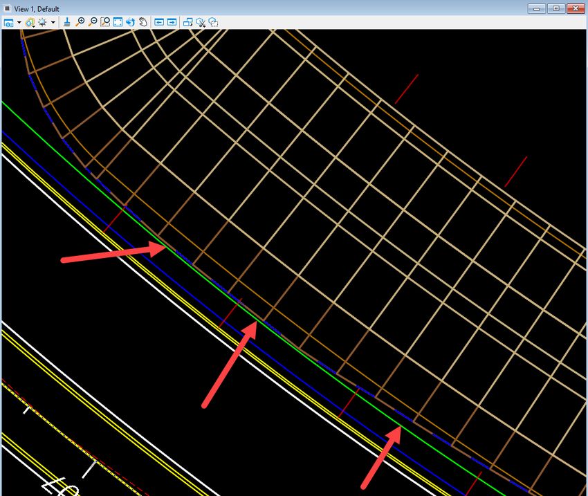
Description
    This course was developed to introduce the OpenRoads Designer CONNECT Edition tools for Pond Design and
    modeling on Florida Department of Transportation (FDOT) projects. The curriculum was developed within the
    FDOTCONNECT Workspace to provide sample exercises for many of the Pond Design Tools on a sample project
    data set. Participants of this course will be introduced to the newest OpenRoads environment and a Workflow
    for designing two dimensional (2D) plans, profiles, and three dimensional (3D) models for Pond Design
    Construction Deliverables.
Objectives
              •   Finding additional learning resources and training materials for OpenRoads Designer CONNECT
                  Edition and the general process using Drainage and Utilities Workflow for Pond Design
              •   How to create and prepare a Pond Design file for use in construction Deliverables
              •   Laying out a simple Pond
              •   Tools to evaluate and edit the Pond Design
              •   Producing a NexGen Storm Water Facilities sheet (according to FDM 917)
Audience
                  FDOT Drainage Designers and Engineers.
Prerequisites
Participants need to have a basic understanding of Computer Aided Drafting and Design (CADD) using MicroStation,
     a basic understanding of OpenRoads Designer CONNECT Edition - OpenRoads Technology tools and a solid
     understanding of the engineering necessary to design Ponds on a Roadway.
Duration: 4 Hours
Professional Credit Hours: *****
      Note        PDH Credits will only be available with Instructor lead or Computer Based Training (CBT) thru Learning
                  Curve.

FDOTCONNECT for ORD Workflows                         ©2021 FDOT                                                           ii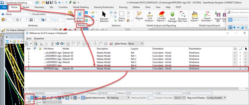
Table of Contents
TABLE OF CONTENTS.............................................................................................................................................. 3
    OBJECTIVES ...................................................................................................................................................................5
    INTRODUCTION ..............................................................................................................................................................5
    DOCUMENT STYLE ..........................................................................................................................................................6
1      POND DESIGN ................................................................................................................................................ 7
    OBJECTIVES ...................................................................................................................................................................7
    EXERCISE OVERVIEW .......................................................................................................................................................7
               Exercise 1.1         Create The Pond Design File .................................................................................................................... 7
               Exercise 1.2         Create The Pond Control Line ................................................................................................................ 10
               Exercise 1.3         Place A Pond Design Linear Template ................................................................................................... 20
               Exercise 1.4         Manipulate Pond Dimensions And Elevations ....................................................................................... 23
               Exercise 1.5         Create A Pond Design Surface ............................................................................................................... 26

2      STORMWATER FACILITIES SHEET .................................................................................................................. 27
    OBJECTIVE ...................................................................................................................................................................27
    EXERCISES OVERVIEW ....................................................................................................................................................27
               Exercise 2.1         Create The Stormwater Facilities Detail Sheet ...................................................................................... 28
               Exercise 2.2         Cutting Pond Sections............................................................................................................................ 33
               Exercise 2.3         Placing Special Details ........................................................................................................................... 45
               Exercise 2.4         Cutting Control Structure Sections ........................................................................................................ 50
               Exercise 2.5         Control Structure Form ......................................................................................................................... 55

FDOTCONNECT for ORD Workflows                                                     ©2021 FDOT                                                                                            3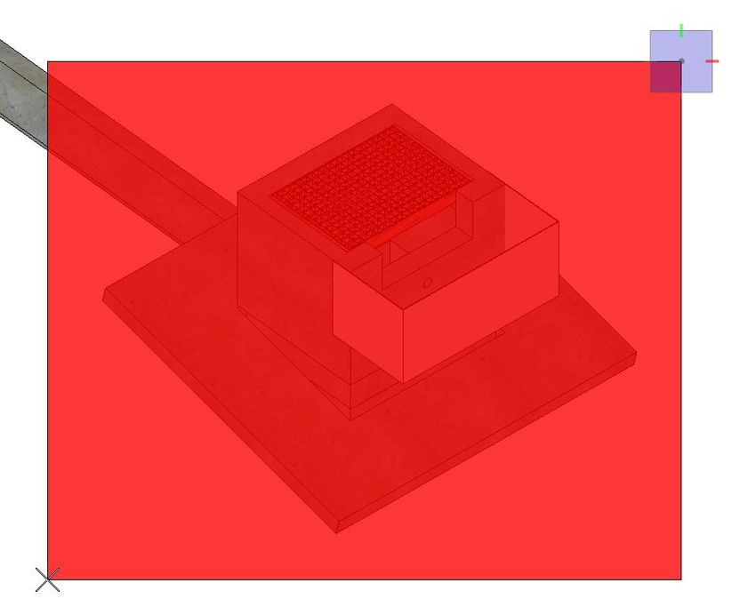
[PAGE INTENTIONALLY LEFT BLANK.]

FDOTCONNECT for ORD Workflows             ©2021 FDOT               4
OpenRoads Designer Pond Design
OBJECTIVES
    The objective of this manual is to provide the user with a general understanding of Open Roads Designer
    Technology that can be used to design and model drainage ponds. It also will demonstrate the basic plans
    production procedures for creating the Stormwater Facilities Sheet as per FDM 917. It will not attempt to instruct
    on proper engineering methodologies for pond design. That is beyond the scope of this manual.

INTRODUCTION
        OpenRoads Designer CONNECT Edition is the common technology for Bentley Systems civil products that
        has been developed in partnership with users. It combines data acquisition/survey, geometry corridor, terrain
        modeling, dynamic sections, and much more into a comprehensive set of tools within a common footprint.
        The FDOTConnect Workspace and tolls used in the exercises were developed to aide users in completing
        FDOT Projects on the ORD Connect platform to meet FDOT Standards.

FDOTCONNECT for ORD Workflows                       ©2021 FDOT                                                      5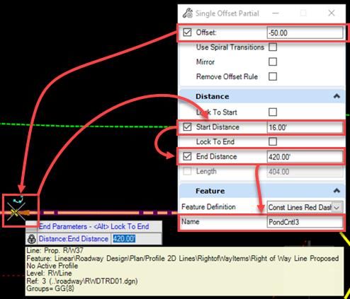
DOCUMENT STYLE
    Style conventions used throughout the course guide are shown in the following table.

           Item                     Convention                Example

       Menu names and        Bold N                      •    File > Open
       commands
                             (Names separated with >     •    File > ComSelect > Design
                             symbol)

       Dialog box Actions    Bold                        •    Click the Apply button.
                                                         •    Click the Graphic Select button to the right
                                                              of the Horizontal Alignment Include box.
                                                         •    In the Segment Type list, click Lines.

       Dialog box Field      Italic                      •    Key in Hemfield Road in the Alignment
       Names                                                  Name field.
                                                         •    Click the Graphic Select button to the right
                                                              of the Horizontal Alignment Include field.
                                                         •    In the Segment Type list, click Lines.

       Key-ins               Bold                        •    Key in Hemfield Road in the Alignment
                                                              Name field.

       File Names            Italic                      •    Open the file ALGNRD01.dgn in the
                                                              C:\WorkSets\FDOT\22049555201\Roadway.

       File Paths            Non italic                  •    Open the file _Blank.dgn in the
                                                              C:\WorkSets\FDOT\22049555201

       New Terms or          Italic                      •    The Template Library contains templates,
       Emphasis                                               which represent typical sections of the
                                                              proposed roadway.

    Additionally, a new workflow terminology using the Ribbon is used throughout the course guide. If you see a
    direction like this:
    DRAINAGE AND UTILITIES > LAYOUT > LAYOUT > Place Node
    This means we are in the Workflow of Drainage and Utilities which has a Tab named Layout and has tools
    that are located in the Layout Group. Now that we are in the right workflow, Tab and Group we may need to
    click on a tool that has more than one option.

FDOTCONNECT for ORD Workflows                      ©2021 FDOT                                                 6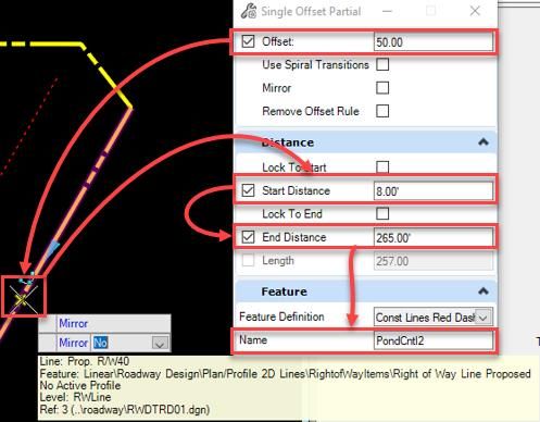
1              Pond Design
OBJECTIVES

EXERCISE OVERVIEW
        Exercise 1.1   Create The Pond Design File .................................................................................................................... 7
        Exercise 1.2   Create The Pond Control Line .................................................................................................................. 9
        Exercise 1.3   Place A Pond Design Linear Template ................................................................................................... 18
        Exercise 1.4   Manipulate Pond Dimensions And Elevations ....................................................................................... 22
        Exercise 1.5   Create A Pond Design Surface ................................................................... Error! Bookmark not defined.

Exercise 1.1 Create The Pond Design File

           From the desktop FDOTConnect folder double left click on the FDOTConnect for OpenRoads
           Designer icon. Make sure to set the Workspace to FDOT and the Workset to 22049555201_CE. Open
           the _BlankFile.dgn or any dgn file within the 22049555201_CE Workset.

FDOTCONNECT for ORD Workflows                                       ©2021 FDOT                                                                                         7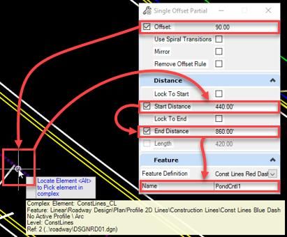
From the OpenRoads Modeling Workflow, navigate to the FDOT Tab of the Ribbon, then the
           Actions Group and left click on the Create File icon.

           The Create File dialog displays. On the Create File dialog, set the Discipline to Drainage and the File
           Group to Drainage Design Files. From the File Type list, select PDPLRD Pond Design. On the Output
           File section of the dialog, be sure to set the County to Wakulla and the Coordinate System to FL83-NF.
           Once everything is set up to match the image below, left click the Create – Open File button to create
           and open the Pond Design file. Now left click on the Close button to close the dialog.

FDOTCONNECT for ORD Workflows                    ©2021 FDOT                                                     8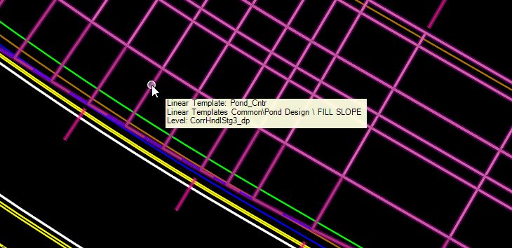
Navigate to the Home tab and in the Primary Group left click on the Attach Tools icon to open the
           References dialog.

           This will open the References dialog. Left click on the Attach References button in the upper left of
           the dialog. Navigate to and reference in the following design files:

               ✓   C:\worksets\FDOT\22049555201_CE\roadway\ ALGNRD01.dgn
               ✓   C:\worksets\FDOT\22049555201_CE\roadway\ DSGNRD01.dgn
               ✓   C:\worksets\FDOT\22049555201_CE\roadway\RWDTRD01.dgn
               ✓   C:\worksets\FDOT\22049555201_CE\survey\ GDTMRD01.dgn
               ✓   C:\worksets\FDOT\22049555201_CE\survey\ SURVRD01.dgn

           The pond will be constructed in the area of the proposed R/W to the right of SR61.

FDOTCONNECT for ORD Workflows                    ©2021 FDOT                                                   9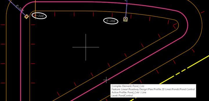
Exercise 1.2    Create The Pond Control Line
    Use the Roadway and R/W Lines to Create a Pond Boundary.

           Verify that the workflow is set to the OpenRoads Modeling Workflow and on the Home Tab in the
           Primary Group click on the Attach Tools icon. This will open the References dialog box. In the
           References dialog box left click on the SURVRD01.dgn reference file in the list and un-check the
           Display option to turn this file off for now.

           Construction lines will be used to create the Pond Control line. Setting ORD to use the Active Feature
           Definition will make things a little more streamlined. Left click on the Use Active Feature button.

            Now left click on the Feature Definition drop down. Expand the Linear folder then the Roadway Design
           folder followed by the Plan/Profile 2D Lines folder and the Construction Lines folder. Select Const Lines
           Red Dash feature definition from the list.

FDOTCONNECT for ORD Workflows                     ©2021 FDOT                                                     10
Under the Geometry tab in the Horizontal group, left click on the Offsets and Tapers dropdown and
select the Single Offset Partial tool.
This will open the Single Offset Partial dialog box. Check the box to lock the Offset. Type 90 in the
Offset field and hit Enter on the keyboard. Now left click (Data Point) on the Centerline of the roadway.
Check the box to lock the Start Distance. Type 70440 in the Start Distance field and hit Enter on the
keyboard. Now check the box to lock the End Distance. Type 70860 in the End Distance field and hit
Enter on the keyboard. Left click in the Name field and type PondCntl1. Hit Enter on the keyboard. Now
left click (Data Point) in the open 3 times to create the first Pond Control construction line.
FDOTCONNECT for ORD Workflows ©2021 FDOT 11Using the same tool, Change the Offset value to -50 and hit Enter on the keyboard. Left click (Data
Point) on the horizontal proposed right of way line. Type 16 in the Start Distance field and hit Enter on
the keyboard. Type 420 in the End Distance field and hit Enter on the keyboard. Change the Name field
to PondCntl2 and hit Enter on the keyboard. Now left click (Data Point) in the open 3 times to create the
second Pond Control construction line.
FDOTCONNECT for ORD Workflows ©2021 FDOT 12Using the same tool, Change the Offset value to 50 and hit Enter on the keyboard. Left click (Data Point)
on the diagonal proposed right of way line at the bottom of the two other Pond Control construction
lines. Type 8 in the Start Distance field and hit Enter on the keyboard. Type 265 in the End Distance
field and hit Enter on the keyboard. Change the Name field to PondCntl3 and hit Enter on the keyboard.
Now left click (Data Point) in the open 3 times to create the third Pond Control construction line.
There should be 3 red dashed lines placed inside the proposed R/W.
FDOTCONNECT for ORD Workflows ©2021 FDOT 13Under the Geometry tab in the Horizontal group left click on the Arcs dropdown and while hovering on
the Arc Between Elements flyout left click on the Simple Arc tool. This will open the Simple Arc dialog
box.
Set the Trim/Extend dropdown to Both. Check the Radius check box to lock the radius and type
25 in the field and hit Enter on the keyboard. Leave the Loop check box un-checked. Change
the Name field to PondCntlArc1 and hit Enter on the keyboard. Left click (Data Point) on the
PondCntl1 line and then left click (Data Point) on the PondCntl2 line. Left click (Data Point) 2
times in the middle of the proposed pond area to create the first arc.
FDOTCONNECT for ORD Workflows ©2021 FDOT 14Change the Name field to PondCntlArc2 and hit Enter on the keyboard. Left click (Data Point) on the
PondCntl2 line and then left click (Data Point) on the PondCntl3 line. Left click (Data Point) 2 times in
the middle of the proposed pond area to create the second arc. Now change the Name field to
PondCntlArc3 and hit Enter on the keyboard. Left click (Data Point) on the PondCntl3 line and then left
click (Data Point) on the PondCntl1 line. Left click (Data Point) 2 times in the middle of the proposed
pond area to create the third arc. There should now be an outline of the Pond Control shape.
Left click on the Feature Definition dropdown. Collapse the Construction Lines folder and expand the
Ponds folder. Select Pond control feature definition from the list.
FDOTCONNECT for ORD Workflows ©2021 FDOT 15Under the Geometry tab in the Horizontal group left click on the Complex Geometry dropdown and left
click on the Complex By Element. This will open the Create Complex By Element dialog box.
Set the Method to Automatic and the Maximum Gap to 0.01. Change the Name to PondCntl and hit
Enter on the keyboard.
Left click (Data Point) on the PondCntl1 construction line and Left click (Data Point) in the open below
the line to accept the new Pond Control complex element. Now hit the Esc key on the keyboard to
terminate the command.
FDOTCONNECT for ORD Workflows ©2021 FDOT 16Zoom out so the Existing Ground Boundary is visible. Using the element selector tool, left click (Data
Point) on the green dashed Existing Ground Boundary Element. Hover over the line to cause the pop-up
menu to appear. Select the middle icon to set this as the Active Terrain Model and left click (Data Point)
in the open to clear the selection set.
Using the element selector tool again, select the Pond Control shape. Hover over the selected shape and
choose the second icon to Open a Profile Model of the existing ground along the Pond shape.
Now left click on the Open or Close a View button for view 4 and left click (Data Point) inside the newly
open view 4 window. This will create a Profile view of the Existing Ground surface along the Pond
Control Shape.
FDOTCONNECT for ORD Workflows ©2021 FDOT 17Under the Geometry tab in the Vertical group left click on the Element Profiles dropdown and left click
on the Profile By Constant Elevation tool. This will open the Create Element By Elevation dialog box.
Set the Elevation to 33 and the Name to PondCntlProf1. With view 1 active left click (Data Point) on
the Pond Control shape to select it and right click in the open to accept it.
Now left click (Data Point) one more time to create the new Pond Control Profile. It will appear in the
view 4 Profile view as a flat line at an elevation of 33 feet. Hit the Esc key on the keyboard to exit this
tool.
Now left click (Data Point) two times in view 4 to activate it. Using the Element Selector tool, select the
new Pond Control Profile line. Hover over the Pond Control Profile line until the context menu pops up
and move the cursor to the second icon. Left click (Data Point) to set this as the Active Profile. Now left
click (Data Point) in the open to clear the selection set.
FDOTCONNECT for ORD Workflows ©2021 FDOT 18FDOTCONNECT for ORD Workflows ©2021 FDOT 19
Exercise 1.3 Place A Pond Design Linear Template

           In preparation for the use of a Linear Template later in this exercise, it is necessary to make sure the
           proper Template Library is available. Choose the Corridors tab and in the Create Group left click on
           the Create Template tool. The Create Template dialog box will open. On this dialog left click on the
           File menu and choose the Open option. This will open the Open File dialog.

           In the Open File dialog navigate to the Rodway folder of the current Project folder and select the
           22049555201_CE.itl file. Now left click on the Open button in the lower right corner of the dialog box.

FDOTCONNECT for ORD Workflows                      ©2021 FDOT                                                     20
On the Create Template dialog box in the Template Library list, open the Linear Templates Common
folder and double left click on the Pond Design linear template. The Current Template field should
now be Pond Design. Left click on the Close button in the upper right corner of the dialog box.
Now left click on the Use Active Feature Definition button next to the Feature Definition drop down to
deactivate this setting.
FDOTCONNECT for ORD Workflows ©2021 FDOT 21Change to the Model Detailing tab and in the 3D Tools group left click on the Apply Linear Template
tool. This opens the Apply Linear Template dialog box.
On this dialog make sure that only the Lock To Start, Lock To End and Exterior Corner Sweep Angle
check boxes are checked. The Exterior Corner Sweep Angle should be set to 5 degrees and the Template
should be set to Linear Templates Common\Pond Design. The Description field should be set to
PondCntlSurf1. The Feature Definition should be set to Final and the Name should be set to
PondCntlSurf1. Now left click (Data Point) on the lower right corner of the Pond Control shape and left
click (Data Point) in the center of the shape 6 times to apply the Pond Design Linear template. Hit the
Escape key to close the Apply Linear Template dialog box and exit the tool.
With view 1 active right click and hold until the pop-up menu appears. Hover over the View Control
flyout and choose the 2 Views Plan/3D option.
FDOTCONNECT for ORD Workflows ©2021 FDOT 22Exercise 1.4 Manipulate Pond Dimensions And Elevations
The example Pond’s fill slope extends too far and is encroaching on the proposed sidewalk. Fixing this
will be simple and easy to do. First thing to do, is to make it easier to see what can be changed by turning
off the 3D view reference in the 2D view. Make sure that the 2D view, view 1 is the active view. Zoom
to the side if the proposed roadway design that runs alongside the Pond fill slope. There is a portion of
the proposed sidewalk that is covered by the Pond fill slope.
Under the Home tab in the Primary group left click on the Attach Tools icon. This will open the
References dialog box. Find the Default-3D model reference and select it. Now just turn off the display
by either removing the check mark under the Display column or left clicking on the Display button in
the bottom left corner of the dialog. Close the References dialog box.
FDOTCONNECT for ORD Workflows ©2021 FDOT 23Zoom view 1 out so the entire Proposed pond is visible. Left click (Data Point) on the Pond Control line
to see all its parameters that can be changed in the 2D plan view. Dimensions, angles, bearings, offsets
and even the radius of the arcs can be manipulated in this view.
Open and activate view 4, the profile view. This is the view that will be used to change the elevation of
the Pond Control Profile to fix the encroachment issue with the proposed sidewalk. Use the Element
Selector to left click (Data Point) on the Pond Control profile line. Once selected there will be a value of
33 feet located near the center of the profile line. Left click on the number and enter the change in the
field provided next to the cursor. Type in 31 and hit the Enter key on the keyboard. The level of the Pond
Control Profile will update.
FDOTCONNECT for ORD Workflows ©2021 FDOT 24Activate view 1, the 2D plan view and reopen the References dialog box by hitting the F9 key on your
keyboard. Select the Default-3D model reference. Now just turn on the display by either left clicking to
replace the check mark under the Display column or left clicking on the Display button in the bottom
left corner of the dialog. Close the References dialog box.
Left click (Data Point) in view 1 and zoom in close to where the problem was with the fill slope. The fill
slope no longer encroaches on the proposed sidewalk.
FDOTCONNECT for ORD Workflows ©2021 FDOT 25Exercise 1.5 Create A Pond Design Surface
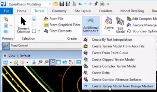
Using the OpenRoads Modeling Workflow under the Terrain tab in the Create group left click on the
Additional Methods dropdown and select the Create Terrain Model from Design Meshes option. The
Create Terrain Model from Design Meshes dialog opens.
Set the Select Side Of Closed Mesh dropdown to Top. Set the Design Surface Feature Definition
dropdown to DtmProposedPond. Check the Rule Exterior check box. Set the Exterior Feature Definition
dropdown to No Feature Definition. Check the Rule Void check box. Set the Void Feature Definition
dropdown to Pond Bottom. Set the Void Minimum Area field to 0.
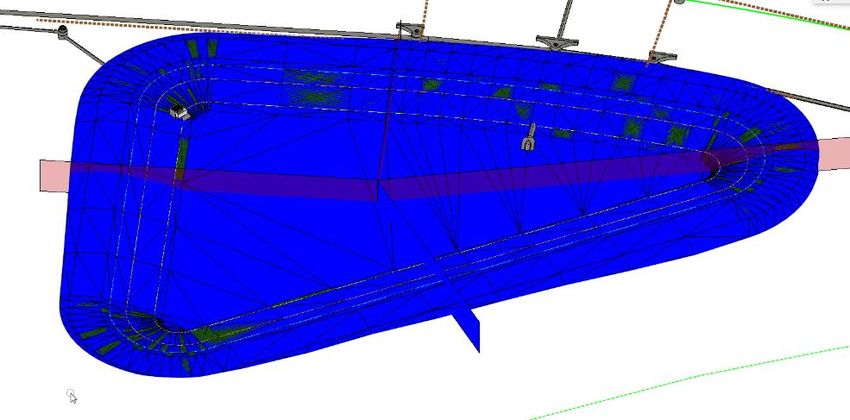
Left click (Data Point) on the fill slope area of the proposed pond and then left click (Data Point) in the
open 6 more times to complete the command. It will take a few seconds, but the new terrain element will
appear, including the pond bottom that was not present before.
FDOTCONNECT for ORD Workflows ©2021 FDOT 262 Stormwater Facilities Sheet
OBJECTIVE
The objective of this chapter is to demonstrate the basic plans production procedures for laying out the
Stormwater Facilities Detail Sheet as per FDM 917.
EXERCISES OVERVIEW
Exercise 2.1 Create The Stormwater Facilities Detail Sheet ...................................................................................... 28
Exercise 2.2 Cutting Pond Sections............................................................................................................................ 33
Exercise 2.3 Placing Special Details ........................................................................................................................... 45
Exercise 2.4 Cutting Control Structure Sections ........................................................................................................ 50
Exercise 2.5 Control Structure Form ......................................................................................................................... 55
FDOTCONNECT for ORD Workflows ©2021 FDOT 27Exercise 2.1 Create The Stormwater Facilities Detail Sheet
From the desktop FDOTConnect folder double left click on the FDOTConnect for OpenRoads
Designer icon. Make sure to set the Workspace to FDOT and the Workset to 22049555201_CE. Open
the PDPLRD01.dgn file within the 22049555201_CE Workset.
FDOTCONNECT for ORD Workflows ©2021 FDOT 28In order to create the Stormwater Facilities Detail Sheet the DRPRRD00.dgn file will need to be
referenced. Verify the Workflow is OpenRoads Modeling and the focus is on view 1. From the Home
tab in the Primary group left click on the Attach Tools icon to open the References tool dialog.
Using the References dialog attach the DRPRRD00.dgn file in the Drainage folder of the current project.
Now turn off the view of the Default-3D reference by selecting it in the list and left clicking on the view
button in the lower left corner of the dialog. Close the References dialog. Other drainage elements of
this project will now be visible.
Left click on the Rotate View tool in the view controls bar. Select the Two points method in the Rotate
View dialog box. For the first point, snap to the end of the Minor Tic Mark nearest to station 704 of the
roadway centerline alignment. Left click (Data Point) to accept. For the second point, snap to the next
Minor Tic Mark and left click (Data Point) to accept. The view will rotate to a more useful orientation
for sheet creation.
.
FDOTCONNECT for ORD Workflows ©2021 FDOT 29Go to the Drawing Production tab and in the Named Boundary group left click on the Named
Boundary dropdown. Select the Place Named Boundary tool to open the Place Named
Boundary dialog box.
Choose the Civil Plan option and left click on the Drawing Seed dropdown. Select the 36x48 Plan Only
option from the list. Now left click on the Detail Scale dropdown and choose 1” = 20’. Now set the Name
field to Pond 1 and the Description field to Pond Plan View. The Group dropdown will automatically be
set to (New). Using the Tab key on the keyboard, tab down until the second Name field is highlighted.
Now select the Roadway Alignment element in view 1. The current Name field will change to CL_SR61,
the name of the Roadway Alignment. Tab to the Description field and type in Stormwater Facility Detail
Sheet. Check both the Start Location and Stop Location check boxes. Set the Start Location field to
70400 and the Stop Location field to 70920. Set the Length field to 520. The Left Offset field should be
set to 0 and the Right Offset field should be set to 400. Set the Overlap field to 0 and the Boundary
Chords field to 5. Make sure the check boxes for Create Drawing and Show Dialog are checked. Left
click (Data Point) in open space in view 1 to see a preview of the boundary. Left click (Data Point) again
in open space to accept this boundary and the Create Drawing dialog box will open.
FDOTCONNECT for ORD Workflows ©2021 FDOT 30Make sure the Mode dropdown is set to Plan and the Name field is set to Pond 1. Verify that the Drawing
Seed dropdown and the Drawing Boundary dropdown both say 36x48 Plan Only. Finally, the Detail
Scale dropdown should read 1” = 20’ by named boundary. With all this set, left click on the Ok button
to create the Pond 1 Sheet Views with a Pond 1 Sheet sheet model and the Pond 1 Views with a Pond 1
design model.
The program will now open the Pond 1 sheet view for review. Switch back to the Home tab and in the
Primary group left click on the Attach Tools icon to bring up the References dialog.
FDOTCONNECT for ORD Workflows ©2021 FDOT 31In the References dialog select the Pond 1 Model. Choose the Move command from the button bar and
left click (Data Point) in the middle of the proposed pond. Move the reference to the upper left corner of
the sheet and left click (Data Point) to accept the move. Close the References dialog and switch back to
the Multi-Model view.
FDOTCONNECT for ORD Workflows ©2021 FDOT 32Exercise 2.2 Cutting Pond Sections
Change the Active Workflow to the Drawing Workflow and select the Home tab. In the Attributes group
left click on the Active Level dropdown and choose PatternLines1_dp from the list.
Draw a line to use as a start point for the section pattern lines. Click the Place Line tool. Now using the
Center Snap option Tentative click on the PondCntl shape.
.
Left click (Data Point) to start drawing the temporary line. Move the cursor to the lower left and left
click (Data Point) to complete drawing the temporary line.
FDOTCONNECT for ORD Workflows ©2021 FDOT 33Using the temporary line as a start point, draw a line going straight up ending just past the BSW2 line.
Once again, start drawing a line at the upper end of the temporary line. Using the Perpendicular snap
option, Snap on the yellow property line to the lower right, left click (Data Point) to finish the line.
The next line will start at the upper end of the temporary line and run horizontal extending to the left, so
Snap to and left click (Data Point) on the upper end of the temporary line. Drag to the left and press the
Enter key on the keyboard to lock AccuDraw to the Horizontal Axis. Tentative click on the vertical
yellow property line to the left of the pond and left click (Data Point) to complete the line.
FDOTCONNECT for ORD Workflows ©2021 FDOT 34The final line needed will go from the upper end of the temporary line through the upper right corner of
the pond and extend just shy of the SidewalkBack line. There is a small bit of setup to make this line
much easier to draw, with the Place Line command active change to the Drawing Aids tab. Left click
(Data Point) on the upper end of the temporary line to start drawing the line and tentative click on the
midpoint of the Pond_Cntr arc in the upper right corner of the pond.
Switch to the AccuDraw section of the Drawing Aids tab and click on Set Origin. Next press R then
Q on the keyboard to begin to rotate AccuDraw. Snap back to the upper end of the temporary line and
Left click (Data Point) on it. This will orient AccuDraw to the proper angle as shown below.
FDOTCONNECT for ORD Workflows ©2021 FDOT 35Once this is done, move the cursor up and right just past the AccuDraw Origin and press the Enter key
on the keyboard to lock the direction of the line being drawn. Now left click (Data Point) near the green
SidewalkBack line to the upper right of Pond 1 to complete this line.
All the pattern lines are now drawn. Delete the temporary line. View 1 should look like the picture below
once the temporary line is deleted.
Switch back to the OpenRoads Modeling Workflow and click on the Drawing Production tab. Then
click on Place Named Boundary tool in the Named Boundaries group.
This will bring up the Place Named Boundary dialog box. Click on the Civil Cross Section 2 Points
tool.
FDOTCONNECT for ORD Workflows ©2021 FDOT 36Set the values in the dialog as shown below.
The dialog is now waiting on a Path Element to be identified. Left click (Data Point) on the vertical
pattern line. Then tentative click on the top end of the line and left click (Data Point) to accept this as
the First Point. Next tentative click on the other end of the line and left click (Data Point) to accept this
as the Second Point. Finally left click (Data Point) in open space near the line to accept the selection.
The Create Drawing dialog now appears. Most of the settings on this dialog will be set correctly when
it appears, but check all of them against the image below and set any values that differ to the values
provided. The dropdown value for Sheets will need to be set to Pond 1 [Sheet].
FDOTCONNECT for ORD Workflows ©2021 FDOT 37Click the Ok button.
This will process the section and open the Pond 1 [Sheet]. The new section will be located as shown in
the image below. It will need to be moved using the Reference File tools.
Click on the Home tab. Then click on the Attach Tools in the Primary group to bring up the References
dialog box. Choose the newly created reference for the section and click on the Move Reference tool.
FDOTCONNECT for ORD Workflows ©2021 FDOT 38Now left click (Data Point) in the reference boundary for the new section and move it below the Plan
View boundary and close to the left edge of the sheet similar to the example below.
Once again change back to the Multi-Model Views View Group.
Switch to the Drawing Production tab and click on the Place Named Boundary tool once again to
bring up the Place Named Boundary Civil Cross Section dialog. Set all values as indicated below, be
sure the Backwards facing checkbox is checked. In View 1 select the lower pattern line and Snap to the
top point of that line. Left click (Data Point) to accept the First Point. Now Snap to the other end of the
pattern line and left click (Data Point) to accept the second point. Left click (Data Point) in the open to
finish the command.
The Create Drawing dialog now appears. Most of the settings on this dialog will be set correctly when
it appears, but check all of them against the image below and set any values that differ to the values
provided. The dropdown value for Sheets will need to be set to Pond 1 [Sheet].
FDOTCONNECT for ORD Workflows ©2021 FDOT 39Click the Ok button.
This will process the section and open the Pond 1 [Sheet] Model. The new section will be located as
shown in the image below. It will need to be moved using the Reference file tools.
Click on the Home tab. Then click on the Attach Tools in the Primary group to bring up the References
dialog box. Choose the newly created reference for the section and click on the Move Reference tool.
Now Snap to the left end of the pond bottom of the new section and move it to align with the first section
as shown in the example below.
FDOTCONNECT for ORD Workflows ©2021 FDOT 40The Pond 1 [Sheet] should now look like this example.
Change back to the Multi-Model Views View Group.
Switch to the Drawing Production tab and click on the Place Named Boundary tool once again to
bring up the Place Named Boundary Civil Cross Section dialog. Set all values as indicated below. In
View 1 select the left most pattern line and Snap to the left end of that line. Left click (Data Point) to
accept the First Point. Now Snap to the other end of the pattern line and left click (Data Point) to accept
the Second Point. Left click (Data Point) in the open to finish the command.
FDOTCONNECT for ORD Workflows ©2021 FDOT 41The Create Drawing dialog now appears. Make sure that the dropdown value for Sheets is set to
Pond 1 [Sheet].
Click the Ok button.
This will process the section and open the Pond 1 [Sheet] Model. The new section will need to be moved
using the Reference file tools to the location below.
Change back to the Multi-Model Views View Group.
FDOTCONNECT for ORD Workflows ©2021 FDOT 42Switch to the Drawing Production tab and click on the Place Named Boundary tool once again to
bring up the Place Named Boundary Civil Cross Section dialog. Set all values as indicated below. In
View 1 select the remaining pattern line and Snap to the left most end of that line. Left click (Data Point)
to accept the First Point. Now Snap to the other end of the pattern line and left click (Data Point) to
accept the Second Point. Left click (Data Point) in the open to finish the command.
The Create Drawing dialog now appears. Make sure that the dropdown value for Sheets is set to
Pond 1 [Sheet].
Click the Ok button.
FDOTCONNECT for ORD Workflows ©2021 FDOT 43This will process the section and open the Pond 1 [Sheet] Model. The new section will need to be moved
using the Reference file tools to the location below. When done the Pond 1 [Sheet] Model should look
like the example below.
FDOTCONNECT for ORD Workflows ©2021 FDOT 44Exercise 2.3 Placing Special Details
Continuing in the PDPLRD01 file, make sure that the Default-3D Views is the active View.
Using the Rotate View tool’s Rotate 3D method, rotate and zoom the view until it is similar to the one
below.
Using the OpenRoads Modeling Workflow go to the Primary Group and select the Level Display
tool. This will open the Level Display dialog. Highlight the PDPLRD01.dgn file in the file list. Turn
off all but the active level in this file. Close the dialog box. The view should look like the one below.
FDOTCONNECT for ORD Workflows ©2021 FDOT 45Now zoom in to the structure to be detailed.
Change to the Drawing Production tab and select the Clip Volume tool.
The Create Clip Volume dialog will display now. Select the Apply Clip Volume By 2 Points tool.
Make sure the Display Clip Element checkbox is unchecked.
FDOTCONNECT for ORD Workflows ©2021 FDOT 46Left click (Data Point) in open space and drag down and left to create a Clip Volume like the example.
Now click on the icon to Create Named Boundary From Clip Volume. Name it SpecialDetail.
Open the Saved Views dialog by clicking in the lower right corner of the Saved Views group of the
Drawing Production tab.
FDOTCONNECT for ORD Workflows ©2021 FDOT 47On the Saved Views dialog click the Create Saved view icon in the upper left of the dialog box.
Set the values of the Create Saved View dialog box as follows.
FDOTCONNECT for ORD Workflows ©2021 FDOT 48Close the dialog and change to the Pond 1 [Sheet] Views View Group. Open the References dialog
from the Primary group on the Home tab. Click on the Attach Reference icon in the upper left of the
dialog box. This will bring up the Attach Reference dialog. Choose the PDPLRD01.dgn file in the list
and click the Open button. Set the values in the Reference Attachment Properties dialog box as
follows and click the Ok button to accept.
FDOTCONNECT for ORD Workflows ©2021 FDOT 49Now place the Reference in the upper right corner of the Pond 1 [Sheet] Views. The sheet should now
look like the image below.
Exercise 2.4 Cutting Control Structure Sections
Continuing in the PDPLRD01.dgn file, switch to the Drawing Workflow. While in the Multi-Model
Views View Group make View 1 active and click on the Rotate View icon. Using the 2 Points Method
tentative click on the end of the red dashed line in the center of the 2D structure as shown.
FDOTCONNECT for ORD Workflows ©2021 FDOT 50Now Snap to the midpoint of the tan line to the right as shown and click to complete the view rotation.
Using Place Line tool from the Placement group on the Home tab. Tentative click on the end of the red
dashed line. Switch to the Drawing Aids tab and choose the Set Origin tool in the AccuDraw group.
Move the cursor horizontally to the left and press the Enter key on the keyboard to lock the Axis of
AccuDraw. Type the number 8 on the keyboard and left click (Data Point) to start drawing the pattern
line. Move the cursor horizontally to the right and press the Enter key to lock the axis. Type the number
16 on the keyboard and left click (Data Point) to finish placing the pattern line.
Once again, use the Place Line tool on the Home tab. Tentative click on the end of the red dashed line.
Switch to the Drawing Aids tab and click on the Set Origin tool. Move the cursor vertically up from
the end of the line and press the Enter key to lock the Axis to vertical movement. Type the number 6
and left click (Data Point) to start drawing the pattern line. Move the cursor down through the center of
the 2D structure. Press the Enter key to lock the Axis to vertical movement and type the number 12.
Left click (Data Point) to complete the pattern line. The structure should look like the example below.
FDOTCONNECT for ORD Workflows ©2021 FDOT 51Switch back to the OpenRoads Modeling Workflow. Use the Place Named Boundary tool to bring
up the Place Named Boundary Civil Cross Section 2 Points dialog. Set the values as shown.
Select the horizontal pattern line and Snap to the left end of the line. Left click (Data Point) to accept
the First Point. Now Snap to the right end and left click (Data Point) to accept the Second Point. Finally
left click (Data Point) in the open to bring up the Create Drawing dialog. Set the values as shown.
This will process the section and open the Pond 1 [Sheet] Views Group. The new section will be
located as shown in the image below. It will need to be moved using the Reference File tools.
FDOTCONNECT for ORD Workflows ©2021 FDOT 52Using the References Move Reference tool, move the new section to the location just below the Special
Detail in the upper right of the Pond 1 [Sheet] Views, as shown below.
Switch back to the Multi-Model Views View Group and make View 1 active. Use the Place Named
Boundary tool to bring up the Place Named Boundary Civil Cross Section 2 Points dialog. Set the
values as shown.
FDOTCONNECT for ORD Workflows ©2021 FDOT 53Select the vertical pattern line and Snap to the top end of the line. Left click (Data Point) to accept the
First Point. Now Snap to the bottom end and left click (Data Point) to accept the Second Point. Finally,
left click (Data Point) in the open to bring up the Create Drawing dialog. Set the values as shown.
This will process the section and open the Pond 1 [Sheet] Views Group. The new section will be located
as shown in the image below. It will need to be moved using the Reference
File tools.
Using the References Move Reference tool, move the new section to the location just below the Special
Detail in the upper right of the Pond 1 [Sheet] Views, as shown below.
FDOTCONNECT for ORD Workflows ©2021 FDOT 54Exercise 2.5 Control Structure Form
Continuing in the PDPLRD01.dgn file, switch to the Pond 1 [Sheet] Views Group and open the FDOT
tab.
Click on the Linked Data Manager tool in the Actions group.
This will bring up the FDOT Linked Data Manager dialog. Click on the Create new link button in
the upper left corner of the dialog.
FDOTCONNECT for ORD Workflows ©2021 FDOT 55On the Link Information dialog box click the Create New from Template button.
This will open the Select FDOT Template dialog box. Click on the dropdown menu and choose Misc
Boxes.
Now select Stormwater Facility Control Structure from the list of templates and click the Ok button
to save the newly created file to the Drainage directory of the current project.
Type Stormwater Facility Control Structure form for Pond 1 in the Description and set the
Worksheet dropdown to Sheet 1.
FDOTCONNECT for ORD Workflows ©2021 FDOT 56Set the remainder of the dialog as shown below and click the Ok button to begin placement of the
Control Structure form.
It will take a bit of time for the program to create the new blank Excel file and then begin the process for
the placement of the form in the drawing, so be patient. Eventually you will have a form attached to the
cursor to be places. Move it near the location show below and left click (Data Point) to place.
Back in the FDOT Linked Data Manager dialog, select and right click on the entry for the new form.
Select Open Source from the list. This will open Excel and allow editing of the new blank form.
Fill out the form and hide unused columns as shown in the example below. Once edits are made save the
file and close Excel.
FDOTCONNECT for ORD Workflows ©2021 FDOT 57Finally, right click on the new form in the FDOT Linked Data Manager and choose Update Now. This
will update the placed version of the form to the latest saved version of the Excel file. Anytime a change
is needed follow these steps to update the form.
The Pond 1 [Sheet] View should now look like the following example.
FDOTCONNECT for ORD Workflows ©2021 FDOT 58You can also read