POWDER FEEDER FOR RH & DODECAGON DRUMS USER GUIDE - Bayer SeedGrowth
←
→
Page content transcription
If your browser does not render page correctly, please read the page content below
POWDER FEEDER FOR RH & DODECAGON DRUMS USER GUIDE

MENU                                                                                  This is an interactive PDF. Click on an
                                                                                              icon tile and navigate to a chapter of
                                                                                              interest.

Legal & Safety   RH Drum                  Dodecagon                             DDS Control                  Maintenance

                           Users can advance or go back single pages by using
 Pictograms                quick navigation links shown below, right.
                           Users can navigate to the Menu by clicking on the
                           Menu icon shown below, left.

                                                   2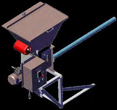
LEGAL & SAFETY
This manual contains technical information regarding Bayer SeedGrowth™ Equipment. Please read and understand these instructions
completely before proceeding to install and operate the equipment. Bayer reserves the right to change specifications, models,
components, or materials at any time without notice. For additional equipment information contact us at 1.800.634.6738. Please have
this manual available when contacting Bayer.

Always use caution and common sense when working with any chemical. Read the product label and SDS carefully and follow their
instructions exactly as described.

Optimal operating conditions for this piece of equipment requires an ambient temperature 32° F to +104° F (0° C to +40° C), relative
humidity less than 90% (minimum condensation). Make necessary provisions to protect this piece of equipment against excessive dust,
particles containing iron, moisture and against corrosive and explosive gases.

Our technical information is based on extensive testing and is, to the best of our current knowledge, true and accurate but given without
warranty as the conditions of use and storage are beyond our control. Variables, such as humidity, temperature, change in seed size
or variety and viscosity of chemical products can all affect the accuracy of the chemical application and seed coverage. To ensure the
desired application rate and optimum seed coverage, check the calibration periodically throughout the day, and make adjustments as
needed.

Any person who is involved in the installation or periodic maintenance of this equipment should be suitably skilled or instructed and
supervised using a safe system of work. Isolate the treater before removing guards for maintenance.

                                                                   3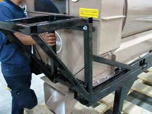
EXPOSURE CONTROL
Always use caution and common sense when working
with chemicals. Read the product label and SDS carefully                           Wear protective clothing                       Treatment products
and follow their instructions exactly as described.                                Wear disposable or reusable coveralls with     Keep products in a locked room that has
                                                                                   long sleeves.                                  been approved for crop protection products.
The following Personal Protective Equipment (PPE)
recommendations and best practices help promote                                    Hand protection required                       Wear a mask
safe use in seed treatment.
                                                                                   Wear chemical-resistant gloves.                Wear respiratory protection.

                                                                                   Wear rubber boots                              Eye protection required
                                                                                   Wear chemical resistant rubber boots.          Wear protective eyewear.

                                                                                   Labels                                         Calibration
                                                                                   Label recommendations and directions           Seed treatment equipment must be checked
                                                                                   for handling must be followed, including       and calibrated regularly to ensure accurate
      Note: Exposure Control signs and labels conform to the requirements of
                                                                                   treatment procedure (use of sticker) as well   and safe application.
      ANSI Z535.4 or ISO 3864.
                                                                                   as the safety requirements.

                                                                                   Clean seed                                     Empty containers
                                                                                   Use well cleaned seed to avoid creation        Non-returnable empty containers must be
                                                                                   of polluted dust that will contaminate the     triple rinsed before they can be disposed. For
                                                                                   machine, treating facility, workers, farmers   others the recommendation of the producer
                                                                                   and the environment during sowing.             must be followed.

                                                                                   Cleaning                                       Spillage
                                                                                   Use a vacuum to clean machines. Avoid          Spillage must be avoided; it must be
                                                                                   using compressed air for cleaning.             thoroughly cleaned up to avoid contaminating
                                                                                                                                  the environment and waterways.

                                                                                   Laundry                                        Maintenance
                                                                                   Wash soiled reusable clothing separately.      Keep machinery clean between
                                                                                   Workers must take a shower after each shift.   treating sessions.

                                                                               4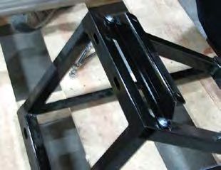
!           REFERENCE SYMBOLS
                                                                             Shock Hazard                                     Hand crush - moving parts
Symbols and signal words are used to identify the                            Alerts that dangerous voltage may be             Alerts crushing is possible.
level of hazard and help avoid personal injury.                              present.

                                                                             Warning                                          Pinch point

                                                                         !   Alerts that a hazard may cause serious
                                                                             injury or death.
                                                                                                                              Keep hands away from pinch points.

                                                                             Caution                                          Rotating shaft

                                                                         !
     Note: Safety signs and labels conform to the requirements of ANSI
     Z535.4 or ISO 3864.                                                     Alerts that a hazard may cause minor or          Do not wear loose clothing around turning
                                                                             moderate injury.                                 parts.

                                                                             Disconnect                                       Tools
                                                                             Disconnect to de-energize before opening.        Required tools for installation
                                                                                                                              and maintenance.

                                                                             Use guards                                       Parts
                                                                             Keep guards in place. Do not remove during       Required parts for installation
                                                                             operation.                                       and maintenance.

                                                                             Lifting                                          Tip
                                                                             Requires two people to safely lift an item.      Calls attention to special information.

                                                                             Lift points                                      Note
                                                                             Requires the use of proper rigging and lifting   Emphasizes general information worthy of
                                                                             techniques based on the lift plan.               attention.

                                                                             Center of gravity                                Example
                                                                             Indicates the center of gravity of the machine   Provides a problem or exercise that
                                                                             to help assist when rigging and lifting.         illustrates a method or principle.

                                                                             5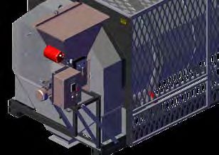
PICTOGRAMS                                                     Each Signifier displayed here is
                                                                  specific to this User Manual.

  Menu           Previous     Advance       RH Drum   Dodecagon Drum          DDS CONTROL

Powder Feeder   Cursor Hand    Like

                                        6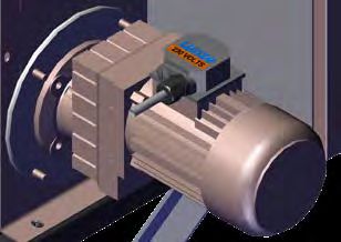
RH DRUM
Required installation tools
• Material Handling Device
• 1/2” Wrench (2)
• 1/2” Drill Bit Index
• Drill
• Petroleum Jelly
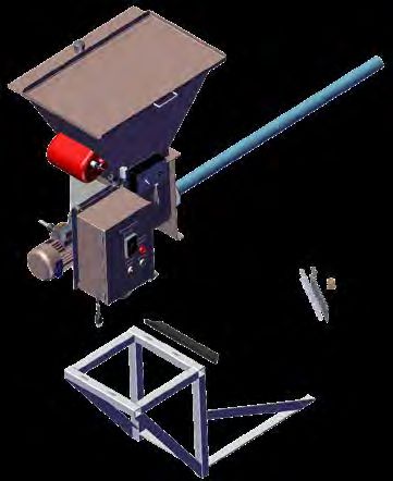
Optional Powder Feeder Assembly
Remove the Powder Feeder Assembly, Frame and Instal-
lation Kit from the shipping pallet and check for missing
or damaged parts.
Continued
Powder Feeder Assembly, ref.
Fastener Kit*
Installation bag #1 (leg braces)
• 5/16-18 x .75 hex bolt - zinc (2)
Installation Kit, ref.
• 5/16-18 x 2.00 hex bolt - zinc (2)
• 5/16-18 x 2.25 hex bolt - zinc (2)
• 5/16-18 x 2.75 hex bolt - zinc (2)
• 5/16-18 hex nut - zinc (8)
• 5/16-18 lock washer - zinc (8)
• 5/16-18 flat washer - zinc (12)
* Shipped in cloth bag
Frame, ref.
7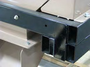
Step 1: Remove the Rubber Plug from the Doghouse.
Step 2: Apply petroleum jelly onto the backside of the Auger Tube Seal prior to inserting into the Doghouse (supplied from factory).
Step 3: Insert Auger Tube Seal into the Doghouse.
Step 4: Apply petroleum jelly onto the orifice of the Auger Tube Seal.
Continued
1 2 3
Remove Rubber Plug from Doghouse, ref. Apply Petroleum Jelly on the backside of the Auger Tube Seal, ref. Insert the Auger Tube Seal into the Doghouse, ref.
4
Apply Petroleum Jelly on Auger Tube Seal orifice, ref.
8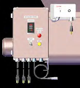
Step 5: Use 1/2” wrench to remove the existing 5/16-18 Step 6: Fasten the Powder/Doghouse Bracket to the Step 7: Have one person lift and hold the Support Frame
bolt from the bottom of the RH Drum Frame and set Powder Hopper Support Frame (as shown below) using in place and another align the Support Angle with the
removed hardware aside to be used later. two 5/16-18 x 2.25 Hex Bolts, Washers, Lock washers drilled holes on the Drum Frame.
and Nuts in the following order: bolt+flat washer+[spacer
plate+frame]+lock washer+nut. Tighten hardware.
Continued
Note: the orientation of the Bracket (facing down
towards bottom and in relation to the slot holes on
top of the Frame!
9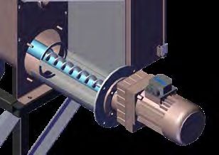
Step 8: Bolt in place with two 5/16-18 x 2.75 Hex Bolts, Step 9: Fasten the bottom of the Support Frame to the Step 10: Use a 5/16” drill bit. Drill two 5/16” holes in the
Washers, Lock washers and Nuts in the following order: Doghouse Frame (as shown below) using one 5/16-18 x Doghouse to connect the Powder/Doghouse Bracket to
bolt+flat washer+[frame]+lock washer+nut. 3.00 Hex Bolt, Washer and serrated Nut on the left side the Doghouse.
• Hand tighten hardware in place for now. and one 5/16-18 x 2.25 Hex Bolt, Washer and serrat- • Fasten the Powder/Doghouse Bracket to the Dog-
ed Nut on the right side in the following order: bolt+flat house with two 5/16-18 x .75 Hex Bolts, Washers and
washer+[spacer plate+frame]+lock washer+nut. serrated Nut in the following order: bolt+flat wash-
• Hand tighten hardware in place for now. er+[bracket+doghouse]+Serrated Nut.
• Tighten securely in place.
• Tighten all hardware used with the frame securely
in place.
Step 11: Remove shipping bolts that hold the Powder
Feeder Assembly onto the pallet.
Continued
10Step 12: Open the Powder Feeder Lid and connect rig- Step 13: Use an overhead hoist to lift the Powder Feeder
ging to each side. Assembly. 30cfm max. recommended.
• Use proper rigging and lifting techniques to ensure • Carefully insert the Auger Tube into the Auger Tube
safety when installing the Powder Feeder onto the RH Seal on the Doghouse Door Plate.
Drum & Frame Assembly.
• Approximate dry weight: 190lbs./ 86Kg. Integrated Aspiration System
An exhaust unit with slide gate supplied
by the customer must be connected to
a central aspiration system.
A 1.5” Dust Evacuation Port is available
on top of the Powder Feeder Hopper.
Connect to shop aspiration system.
Step 14: Connect the Powder Feeder Assembly to the
Powder Hopper Support Frame using four 5/16-18 x 2.50
Hex Bolt, Washer and serrated Nut and 1/2” socket.
• Align with the four drilled holes on the Powder Body.
Fasten in place with supplied hardware and in this
order: bolt+flat washer+[frame]+Serrated nut.
• Tighten securely in place.
Continued
11Electrical Connections
1. POWER Connect the Dry Delivery Control Box Power
START
POWER AUGER VIB STOP SENSOR Male Cord Grip (bottom of the Dry Delivery Control Box
marked POWER) to an external 230V AC power source.
4 5 2. AUGER Connected from factory.
1 2 3 3. VIBRATOR (VIB) Connected from factory.
FACTORY
CONNECTED 4. POWDER START/STOP Have a licensed electrician
5 connect the POWDER START/STOP Cable to the Main
Control Panel marked POWDER START/STOP*.
• Parts included (bag inside control) for remote start/ stop
use when required.
5. SENSOR Connect the SENSOR Cable to the Dry Delivery
Control Box marked SENSOR.
This completes the Powder Feeder Installation section.
3
*WIRING INSTRUCTIONS
DRY TO DRY CONTROL: USE TERMINALS #223 &
#224
5 ADD HOLE IN THE BOTTOM OF THE *TREATER
1 2 5 CONTROL TO INSTALL 1/2" WHITE CORD CONNEC-
TOR FOR START/ STOP CABLE.
4
12DODECAGON DRUM
Required installation tools
• Material Handling Device
• 9/16” Socket (1)
• Petroleum Jelly
Optional Powder Feeder Assembly
Remove the Powder Feeder Assembly, Frame and Instal-
lation Kit from the shipping pallet and check for missing
or damaged parts.
Installation Kit, ref.
Continued
Powder Feeder Assembly
Remote START/STOP Cable, ref.
Frame
Powder Feeder Assembly, Frame & Installation Kit, ref.
13Drum Doghouse
Step 1: Remove the black cap plug from the Doghouse.
Step 2: Apply petroleum jelly onto the backside of the Auger Tube Seal prior to inserting into the Doghouse.
Step 3: Insert Auger Tube Seal into the Doghouse.
Step 4: Apply petroleum jelly onto the orifice of the Auger Tube Seal.
Continued
1 2 3
Remove Black Cap Plug from Doghouse, ref. Apply Petroleum Jelly on the backside of the Auger Tube Seal, ref. Insert the Auger Tube Seal into the Doghouse, ref.
4
Apply Petroleum Jelly on Auger Tube Seal orifice, ref.
14Powder Hopper Support Frame
Step 1: Orient the Support Angle in relation to the Sup-
port Frame as shown left.
Step 2: Attach the Support Angle to the Support frame
using one 3/8-16 x 2.25 Hex Bolt, Washer and Serrated
Nut in the following order: bolt+flat washer+{Support
Angle+Hoper Frame]+Serrated Nut.
• Tighten securely in place with a 9/16” socket.
Requires Two People
Use proper rigging and lifting techniques to ensure safety
when attaching the Powder Feeder to the Support Frame.
Step 1: Connect the Powder Feeder Assembly on top of
the Support Frame.
• Align the Powder Body foot mount slot holes with the
Support Frame drilled holes.
Step 2: Fasten in place with supplied hardware using
four (4) each 3/8-16 x 2.25 Hex Bolt, Washer and Serrat-
ed Nut in the following order: bolt+flat washer+{Powder
Body+Hoper Frame]+Serrated Nut.
• Tighten securely in place with a 9/16” socket.
Continued
15Step 3: Have one person hold the Frame Shim in place
against the Drum Frame, aligned with the drilled holes, as
shown left.
Step 4: Carefully insert the Auger Tube into the Auger Tube Seal on the Doghouse Door Plate until the Powder Feeder Frame touches the Frame Shim on the Drum Frame.
Continued
Carefully insert Powder Feeder Assembly into the Auger Tube Seal, ref. Powder Feeder Assembly installed, ref. Side view of Powder Feeder Assembly installed, ref.
16Step 5: Align the Support Angle with the drilled hole on the Drum Frame.
• Bolt in place with 3/8-16 x 2.25 Hex Bolt, Washer, Lock washer and Nut in the following order: Bolt+flat
washer+[frame]+lock washer+nut.
• Hand tighten hardware in place for now.
Step 6: Fasten the bottom of the Support Frame to the Doghouse Frame using one 3/8-16 x 2.25 Hex Bolt, Washer and
serrated Nut on the left side and one 3/8-16 x 2.25 Hex Bolt, Washer and serrated Nut on the right side in the following
order: bolt+flat washer+[spacer plate+frame]+lock washer+nut.
• Tighten all hardware securely in place with a 9/16” Socket.
• Remove rigging from the Powder Feeder Assembly.
Step 7: Remove the rubber cap from the Dust Evacuation
Port located on the top of the Powder Feeder Hopper.
• An 1.50 [38] Dust Evacuation Port is available on top of
the Powder Feeder Hopper.
• Connect the Dust Evacuation Port to a shop aspiration
system: [50 M^3/HR] recommended.
Continued
17Powder Feeder Assembly -
Electrical Connections
START
POWER AUGER VIB STOP SENSOR 1. POWER Connect the Dry Delivery Control Box Power
Male Cord Grip (bottom of the Dry Delivery Control Box
marked POWER) to an external 230V AC power source.
4 5
1 2 3 2. AUGER Connected from factory.
FACTORY 3. VIBRATOR (VIB) Connected from factory.
CONNECTED
5 4. POWDER START/STOP Have a licensed electrician
connect the POWDER START/STOP Cable to the Main
Control Panel marked POWDER START/STOP*.
• Parts included (bag inside control) for remote start/ stop
use when required.
5. SENSOR Connect the SENSOR Cable to the Dry Delivery
Control Box marked SENSOR.
This completes the Powder Feeder Installation section.
3 *WIRING INSTRUCTIONS
DRY TO DRY CONTROL: USE TERMINALS #223 &
#224
ADD HOLE IN THE BOTTOM OF THE *TREATER
CONTROL TO INSTALL 1/2" WHITE CORD CONNEC-
TOR FOR START/ STOP CABLE.
5
1 2 3 GLC CONTROL: USE INTERFACE CONNECTOR A4M
PIN #1 & #4
4
18DRY DELIVERY CONTROL
!
Warning! Do NOT run powder at this time!
Dry Delivery Control
DRY DELIVERY CONTROL Step 1: Turn ON the Power Switch on the Dry Delivery Control Panel.
AUGER MOTOR Continued
M
R F
RUN
I O STOP
POWER
OFF ON
19Step 2: Press the UP or DOWN arrow buttons to INCREASE or DECREASE the speed of the auger.
DRY DELIVERY CONTROL • The faster the auger runs, the more product output, the slower the auger runs, the less product output.
• Adjust accordingly.
AUGER MOTOR
31.1
M
R F
RUN
I O STOP
POWER
OFF ON
Step 3: Turn ON the Vibrator Power Switch for 2-3 SECONDS ONLY! DO NOT LEAVE ON, TO PREVENT POWDER
FROM PACKING DOWN ON THE AUGER!
• Use the Range Dial to adjust the vibration intensity.
• Hint: a very low intensity prevents powder from packing down on the Auger and allows an even flow of product.
• Adjust accordingly.
RANGE DIAL Continued
ON OFF
20Step 4: When powder product dispenses below the Hopper
Sensor, an alarm will light up and sound.
DRY DELIVERY CONTROL
• Push the red ALARM PUSH TO SILENCE button.
AUGER MOTOR • Open the hopper lid, fill the hopper with more product,
then push the yellow REST button.
• This will activate the alarm and the sensor.
• Turn OFF the Power Switch when done treating with
M powder product.
R F This completes the Powder Operation section.
RUN
I O STOP
POWER
OFF ON
21MAINTENANCE
!
Required maintenance Warning: ensure a licensed electrician wires
tools the system following National electrical codes
for the area. Refer to wiring diagrams provided
• 1/2” Wrench (1)
inside the control panel.
• Phillips Screwdriver
• Vacuum Cleaning Device
• Cleaning Rags
Isolate the Power Source
Remove All Residual Energy!
Since powder absorbs ambient air moisture and so-
lidifies if left over time, cleaning helps prevent “cak-
ing up” of powder product.
Step 1: Disconnect the Dry Delivery Control Box Power
Cord from an external 230V AC power source.
Step 2: Have a licensed electrician open the Gear Motor
Conduit Box and disconnect the Power Cord.
• Remove the Power Cord from the Conduit Box.
1. Disconnect the Dry Delivery Control Box Power Cord from power source. 2. Open Conduit Box, disconnect and remove the Power Cord
Continued
Remove Power Cord
22!
!
Warning! Wear proper personal protective
equipment when working with dust
and chemicals: long sleeves, chemical
resistant gloves and a face respirator.
Always use a vacuum cleaner (not compressed air) to safely clean the machine!
Step 1: Use 1/2” wrench to remove the four bolts that hold the Adapter Plate, Gasket and Gear Motor onto the backside of the Powder Base.
Step 2: Slide the Gear Motor (with the Auger and gasket still attached) from the Powder Body and set aside.
Step 3: Thoroughly clean the Auger Assembly of dry product and residue.
Step 4: Clean the Powder Body interior of any powder build-up.
Continued
1 2 3 4
23Step 5: Open the Hopper Lid and clean the interior of any powder build-up.
Step 6: Replace the Gear Motor and Auger Assembly
through the Powder Body.
• Tighten hardware securely with 1/2” wrench.
Continued
24Step 7: Have a licensed electrician replace the Power Cord inside the Conduit Box and replace the Conduit Box Cover.
• Tighten hardware securely with a screwdriver.
Step 8: Connect the Dry Delivery Control Box Power Cord to an external 230V AC power source.
This completes the Powder Maintenance section.
7. Replace Power Cord inside the Conduit Box 7. Replace the Power Cord inside the Conduit Box and replace the Cover 8. Connect the Dry Delivery Control Box Power Cord to external power source.
25Bayer
Crop Science Division
1451 Dean Lakes Trail
Shakopee, MN 5379
USA
Telephone
+1-952-445-6868
Toll free:
+1-855-363-3152
Visit us on:
www.seedgrowth.bayer.com
BayerTM, the Bayer CrossTM and Bayer SeedGrowthTM
are registered trademarks of Bayer.
SGRPOWDERFEEDERUSERGUIDE20191106
Products Coatings Equipment ServicesYou can also read