Belmont 3-in-1 TV Stand - Model # BJXLZEC44-GB - Whalen
←
→
Page content transcription
If your browser does not render page correctly, please read the page content below
LOT NUMBER:
                                                                          DATE PURCHASED: /               /

                        Belmont 3-in-1 TV Stand
                             Model # BJXLZEC44-GB
                                           U.S. Patent 8,561,551
This item is designed to be a 3-in-1 configuration. Please choose the option that best suits your needs. DO NOT
discard any of the hardware or parts that you will not use on your chosen option. This will allow you to use this
TV Console in different configurations at a later date, if desired.

                                                    TV

                                                                                             TV

                                ADULT ASSEMBLY REQUIRED
If you have any questions regarding assembly or if parts are missing, DO NOT return this item to the store
where it was purchased. Please call our customer service number and have your instructions and parts list
ready to provide the model name, part name or factory number:
                                              1-866-942-5362
                       Pacific Standard Time: 8:30 a.m. - 4:30 p.m., Monday - Friday
 Or visit our website 24 hours a day, 7 days a week for product assistance at www.whalenfurniture.com
                          Or e-mail your request to parts@whalenfurniture.com

         THIS INSTRUCTION BOOKLET CONTAINS IMPORTANT SAFETY INFORMATION.
                     PLEASE READ AND KEEP FOR FUTURE REFERENCE.
                              Date 2019-06-17 Rev. 0001-B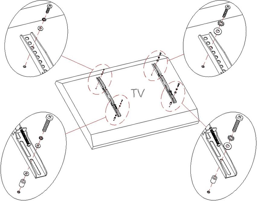
MAXIMUM RECOMMENDED WEIGHT LOADS

MANUFACTURER: Whalen Furniture Manufacturing
CATALOG: Belmont 3-in-1 TV Stand
MODEL # BJXLZEC44-GB
MADE IN VIETNAM

                                          FITS UP TO MOST 54” / 137.1 cm DIAGONAL FLAT PANEL TVs
                                          MAXIMUM LOAD 61.2 kg / 135 lb.

                                           FITS UP TO MOST 54” / 137.1 cm DIAGONAL FLAT PANEL TVs
                                           WITHOUT SWIVELING BRACKET
                                           MAXIMUM LOAD 61.2 kg / 135 lb.

                                          MAXIMUM LOAD 22.7 kg / 50 lb.

                  THIS UNIT IS NOT INTENDED FOR USE WITH CRT TVS. USE ONLY WITH FLAT
  PANEL TVS AND AUDIO/VIDEO EQUIPMENT MEETING RECOMMENDED SIZE AND WEIGHT
  LIMITS. NEVER USE WITH LARGER/HEAVIER THAN RECOMMENDED FLAT PANEL TVS OR
  EQUIPMENT. TO AVOID INSTABILITY, PLACE FLAT PANEL TV IN THE CENTER OF THE UNIT; THE
  BASE OF THE TELEVISION MUST BE ABLE TO REST ON THE SUPPORTING SURFACE OF THE
  UNIT WITHOUT OVER-HANGING THE EDGES. IMPROPERLY POSITIONED FLAT PANEL TVS, OR
  FLAT PANEL TVS INCLUDING OTHER EQUIPMENT THAT EXCEED RECOMMENDED SIZE AND
  WEIGHT LIMITS COULD FALL OFF OR BREAK THE UNIT, CAUSING POSSIBLE SERIOUS INJURY.
  FOR USE WITH TELEVISIONS WEIGHING 135 LBS (61.2 KG) OR LESS. USE WITH HEAVIER
  TELEVISIONS MAY RESULT IN INSTABILITY CAUSING TIP OVER RESULTING IN DEATH OR
  SERIOUS INJURY.

                GENERAL INFORMATION, TIPS and TRICKS
   1.   Please read the Assembly Instructions prior to assembling this product.
   2.   Remove all hardware from the box and sort by size.
   3.   Check to see that all hardware and parts are present BEFORE assembling.
   4.   Ask a friend to assist you with the assembly of this furniture.
   5.   To avoid damage, assemble the product on a sturdy, level and protective surface.
   6.   Please wait until all steps are completed before fully tightening bolts.
   7.   Make sure all bolts are tightly fastened before the unit is used.
This product is sold with one set of Tipping Restraint Hardware Kit. You must install the Tipping Restraint
Hardware between the wall and the TV console to prevent any accidents or damages. When properly installed,
this restraint can provide protection against the unexpected tipping of the unit due to small tremors, bumps or
climbing. The restraint is only a deterrent and is not a substitute for proper adult supervision. Use of tip-over
restraints may only reduce, but not eliminate, the risk of tip-over.

                                                        2
Parts and Hardware List
Please read completely through the instructions and verify that all listed parts and hardware are present
before beginning assembly.
A- Top Shelf Frame (Qty. 1) B- Middle Shelf Frame (Qty. 1)
C- Bottom Shelf Frame (Qty. 1) D- Lower Spine (Qty. 1) E- Upper Spine (Qty. 1)
F- Left Leg (Qty. 1) G- Right Leg (Qty. 1) H- Top Glass (Qty. 1)
I- Middle Glass Shelf (Qty. 1) J- Bottom Glass Shelf (Qty. 1)
K- Top Shelf Support (Qty. 2) L- Swiveling Bracket (Qty. 1)
M- Mounting Frame (Qty. 1) N- Monitor Bracket (Qty. 2) O- Cable Wheel (Qty. 2)
3Parts and Hardware List
(1) Suction Cup (2) 1/2” Bolt (3) 3/4” Bolt (4) 7/8” Bolt
(Qty. 18+1 extra) (Qty. 6+1 extra) (Qty. 20+1 extra) (Qty. 8+1 extra)
(5) Lock Washer (6) Flat Washer (7) 3-1/8” Bolt (8) Flange Nut
(Qty. 23+1 extra) (Qty. 23+1 extra) (Qty.1) (Qty.1)
(9) 1-1/8” Flat Head Bolt (10) Concrete Anchor (11) 2-1/2” Lag Bolt
(Qty. 2+1 extra) (Qty. 4) (Qty. 4)
(12) Lag Bolt Washer (13) Spine End Cap Hex Wrench Tipping Restraint Hardware Kit (Qty. 1)
(Qty. 4+1 extra) (Qty. 1) (Qty. 2) (Inside Plastic Bag)
TV Mounting Kit
AAA- M4 x 12 Bolt BBB- M4 x 30 Bolt CCC- M5 x 12 Bolt DDD- M5 x 30 Bolt
(Qty. 4) (Qty. 4) (Qty. 4) (Qty. 4)
EEE- M6 x 12 Bolt FFF- M6 x 35 Bolt GGG- M8 x 16 Bolt HHH- M8 x 40 Bolt
(Qty. 4) (Qty. 4) (Qty. 4) (Qty. 4)
III- M4 Lock Washer JJJ- M5 Lock Washer KKK- M6 Lock Washer LLL- M8 Lock Washer
(Qty. 4) (Qty. 4) (Qty. 4) (Qty. 4)
MMM- Large Spacer NNN- Small Spacer OOO- M4/M5 Flat Washer PPP- M6/M8 Flat Washer
(Qty. 4) (Qty. 4) (Qty. 8) (Qty. 4)
Tools required: Hex wrench (provided) and Phillips screwdriver (not provided).
4Assembly Instructions
B 4
C
B
D
4
4
C
UP
D D
④x4
NOTE: Please do not fully tighten all bolts until you finish assembling all parts. Once assembled, go back
and fully tighten all bolts. This will make the assembly easier.
1. Unpack the unit and confirm that you have all the hardware and required parts.
2. Locate the Lower Spine (D) and set back face down on a scratch free surface.
3. Align and attach 2 Shelf Frames (B and C) to the Lower Spine (D) with four 7/8” Bolts (4). Make sure
that the inside corner plates on the shelf frames will face up when the unit is turned upright.
NOTE: The Middle Shelf Frame (B) is adjustable. Choose the upper hole sets to increase the bottom
space.
5Assembly Instructions
F
B
C
G
F/G
B/C 4
④x4
4. Align and attach the Left Leg (F) to the Lower Shelf Frames (B and C) by inserting two 7/8” Bolts (4)
from inside the Shelf Frames through the pre-drilled holes on side rail and screw into the threaded
sockets on the Leg. DO NOT tighten the bolts.
5. Repeat the previous step with the Right Leg (G).
6Assembly Instructions
A
6
F/G 5
3 A
F
D
G
③x4 ⑤x4 ⑥x4
6. Stand the unit upright.
7. Align and attach the Top Shelf Frame (A) to the Legs (F and G) with the inside corner plates facing up,
using four 3/4” Bolts (3) with the Washers (5 and 6) through the end bracket holes of the Legs (F and G)
and screw into the back sockets of Top Shelf Frame.
7Assembly Instructions
2
A 5
6
K
A
F
K K
K
G 9
F/G
②x2 ⑤x2 ⑥x2 ⑨x2
8. Align and attach one Top Shelf Support (K) to the “L” bracket of the Top Shelf Frame (A) using one
1/2” Bolt (2) with the Washers (5 and 6). Secure the Top Shelf Support (K) to the Left Leg (F) with the
provided 1-1/8” Flat Head Bolt (9).
9. Repeat the same procedure to attach the other Top Shelf Support (K) at the other end.
10. Go back and tighten all bolts with the provided 4 mm hex wrench
If you choose Table-top Console
configuration, continue to the next step.
If mounting TV with the Floating Swivel
Mount, skip ahead to PAGE 13.
8Assembly Instructions for Table-top Console
7
D 65
8
13
D
D
⑦
⑤x1 ⑥x1 ⑧
11. Plug the Spine End Cap (13) all the way into the top of the Lower Spine (D).
12. Secure the Top Shelf Frame (A) to the Lower Spine (D) by inserting one 3-1/8” Bolt (7) with the
Washers (5 and 6) through the bracket hole and securely screw into the Flange Nut (8).
9Assembly Instructions for Table-top Console
O
O
D
3
O D
③x4
13. Attach 2 Cable Wheels (O) to the backside of the Lower Spine (D) with the 3/4” Bolts (3). Tighten the
bolts with the provided hex wrench.
14. The Cable Wheels (O) enable you to shorten, separate and route cables and cords. Using the Cable
Wheels, you can create a system for routing cables through channels, between components and to
power sources without tangled mess or annoying signal interference.
10Assembly Instructions for Table-top Console
H H/I/J
1
A
B
A/B/C
G
C
F
I
J
① x 18
15. Put the Suction Cups (1) firmly into top holes and metal tabs on 3 Shelf Frames (A, B and C), as shown.
TIP: If a Suction Cup resists insertion, try pressing down on the middle of the cup with the hex wrench
while twisting it clockwise into the hole.
16. Place the Top Glass (H) and Glass Shelves (I and J) in place beginning with the Bottom Glass Shelf (J).
Make sure that the glass shelf is properly centered. Push each glass shelf all the way back against the
Spine. Also, be sure to press down evenly and firmly each glass shelf onto the Suction Cups to make
sure they securely rest onto the Suction Cups.
NOTE: If a glass shelf is scratched, you can minimize the damage by using a BLACK marker and
filling in scratched area from underneath.
11Assembly Instructions for Table-top Console
TV
G
F
F/G
Tools required: Hex wrench (provided), Phillips screwdriver, stud finder, measure tape, pencil, power drill,
and 1/8” drill Bit (not provided).
17. Position the assembled console at the desired location against a wall. In case of uneven floor, Floor
Levelers are provided at the bottom of both Legs (F and G). Simply tilt the unit back and raise or lower
Floor Leveler by hand to correct tilting, as shown above.
NOTE: YOU MUST USE THIS TIPPING RESTRAINT TO ATTACH THIS UNIT TO THE WALL,
TO PREVENT THE UNIT FROM TIPPING, CAUSING ACCIDENTS AND/OR INJURIES.
18. Now, follow the instructions printed on the plastic bag containing the Tipping Restraint Hardware to
attach the tip-over restraint to the Spine and the wall.
19. The console is now ready for use. Be sure to position your Flat Panel TV in the center of the console.
NOTE: If you choose the Wall Mount configuration, proceed to PAGE 21.
12Assembly Instructions for
Floating Swivel Mount
E
E
D
A
A
E
D
653
6
D
35
6
5
3
③x6 ⑤x6 ⑥x6
20. Insert the Upper Spine (E) into the Lower Spine (D) and fasten it into place by using six 3/4” Bolts (3)
with the Washers (5 and 6).
13Assembly Instructions for Floating Swivel Mount
L
L
E UP
E
6
53
L
UP
E
6
35
③x6 ⑤x6 ⑥x6
21. Fasten the Swiveling Bracket (L) to the top of the Upper Spine (E) with six 3/4” Bolts (3) and the
Washers (5 and 6). Turn the Swiveling Bracket against the Upper Spine (E) when tightening the bolts
with the enclosed hex wrench. Make sure that the pivoting bolt head faces up.
NOTE: The Spine can provide two height options for the TV set. Refer to your TV size and adjust the
Swiveling Bracket to the desired height for optimum viewing.
14Assembly Instructions for Floating Swivel Mount
M
M L
L
BACK
E
6
5
2
6
52
6
5
D
2
②x4 ⑤x4 ⑥x4
22. Hold and attach the flat side of the Mounting Frame (M) onto the Swiveling Bracket (L) using four 1/2”
Bolts (2) and four Washers (5 and 6). Make sure that the recess holes on the Mounting Frame are
located at the bottom.
15Mounting Monitor Brackets to a Television with a Flat Back
TV
NOTE: For televisions with a curved or recessed back, proceed directly to next page.
23. Determine the correct diameter of the bolt the TV requires by hand threading them into the threaded
insert on the back of the TV. If you encounter any resistance, stop immediately. If you are unable to
find the correct bolt, consult a local hardware store.
24. Follow the appropriate diagram above to attach the Monitor Brackets (N) to the back of the TV with
selected fasteners. Make sure the Monitor Brackets are centered and level with each other. Secure the
bolts with a Phillips Screwdriver. DO NOT over tighten the bolts.
NOTE: Lean the TV up against a wall or other solid surface when attaching the Monitor Brackets. DO
NOT place the TV face down on the glass as this may cause permanent damage.
NOTE: If mounting your TV in the Wall Mount configuration, once you have completed the installation
of the monitor brackets, proceed to PAGE 21
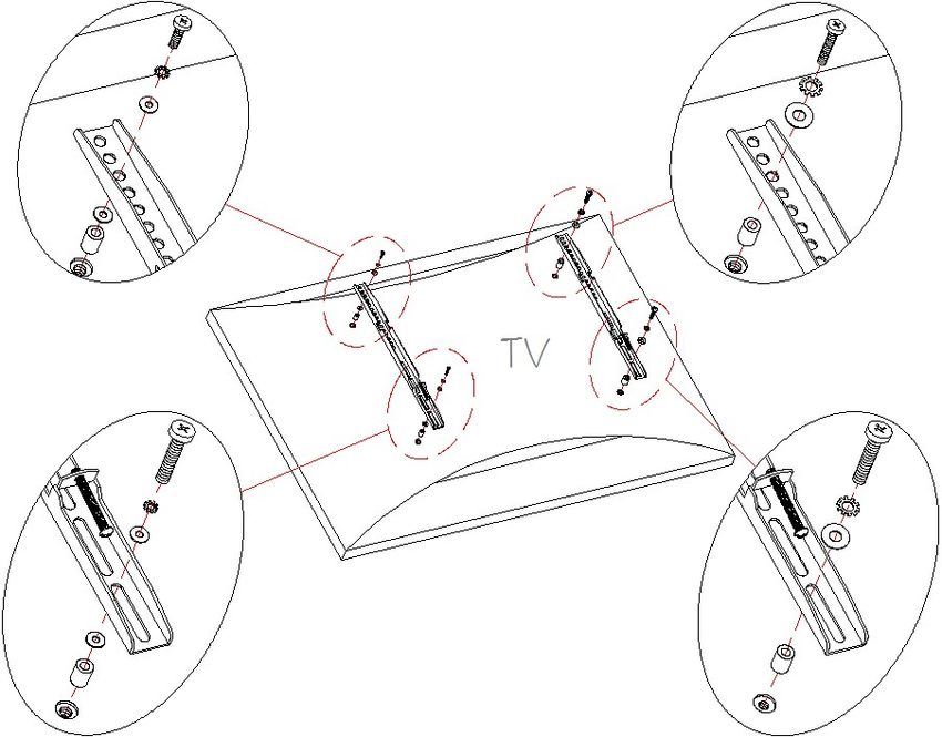
16Mounting Monitor Brackets to a Television with a Curved/Recess Back
TV
25. Determine the correct diameter of the bolt the TV requires by hand threading them into the threaded
insert on the back of the TV. If you encounter any resistance, stop immediately. If you are unable to
find the correct bolt consult a local hardware store.
26. Follow the appropriate diagram above to attach the Monitor Brackets (N) to the back of the TV with
selected fasteners. Make sure the Monitor Brackets are vertically centered and level with each other.
Secure the bolts with a Phillips Screwdriver. DO NOT over tighten the bolts.
NOTE: Lean the TV up against a wall or other solid surface when attaching the Monitor Brackets. DO
NOT place the TV face down on the glass as this may cause permanent damage.
NOTE: If mounting your TV in the Wall Mount configuration, once you have completed the
installation of the monitor brackets, proceed to PAGE 21
17Assembly Instructions for Floating Swivel Mount
1
N
M
N
N
2
M
M
N
MAKE SURE ALL BOLTS ARE TIGHT AND THE SPINE IS AT A 90 DEGREE ANGLE
AND USE A QUALITY LEVEL TO VERIFY THE MOUNTING FRAME IS LEVEL PRIOR
TO INSTALLATION OF TV.
27. Once the Monitor Brackets (N) are attached onto the back of television, ask for assistance to lift the
television up to hang the Monitor Brackets (N) onto the Mounting Frame (M). Set the hooks on the
Monitor Brackets over the Mounting Frame and then lower them onto the bars of the Mounting Frame.
NOTE: Loosen the Lock Bolt that is pre-attached to the Monitor Brackets to ensure an easy fit at the
bottom hooks.
28. Center the television and tighten both Lock Bolts with a long Phillips screwdriver until they hit the
underside of the Mounting Frame (M) to ensure your TV is safe and secure.
18Assembly Instructions for Floating Swivel Mount
O
E O
D
3
O D
29. Copy step 13 to attach the Cable Wheels (O) to the backside of the spine assembly.
TV
H H/I/J
1
A
B
A/B/C
G
C
F
I
J
30. Repeat steps 15 through 16 to install the Top Glass (H) and Glass Shelves (I and J) in place.
19Assembly Instructions for Floating Swivel Mount
TV
F/G
Tools required: Hex wrench (provided), Phillips screwdriver, stud finder, measure tape, pencil, power drill,
and 1/8” drill Bit (not provided).
31. Carefully move the console and position in your desired location against a wall. Now follow the
instructions printed on the plastic bag containing Tipping Restraint Hardware Kit to attach the tip-over
restraint to the Upper Spine (E) and the wall.
NOTE: You must install the Tipping Restraint Hardware with the unit in use to prevent any accidents
or damage to the unit.
32. The console is now ready for use. Swivel the TV left-or-right for optimum viewing control.
20The following steps are only for those who wish to mount their
TV directly to the wall. If you have already mounted your TV to
the Swinging Floater or plan to display your TV on the top
surface of the stand, disregard the following steps.
Assembly Instructions for Universal Wall Mount
Installing the Mounting Frame onto a WOODEN STUD WALL
407 mm
16 in / po
63.5 mm
2.5 in / po
4.8 mm / 0.2 in / po
166 mm
6.5 in / po
NOTE: If you are mounting your TV onto brick, solid concrete or concrete block, skip this section.
This assembly requires an electric drill, level and stud finder (not included).
33. Using a stud finder, locate the edges of the wood studs. Find the center line of each stud and draw a
vertical reference line on the wall over each one. Place the Mounting Frame (M) level against the wall
where you intend to mount the TV. Using the Mounting Frame (M) as a template, mark 4 drill points (2
on top, 2 on bottom) with a pencil on the vertical reference lines you just drew.
34. With an electric drill (not included) drill 3/16 inch (4.8 mm) diameter holes to at least 2½ inch (63.5
mm) deep on the four drill points. While holding the Bracket Plate in place, loosely screw in the Lag Bolts
(11).
35. Secure the Mounting Frame (M) to wall with the Lag Bolts (11) and the Washers (12) at the drill points.
Tighten the bolts firmly, but be careful not to over tighten.
Do not over tighten the Lag Bolts. Tighten Lag Bolts only until the Lag
Bolt Washer is pulled firmly against the metal plate of Mounting Frame. If there is a layer
of drywall or other material, this drywall or other material may not exceed 5/8 inch in
thickness. Failure to heed this caution may result property damage and/or personal injury.
21Assembly Instruction for installing the Mounting Frame onto a BRICK,
SOLID CONCRETE OR CONCRETE BLOCK WALL
407 mm
16 in / po
166 mm
6.5 in / po
63.5 mm
2.5 in / po
11 mm / 0.4 in / po
Maximum weight 61.2 kg /135 lb
Concrete Anchors should only be used for masonry mounting.
NEVER use the wall anchors to mount the unit to drywall.
NOTE: If you are mounting your TV to a wall with wooden studs, skip this section. This
assembly requires an electric drill and level (not included).
36. Begin by placing the Mounting Frame (M) level against the wall where you intend to mount the TV.
Using the Mounting Frame (M) as a template, mark 4 drill points with a pencil.
37. With an electric drill (not included) on its low setting, drill 7/16 inch (11 mm) diameter holes to at least
2½ inch (63.5 mm) deep. Insert the Concrete Anchors (10) into the pre-drilled holes so that they are
flush with the wall.
38. Place the Mounting Frame (M) level in the desired position against the wall. Secure the Mounting
Frame (M) to wall with the Lag Bolts (11) and the Washers (12) at the drill points. Tighten the bolts
firmly, but be careful not to over tighten.
22Assembly Instructions
1
N
M N
N
2
M
M
N
39. Attach the Monitor Brackets (N) to the back of the television following steps 23 and 24, or 25 and 26,
depending on the type of TV that you own.
40. Ask for assistance to lift the television up to attach the Monitor Brackets (N) onto the Mounting Frame
(M). Place the hooks of the Monitor Brackets (N) over the Mounting Frame (M) and then lower them
onto the bars of the Mounting Frame. Loosen the lock bolts that are pre-attached on the Monitor
Brackets to ensure an easy fit at the bottom hooks. Proceed to center the television. When the TV is in
its intended position, tighten both lock bolts with a long Phillips screwdriver until they hit the underside
of the Mounting Frame (M). This will ensure the TV is safely secured to the wall.
41. Place the assembled console under your TV. Finally, connect the A/V and power cables to your TV.
You are now ready to enjoy your wall-mounted Flat Panel TV.
23Care and Maintenance
For everyday cleaning, chrome, brass, aluminum, and painted metal surfaces can be kept looking their best
by wiping with a slightly damp, soft cotton cloth, or vacuum cleaner brush.
If soiled, wipe with clean sponge or cloth wrung out of water. Wipe dry with cloth or paper towel to avoid
water spots.
Do not use any harsh abrasives or chemicals to clean any metal surfaces as it may damage the protective
coating.
Metal will rust if the finish is scratched or if your furniture is exposed to excessive humidity, particularly in
salt water locations.
Most metal furniture has a protective coating to prevent rust, however rust may occur if the finish is marred
or wears away over time.
Stains or marks from crayons or ink markers will be difficult to remove.
In the event that your furniture is stained or otherwise damaged during use, we recommend that you call a
professional to repair your furniture.
Check bolts/screws periodically and tighten them if necessary.
Further Advice about Metal Furniture Care
It is best to keep your furniture in a climate-controlled environment. Continual exposure to damp and wet
environment can cause corrosion. It is advised to keep furniture away from direct sunlight as it may damage the
finish. Indoor furniture is not recommended for outdoor use.
Proper care and cleaning at home will extend the life of your purchase. Following these important and helpful
tips will enhance your furniture as it ages.
We hope you enjoy your purchase for many years.
Thank you for your purchase!
QUALITY GUARANTEE
We are confident that you will be delighted with your Whalen Furniture purchase.
Should this product be defective in workmanship or materials or fail under normal use, we will repair or
replace it for up to one (1) year from date of purchase. Every Whalen Furniture product is designed to meet
your highest expectations. We guarantee that you will immediately see the value of our fine furniture.
This warranty gives you specific legal rights and you may also have other rights which vary from state to
state or province to province.
Whalen Furniture Manufacturing,
1578 Air Wing Road
San Diego CA, 92154 USA
Customer Service: 1-866-942-5362
8:30 a.m. - 4:30 p.m., PST, Monday to Friday
www.whalenfurniture.com
24You can also read