Product Visualization Workflow from Inventor to 3ds Max to the Client
←
→
Page content transcription
If your browser does not render page correctly, please read the page content below
MFG469093
Product Visualization Workflow from Inventor to 3ds
Max to the Client
Steven Schain
Post-Production Supervisor / M & E Content Manager
4D Technologies

 Learning Objectives
     •   Discover the connection between SketchBook, Inventor, and 3ds Max for an optimal
         design workflow.
     •   Learn how to import an Inventor model into 3ds Max 2021 for use with the Arnold
         renderer.
     •   Learn how to create and configure scene materials and lighting.
     •   Learn how to place cameras and create simple fly-through animations of the final design.

Description
In the real world, one program just can’t do it all. Sketching, massing models, final design,
animation, and rendering of engineering models; this class will discuss the workflow for using
multiple Autodesk products in a production environment. Discover the ins and outs of this
workflow, starting with a SketchBook, moving to a massing model, then Inventor software for
final design, and finally 3ds Max software and Arnold software to render the final animation.
Learn how Drive can help manage the workflow files, review the Inventor-to-3ds Max import
process, and learn how to render photo-quality images. Use Physical Materials and the Sun
Positioner to simulate outdoor lighting and composition to create compelling images. Utilize the
Physical Camera controls to adjust the scene exposure and depth of field. Get ahead of the
competition by learning to create your renderings using photographic composition in a
streamlined workflow.

Speaker
Steven Schain, post-production supervisor and content development manager of Media &
Entertainment and Design products for CADLearning products from 4D Technologies. Content
development includes 3ds Max, Maya, Inventor and Fusion 360. In 1998, Autodesk recognized
Steven as one of only 16 Autodesk Training specialists worldwide. He has since contributed to
Autodesk's certified courseware for 9 releases of 3ds Max, was a co-developer of Autodesk's
ACI Program and 3ds Max’s fundamental standards, and is currently an Autodesk Certified
Instructor. As a premier Autodesk trainer, he has continued teaching end users, companies, and
many others, including The Walt Disney Company, Guess, and the United States Army. As a 9-
year veteran of Autodesk University and a featured speaker, Steven has taught classes ranging
from creating particle fountains in 3ds Max, to classes on 3D printing and entrepreneurship.
sschain@cadlearning.com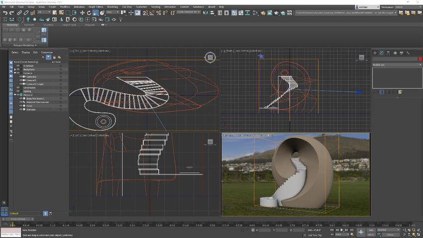
Table of Contents
Introduction ................................................................................................................................ 1
The Project ................................................................................................................................ 2
   Autodesk Sketchbook Mobile ................................................................................................. 2
   Designing the Memorial .......................................................................................................... 3
   Setting the Project Directory ................................................................................................... 3
   Loading a Default Scene ........................................................................................................ 4
   Layers .................................................................................................................................... 5
   Importing the Assembly .......................................................................................................... 6
   Import Settings ....................................................................................................................... 6
      Importing the Inventor Assembly ......................................................................................... 7
   Repositioning and Scaling the Assembly ...............................................................................11
Working with the Camera ..........................................................................................................12
   Creating the Keyframes .........................................................................................................12
Working with Materials ..............................................................................................................14
      Converting the Scene ........................................................................................................14
      Editing Material Properties .................................................................................................14
Rendering with Arnold ...............................................................................................................15
      Configuring Arnold .............................................................................................................16
      Output Size and File Type ..................................................................................................17

                                                                                                                                     Page 1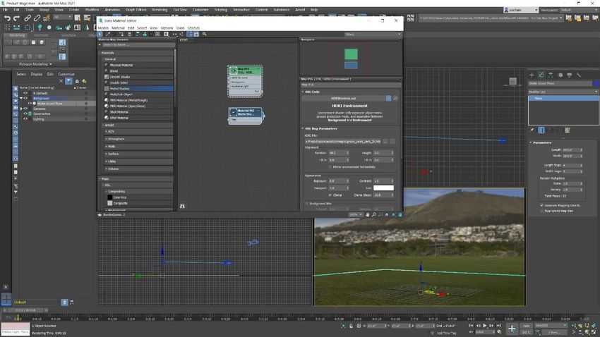
Introduction
As a designer or engineer, you can use Autodesk’s Inventor software to create buildable
designs for anything from simple parts and sculpture all the way to highly complex mechanical
assemblies. There are many times when it is helpful to see a design rendered with high quality
materials in an environment similar to where it will be placed.

Visualization using an animated camera is a tool for showing off a design in a way that still
pictures and diagrams cannot convey. 3ds Max is the ideal environment for rendering of
Inventor designs. You can import your Inventor design directly into 3ds Max. Once imported,
you can place it in a premade environment, apply materials, and render an animation.

Presenting a compelling animation involves being able to coordinate the animation of multiple
objects within the same scene. Once the animation is complete, you need to decide what the
output will be for the animated sequence.

An animated sequence can be rendered directly to a video file that can be played back at full
speed. However, it’s often better to render out to a sequence of files that can be turned into a
video file later.

The level of quality of final rendering will usually be based on certain requirements. If you’re
running a test to see if the animation looks the way you want it to, you can save a preview
rendering of the viewport. When it comes time to create your final rendering, Arnold can create
a high-quality realistic rendered animation.

This class will discuss and outline the steps you would take to go from an Autodesk Inventor
design file to a fully rendered animated sequence using 3ds Max 2021 and Arnold.

                                                                                            Page 1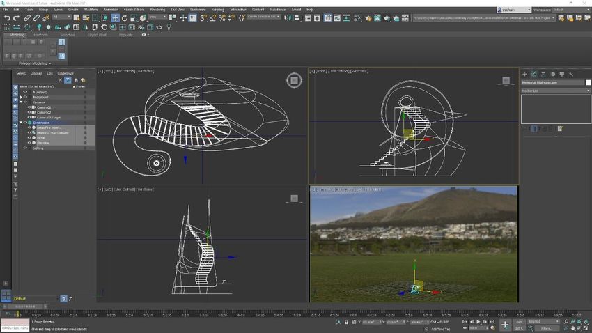
The Project
This project is a sculpture design I created for a memorial to suicide awareness. While I’d like to
say the initial idea is original, it’s based off of an urn design that I had seen previously. When I
saw it, I took a few minutes and pulled out my phone to make a sketch of the design.

Autodesk Sketchbook Mobile
Autodesk has some amazing tools in its vast toolbox, and one of them is Autodesk Sketchbook.
Sketchbook is been around for a very long time and is available as a mobile app that can be
used on a smartphone. My phone is a Samsung Galaxy Note 9 and has a built-in pen that I can
use to sketch on the screen. Using my limited sketch abilities, I sketched a rough idea of the
design and was able to build the rest of it from memory.

        MY ATTEMPT AT SKETCHING THE MEMORIAL DESIGN IN AUTODESK SKETCHBOOK ON MY PHONE.

                                                                                             Page 2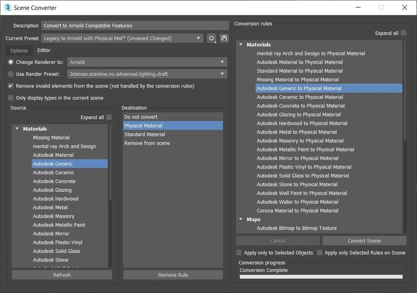
Designing the Memorial
My plan is to create the design in Autodesk Inventor. The structure will incorporate a full-size
staircase made from concrete winding its way up into a copper sculptural element with a portal
at the top. At the base of the staircase is an eternal flame. The model that’s in the Autodesk
Inventor file is a scale model of the full-size sculpture that is 12 inches tall and can be 3D
printed. So, when I do the visualization, I can easily scale it up so that it is life-size, which would
be 12 feet tall.

                     THE MEMORIAL SCULPTURE AS DESIGNED IN AUTODESK INVENTOR.

Once the design is complete in Inventor, it’s time to switch over to 3ds Max. Here, I’ll set up a
project folder and start developing the visualization for the memorial.

Setting the Project Directory
Before doing anything in 3ds Max, it’s important to configure a project path. There is a default
project directory setup that I’m going to use for this animation. (If you don’t work with project
directories, I highly recommend using them, as it’s a very good way to organize individual
projects.)

           1. In the application menu, choose Project > Set Active Project.
           2. Navigate to the MFG469093 - Viz 3ds Max Project directory and select the
              folder as the current project directory.

Now, when you load and save files, you can save them to the scenes directory within that
project folder.

                                                                                                Page 3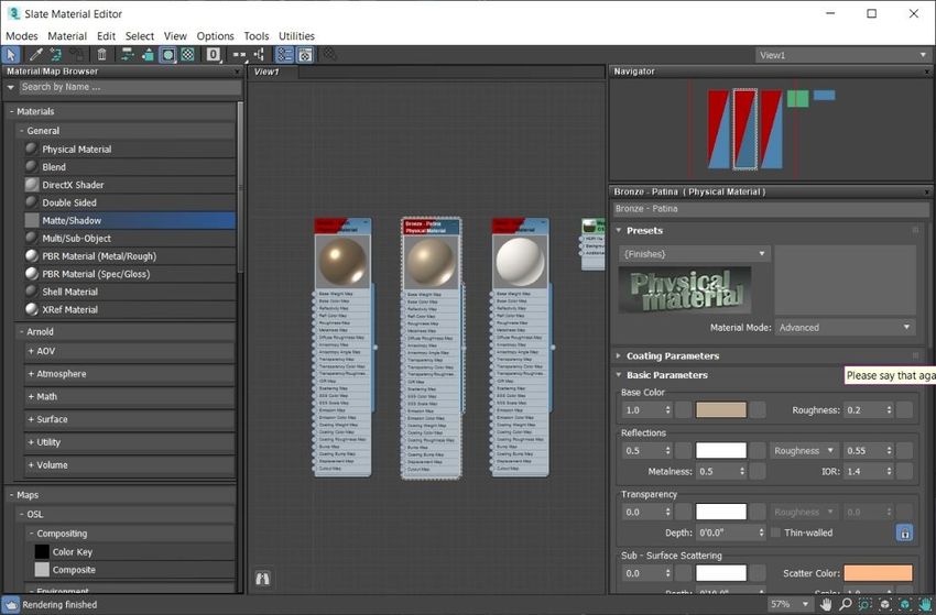
Loading a Default Scene
Starting with a scene that has lighting and a background already in it saves time when
visualizing a design. Furthermore, it is good practice to have several pre-built environments that
you can use for rendering product designs. These environments are pre-lit and pre-textured,
making it easier to focus on the product you are animating and rendering.

Using preconfigured environments is optional, but if your goal is to render a high-quality
animation of an Inventor assembly, it's helpful to use a pre-built file that has many of the
settings already configured. That’s not to say you won’t have to make any changes, but it gives
you a good starting point.

     YOU CAN HAVE SEVERAL PRE-BUILT ENVIRONMENTS THAT YOU USE FOR RENDERING DESIGNS. THESE
            ENVIRONMENTS ARE HELPFUL BECAUSE THEY CAN BE PRE-LIT AND PRE-TEXTURED.

                                                                                           Page 4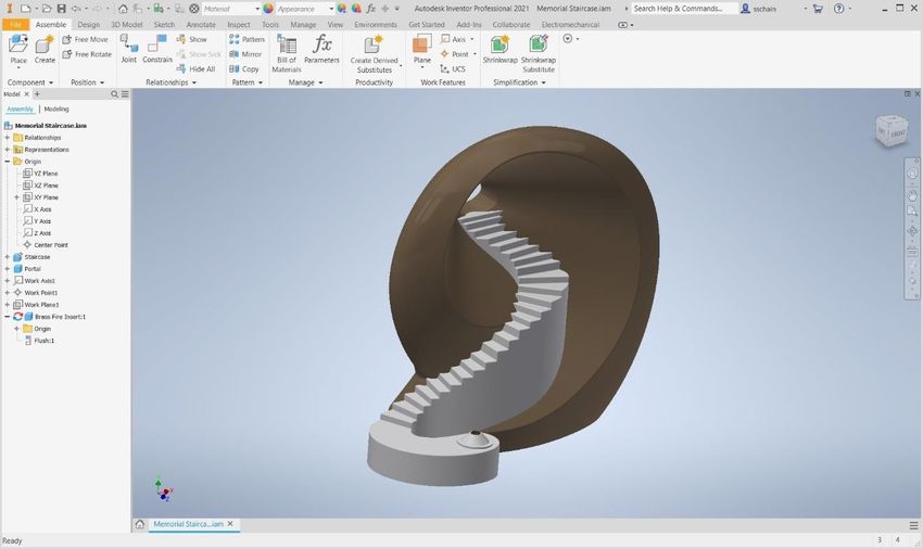
Layers
Another reason to start with a preconfigured scene is because you can have some layers preset
that help to isolate the lighting and cameras, as well as the background and construction
objects.

Looking at the Layers dialog for this project’s starting file, you’ll see that I have a Background
layer, a Cameras layer and a Lighting layer. Also notice that those three layers are frozen,
which means that I cannot pick them in the viewport.

                   THE SCENE EXPLORER CONFIGURED TO SHOW THE AVAILABLE LAYERS.

The advantage to working with frozen layers is that you don’t have to worry about accidentally
selecting the lights or moving cameras. And notice there is also a construction layer that’s the
current layer, so anything you build will be created on that layer. If I want to animate one of the
cameras that are in the scene, I can unfreeze the layer and animate it.

                                                                                              Page 5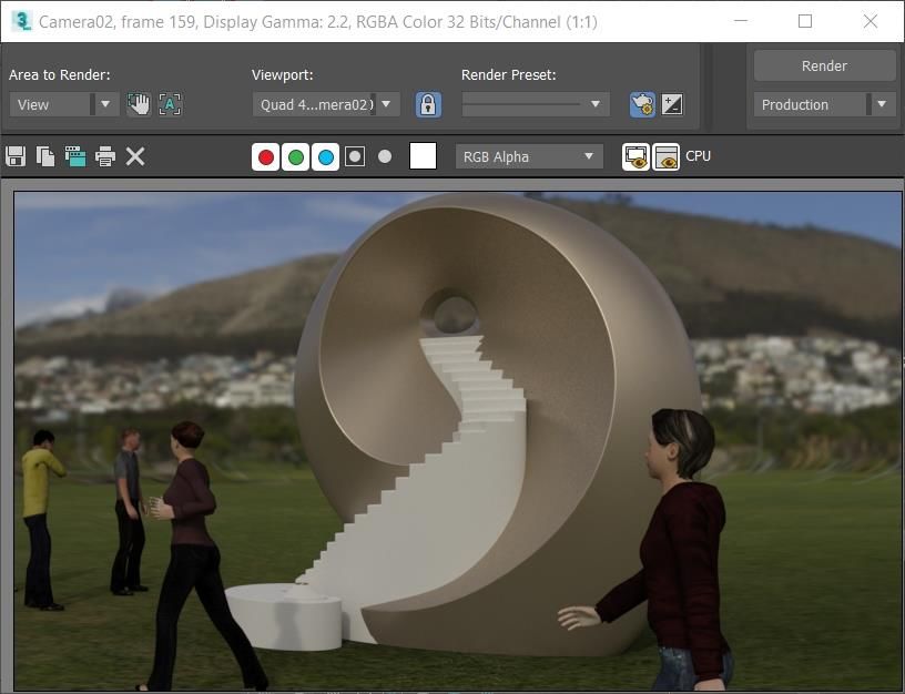
Importing the Assembly
3s Max allows you to import Autodesk Inventor files, whether they are parts (IPT) or assemblies
(IAM). These objects still keep the naming they have been given in Autodesk Inventor and are
imported as one of two types of objects: a Body Object, or an editable mesh. Once the file(s)
have been imported, they can be edited, just like any other model in 3ds Max.

                          THE AUTODESK INVENTOR FILE IMPORT DIALOG BOX.

Import Settings
The first thing to choose when importing is to decide whether you’re going to work with Body
Objects or Meshes in 3ds Max. These objects work in completely different ways.

A body object is an ACIS solid model that maintains the solid features from Autodesk Inventor.
Body objects are unique in that the render resolution and the viewport resolution can be
adjusted to fit your needs. It is completely possible to use a body object for both a very high-
resolution, rendered animation, and low-resolution, real-time simulation geometry.

A mesh object is a polygon mesh surface that’s generated from the imported data. The quality
of the mesh is determined by the mesh resolution option towards the bottom of the dialog. Once

                                                                                          Page 6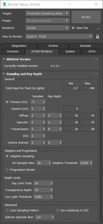
you import an Inventor file as a mesh, you don’t have the ability to change the resolution of the
geometry.

After that come the Assembly options. These three possible selections allow you to reference
duplicate parts, create layers based on the material, and add an object name to the material.
When the Create Layers By Material option is enabled, layer names are generated by
material, and all objects with that particular material are placed on that layer. This can be helpful
for organizing your scene.

Depending on how you want to organize your scene will depend on whether or not you enable
Add Object Name to Material. This option will use the imported material name in the name of
the object. Be aware that when importing Autodesk Inventor files, some of the object names
may be very long. While most will be based on the object name, keep in mind that some of the
standard hardware can have very long names. But overall, naming shouldn’t be too much of an
issue, as long as your Inventor file is logically named.

The Merge and Replace option is, simply put, whether you want to merge the objects together
in the current scene or replace the scene with the imported file.

The Material Options allow you to import the materials straight from Inventor; this does,
however, come with its issues, as not all Inventor materials have a direct correlation to materials
in 3ds Max.

The last options are whether you want higher or lower mesh resolution (if you imported Inventor
files as Mesh objects), and a choice of the vertical direction to be on the X, Y, or Z axes
(typically left on the Z axis).

Importing the Inventor Assembly

           1. From the File menu, click Import > Import.
           2. Open the Memorial Staircase directory.
           3. You can see both part files and assembly files in this directory.

       I’ve made it a little bit easier because I’ve moved everything into one directory.
       3ds Max will resolve links within an assembly file, as long as the directories for all of the
       parts are accessible and do not differ from the computer that this was designed on.

           4. Select the "Memorial Staircase.iam" assembly file, and then click Open.

                                                                                             Page 7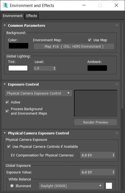
THE SELECT FILE TO IMPORT DIALOG BOX SHOWING THE MEMORIAL STAIRCASE ASSEMBLY AND PART FILES.

When you click Open, you’re presented with the import dialog box:

5. Select Import As: Meshes.

       There’s a little bit more computer overhead required when you use body objects
       because they are ACIS solid geometry, and the polygons have to be calculated for the
       surface. This is a primary reason meshes are used, as opposed to body objects. The
       mesh object is lighter and doesn’t require the same amount of computer overhead.

                                                                                         Page 8
6. In the Assembly Options group box, keep Reference Duplicate Parts enabled
and uncheck Create Layers by Material to disable it.
When Create Layers by Material is checked, the importer will create the layer for each
material in the assembly. In this case, there are only three objects which will be added to
a new layer once they are imported, so there is no need for layers based on materials.
7. In the Merge/Replace Options group box, enable Merge with Current Scene.
8. In the Material Options group box, enable both the Import Inventor Materials
and Assign Material IDs options.
This will cause 3ds Max to use the materials assigned to each part inside of Inventor.
This makes it much easier to edit materials on each object, since it is already assigned.
9. Set the Mesh Resolution value to 3.
10. Lastly, set the Inventor File Vertical Direction to the Y Axis option.
By setting the vertical direction, you are indicating which direction is up in the Inventor
file. This will import the geometry with the orientation adjusted to compensate for the fact
that the Y axis is the Up axis in the current assembly file.
11. Click OK, and the import process will begin.
3ds Max will take some time to process the assembly and create the individual pieces of
geometry.
Once the import process is complete, the Memorial will be placed where it was built within
Autodesk Inventor. In this case, it will have to be moved to the center of the scene and scaled
so that it is 12 feet tall.
Note: One additional—and important—thing to understand is that you can build multiple
assembly files, and if you place them all relative to each other, they will import into 3ds Max in
the proper location.
Page 9THE MEMORIAL STAIRCASE ASSEMBLY SHOWN AS IT IS IMPORTED.
Once the assembly is imported, I can create a new layer, and assign the models to that new
layer.
THE MEMORIAL MODELS ASSIGNED TO A NEW LAYER.
Page 10Repositioning and Scaling the Assembly
The assembly was imported from Inventor; however, it is not positioned or scaled the way I
would like for the current scene. By adding an XForm modifier, I can position and scale the
model by assigning the modifier to the Memorial staircase.IAM assembly group object.
THE MEMORIAL ASSEMBLY POSITIONED AND SCALED WITHIN THE SCENE.
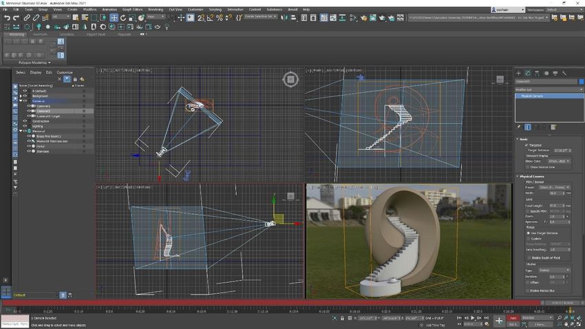
Page 11Working with the Camera
At this point, I’m going to set up a simple camera animation that takes the currently viewed
camera, which is camera02, and moves it from one side of the Memorial to the other.
When setting up the animation, the first thing to do is to set up your frame rate. For example, if
the animation is going to be for film, it will need to be set at 24 frames per second. However, if it
is for video, then it will need to be set at 30 frames per second. After that, the length of the
animation, as well as the start and end times, will be needed to be set.
I’m doing a simple fly-around of this Memorial, so I want to make sure I have enough time to see
it. Remember—this is going to be shown to a client, so you don’t want it to go by too quickly.
Will 10 seconds be enough time, or will I need to make the length 30 seconds? Determining this
ahead of time will avoid issues that can occur if you have to retime an animation later.
To animate a camera, I can either use keyframes or place the camera along a path, if I need a
more complex camera animation. Here, I’m simply going to move the camera from the right side
of the Memorial to the left side of the Memorial over a period of 30 seconds.
Creating the Keyframes
1. In the Top viewport, select camera02.
Before I start creating key frames; I’ll set the length of the animation.
2. Open the Time Configuration dialog.
3. In the Animation group box, set the Length to 30 seconds.
4. Click OK to close the dialog.
Once I’ve set the length of the animation, I’ll use the Auto Key option to animate the camera
from frame 0 to 30 seconds.
Page 125. Turn ON Auto Key.
6. Click the Key Filters option.
7. In the Set Key Filters dialog, enable only the Position option
(uncheck/disable Rotation, Scale, and IK Parameters).
I ONLY WANT TO BE CREATING POSITION KEYFRAMES.
8. Drag the Time Slider all the way to the right, or click Go To End in the playback
controls.
9. Use the Move tool to move the camera over to the left side of the Memorial
model in the top view. Then, move it up a little bit in the left view.
10. Scrub the Time Slider to see in the camera viewport what the animation is going
to look like.
THE MEMORIAL, AS VIEWED FROM THE LEFT SIDE AFTER 30 SECONDS.
11. Turn OFF Auto Key.
Page 13The idea here is not to create the final version of the animation; rather, it’s to rough it in. Later, I
can edit it using the Curve Editor and the Dope Sheet, if I so choose.
Working with Materials
Begin by selecting the materials from each object. There are only three objects in this scene
that need materials edited. There are already two materials in the view1 workspace: one is the
OSL shader for the HDRI Environment, and the other is a Matte/Shadow material applied to the
ground plane to catch shadows and transfer them to the background.
Converting the Scene
Before making changes to the materials, convert the imported Inventor materials using the
Scene Converter. When the Inventor materials come in, they are configured as Autodesk
Generic materials. However, they need to be converted to physical materials, which work with
the Arnold renderer and are easier to use than the Arnold standard material.
THE SCENE CONVERTER CONFIGURED TO CONVERT AUTODESK MATERIALS TO PHYSICAL MATERIALS.
Editing Material Properties
With the materials converted, I can begin editing the materials that are assigned to each object.
Here, I need to determine how detailed the materials need to be. While I want the Memorial to
look realistic, I have a very specific look that I’m aiming for. The portal section and the stairs will
be smooth materials. The portal section will be a copper-colored smooth surface, and the stairs
will be an off-white colored surface. There is also a brass insert that’s going into the eternal
flame spot at the bottom of the stairs that will be a shiny bronze color.
Page 14I can use the eyedropper in the Material Editor to pick the material from each object, then
arrange the materials horizontally within the view1 work area. With the materials organized, I
can edit each to look the way I want them to. These are all physical materials, and the editing
that I’m doing is going to be fairly minimal, compared to creating complex materials using
multiple texture maps and mapping coordinates.
THE SLATE MATERIAL EDITOR SHOWING THE THREE MATERIALS ASSIGNED TO THE PARTS OF THE MEMORIAL
ASSEMBLY.
Rendering with Arnold
Now that I’ve animated the camera and edited the materials, I’m ready to set up and render the
scene. When rendering a final sequence, there are certain things that are important keep in
mind.
The assembly should be in some kind of environment, but what that environment consists of is
entirely up to you. It could be as simple as creating a floor or a light box; or, you can build an
elaborate environment for your animated assembly to be in. For instance, if you’re showing the
animation of an automotive robot, you might build an assembly line, to show the robot in its true
environment.
When you set up your environment ,you need to configure the lighting. Lighting is critical! You
can do everything right, but if your lighting is not good, then your rendering will not be good. You
don’t have to be a lighting expert—you just need to have lighting that’s well balanced. You can
even use the scene set up the way I have it here, with an OSL HDRI Environment shader that
will provide easy, realistic lighting.
Since this is a simple visualization, I’m not worried about the composition. I want the client to be
able to see the Memorial and what it will look like from different angles, so I’m less concerned
about following strict compositional rules.
Page 15Next, the scene exposure must be set properly. If the exposure is not set correctly, you could
overexpose or under expose the scene. One of the added benefits of using a predefined stage
to import the assembly into is that the exposure can be preset to match the lighting in the scene.
The scene uses the Physical Camera Exposure Control, and the exposure value is set in the
camera’s Exposure rollout.
THE ENVIRONMENT AND EFFECTS DIALOG WITH THE EXPOSURE CONTROL SET TO PHYSICAL CAMERA EXPOSURE
CONTROL.
Configuring Arnold
Once everything is set properly, it’s time to configure the rendering parameters. Part of setting
up the rendering parameters is configuring Arnold. Thankfully, Arnold is an easy renderer to
configure. Depending on the level of output quality you need, you can adjust the Samples and
Ray Depth in the General group box. The higher the values, the higher the quality and the
longer it will take to render. I generally start out with low settings to make sure that everything is
going to work, then I increase settings based on the type of lighting in the scene.
For a scene like this where there are not many specular reflections or transparent objects, I’ll
adjust the Diffuse Samples and Ray Depth, along with the Camera Antialiasing. To help
speed things up a little bit, I also turn ON Adaptive Sampling. This uses a threshold value to
determine what parts of the scene get more sampling than others.
Page 16THE RENDER SETUP DIALOG WITH MY STARTING ARNOLD CONFIGURATION.
Output Size and File Type
Determining the size of the rendered image should be done ahead of time. This is because the
aspect ratio of the final rendered image will change what you see through the camera lens. So,
you want to set that up as soon as you can. For this scene, I’m using the HDTV formatted
Output Size and rendering to 800 x 450 image resolution. This will be a low-resolution first pass
to make sure everything looks good. If I like the way this renderers, then I’ll increase the output
size for a final render.
THE OUTPUT SIZE OPTIONS CONFIGURED FOR HDTV.
Page 17Then, you need to determine the frames to render. Are you going to render the entire sequence,
or are you just going to render a few frames? For this animation, I’ll render the entire active time
segment, rendering every frame. I can choose to render every other frame or even every fourth
or fifth frame, if I want to speed up rendering time.
THE OUTPUT TIME OPTIONS SET TO ACTIVE TIME SEGMENT, RENDERING EVERY FRAME.
Finally, what image format will you need to use? Are you going to convert the sequence directly
into an animation video file, or will the sequence be edited later? If the sequence is going to be
taken into a compositing program, like Autodesk Composite, what image components do you
need for compositing? Once you have determined the image format, you are ready to render the
animation. For this animation, I’ll use PNG files to maintain quality, and I’ll open the sequence in
3ds Max’s ram player to save it to an AVI file.
THE RENDER OUTPUT SETTINGS CONFIGURED TO RENDER A SEQUENCE OF PNG FILES.
Once I click Render, the animation will begin rendering, starting with the first frame in the
current frame range. The speed of the rendering depends entirely on the speed of the computer
and whether you are able to distribute the rendering of each frame.
Page 18Once the rendering is complete, you will have a sequence of PNG file that you can convert to an
AVI file or import into a video editing or compositing program for further work.
Page 19You can also read