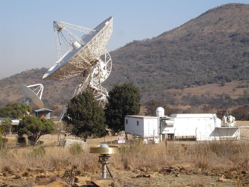
Introduction to DSTV dish observations - Aletha de Witt DARA-AVN May 2019 Observational & Technical Training HartRAO - AVN training site
←
→
Page content transcription
If your browser does not render page correctly, please read the page content below
Introduction to DSTV
                                               dish observations

                         Aletha de Witt
                    DARA-AVN May 2019
Observational & Technical Training HartRAO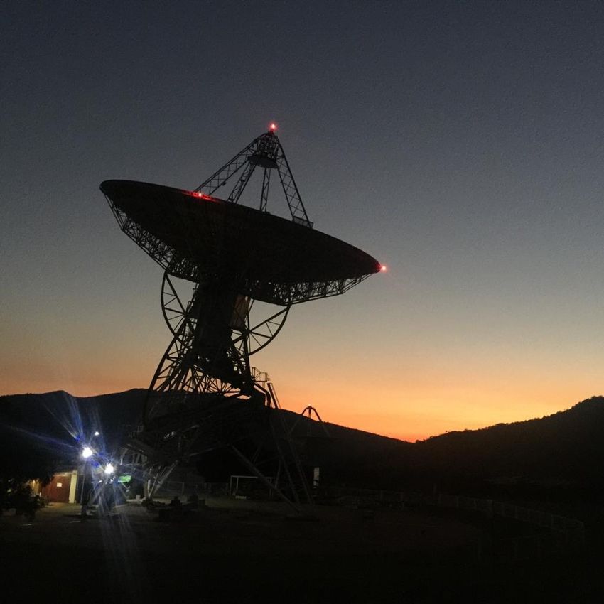
Theory: Radio Telescope Antennas

• A “classic” radio telescope for use in the microwave band has a circular
  parabolic reflector with a feed horn at the focus to collect the incoming
  microwaves and pass them to transistor amplifiers in the receiver.

• A DSTV satellite dish also works in this way. It can be used as a mini radio
  telescope by replacing the DSTV decoder with a radiometer for measuring the
  signal strength.
Theory: Radio Telescope Antennas

• Facts about the DSTV dish.

-   This is a 12 GHz radio telescope and is 50cm in diameter.

-   It can detect frequencies in the range of 11.7 to 12.2 GHz.

-   Satellite dishes have a smooth solid surface in order to reflect incoming waves with
    high efficiency

-   It is not a radio telescope system that can be used for serious sky surveys.

-   It can detect the Sun.

-   It can detect blackbody radiation such as 300 K trees, buildings, people, when
    viewed against blank sky.

-   It can be used to demonstrate the basic concepts of a radio telescope.

-   It can be used for student training and outreach .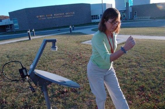
Theory: Radio Telescope Antennas
                                                                                     Block diagram of 12 GHz Satellite Antenna and Radiometer
                                                                                     Satellite dish - paraboloid with offset focus

                                                                                                                             Path of radio waves

                                                                                                                    Satellite dish receiver head =
                                                                                                                    Low-Noise Block converter (LNB)

                                                                                                         Microwave feed horn at focus of dish

                                                                                                         Radio frequency (RF) Low-Noise Amplifier (LNA)
                                                                                     Local               for 11700 - 12200 MHz
                                                                                     Oscillator

                                                                                                         Mixer
                                                                                     LO
                                                                                                         Intermediate frequency (IF) output
                                                                                     10700 MHz           IF = RF=LO

                                                                                          15V         Power for LNB
                                                                                                                        Radiometer components:

                                                                                                         Capacitor to block DC power to LNB
* Radiometer: measures the strength of the radio signal coming from the
         receiver on the dish. Build using spares from the 26m.                                          Attenuator
                                                                                                         for signal level adjustment

            * Supplies the 15V DC needed by amplifier on the dish.
                                                                                                         1000-1500 MHz amplifier
                     * Use a “square-law” detector =>                                                    Diode detector
                 output voltage proportional to input voltage.                                           Vout proportional Pin

          * Output voltage is displayed on a meter (arbitrary scale).                                    Low-pass filter

                                                                                                         Op-amp
            * Output voltage is fed to a loudspeaker (audio output).
* Hiss of varying levels of intensity => hiss is “white noise” radio equivalent of                        Loudspeaker                  Voltmeter
                         white light we see with our eyes.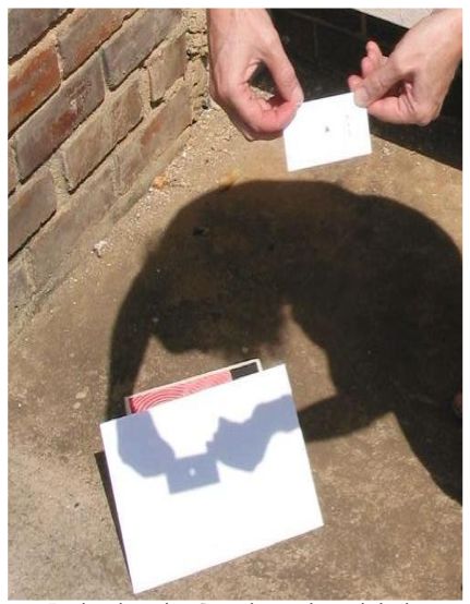
Theory: Radio Telescope Antennas

  circular aperture                diffraction pattern

     • plane wave arrive at a circular aperture
     • constructive & destructive interference
     • circular symmetric diffraction pattern
     • Central maximum & decreasing rings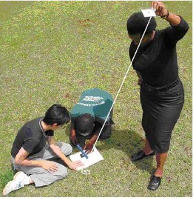
Theory: Radio Telescope Antennas
In the same way a reflector antenna responds to radiation from different angles
Theory: Radio Telescope Antennas

   The beam cross-section through the
                                               Beam cross-sections of ideal and a typical
  beam pattern of an ideal antenna and a
                                                real antennas, with a logarithmic vertical
practically realisable antenna, shown with a
                                                  scale to show the sidelobe structure.
linear vertical scale (unblocked aperture).
Theory: Radio Telescope Antennas

                                    “Ideal” antenna would produce a
                                    beam that captures 100% of the
                                   incoming energy in the main beam
                                       and have no sidelobes =>
                                      main beam efficiency = 1.0
                                       (usually between 0.6 - 0.8)

                                     DSTV dish => 0.75 based on
                                      measurements at HartRAO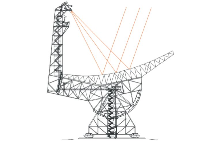
Theory: Radio Telescope Antennas
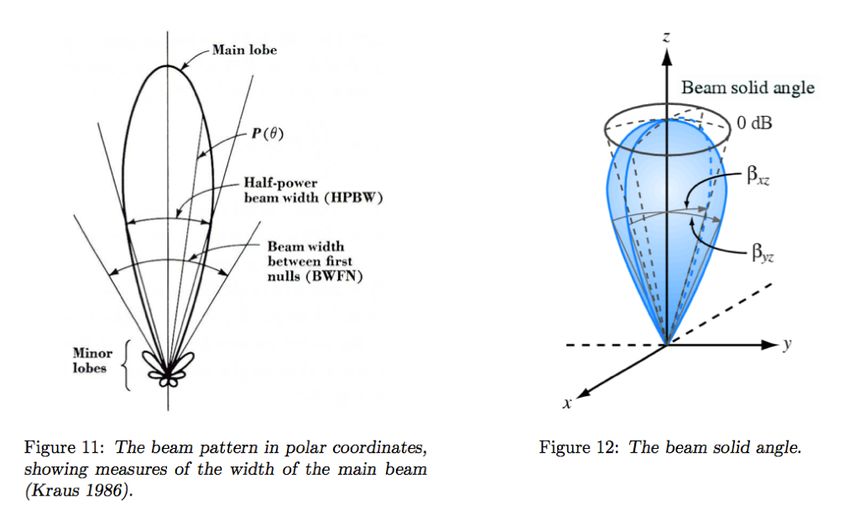
FWHM = ~ 1.2λ/D [radians] => the “beamwidth” of the antenna
—FWHM—
BWFN
BWFN => first min or null in pattern ~ 2.4λ/D [radians]
Theory: Angular Sizes
                           Beam pattern in polar coordinates,
                           showing measures of the width of the
                           main beam (telescope beam size)

                        F W HM = 1.2 /D [radians]

                           Outside of the main beam, the telescope
                           is still weakly sensitive to radiation coming
                           from other directions, in what are known as
                           its “sidelobes”

                           Man-made radio signals (RFI) become a
                           problem if they can be detected in these
                           sidelobes
Theory: Angular Sizes
A radio telescope looks at a sky which has
a continuous, varying, distribution of
radio emission
There are objects of large angular extent
and objects of small angular extent than
the main beam of the telescope
What the telescope “sees” is the actual
radio brightness distribution in the sky
convolved with (“smeared out” by) the
beam of the telescope. The bigger the
beam, the more it smears out.Theory: Angular Sizes
• Angular area is called a solid angle and the units are radians^2 or
steradians (sr)
⌦ = 2⇡(1 cos✓)
F W HM = 1.2 /D [radians] ⌦A = 1.133(F W HM )2 [sr]Theory: Angular Sizes
• For a spherical object whose actual diameter equals d and where D is the
distance to the centre of the sphere, the angular diameter can be found by
the formula: d
Angular diameter = arcsin( 2D )
• For very distant or stellar objects, the small angle approximation can be used:
d d
Angular diameter = D Angular radius = 2D
r2 > r1, θ1 = θ2 r4 > r3, θ4 < θ3
physical radius and angular radiusTheory: Angular Sizes
• Angular area is called a solid angle and the units are radians^2 or
steradians (sr)
⌦ = 2⇡(1 cos✓)
✓s = d/D [radians] for small ✓, ⌦s = ⇡✓2 [sr]Theory: Radio Telescope Antennas
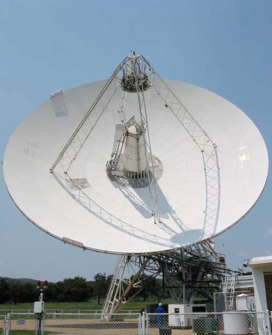
• A “classic” radio telescope for use in the microwave band has a circular
parabolic reflector with a feed horn at the focus to collect the incoming
microwaves and pass them to transistor amplifiers in the receiver
Offset parabolic dish antenna
Parabolic dish antennaTheory: Radio Telescope Antennas
Theory: Radio Telescope Antennas

  Factors reducing the aperture efficiency (0.80, 0.75, 0.64)
Theory: Radio Telescope Antennas
                                           Pointing accuracy
                             radiation cooling

                     wind

                                                      solar flux

              ambient temp
              change

                                gravity
                                 gravity

Pointing accuracy
Theory: TB and TA
Blackbody: hypothetical object
that is a “perfect” absorber and
a “perfect” emitter of radiation
over all wavelengths.
The spectral distribution of
the thermal energy radiated by a
blackbody depends only on its
temperature.
Brightness as a function of frequency.
Blackbody radiation from solid objects of the same angular size, at different temperatures.Theory: TB and TA
blackbody radiation curves
have quite a complex shape
(described by Planck’s Law)
Energy is theoretically emitted at
all wavelengths.
Intensity at all wavelengths
increases as the temperature
of the blackbody increases
As temperature of the blackbody
increases, the peak frequency
increases (Wien’s Law).
Total energy radiated (area under
curve) increases rapidly as the
temperature increases (Stefan–
Boltzmann Law).Theory: TB and TA
For a black body radiator, the
Brightness B is given by;
2h⌫ 3 1
B= c2 eh⌫/kT 1
2 1 1
[W m Hz sr ]
Rayleigh-Jeans Law:
The brightness B and hence the
power measured by a radio
telescope is proportional to the
temperature T of the emitting source
2kT
h⌫Theory: TB and TA
2kT
h⌫ effective temperature that
- Orion Nebula at 300 GHz ~ 10-100 K (“warm” thermal molecular clouds) a black body would need to have.
- Quasars at 5 GHz ~ 10^12 K (non-thermal synchrotron)Theory: TB and TA
• The “antenna temperature” TA of a source is the increase in in temperature
(receiver output) measured when the antenna is pointed at a radio emitting
source.
• NB: The antenna temperature has nothing to do with the physical
temperature of the antenna.
• The antenna temperature will be less than the brightness temperature if the
source does not fill the whole beam of the telescope. Must also correct for
the aperture efficiency.
TB = ⌦⌦As ✏TmA [K]
• By pointing the antenna at objects of known temperature that completely fill
the beam we can calibrate the output signal in units of absolute temperature
(Kelvins). One can think of a radio telescope as a remote-sensing thermometer.Theory: Detecting Radio Emission
• When the telescope looks at a radio source in the sky, the receiver output is
the sum of radio waves received from several different sources:
The sum of these parts is called the system temperature Sky temperature Tsky ~ 10 K
Tsys = TBcmb + TA + Tat + Twv + Tg + TR [K]
CMB radiation coming from every
direction in space. The amplifiers in the
~ 2.7 K at 1.4 or 4 GHz, antenna produce their own
reducing to 2.5 K at 12 GHz electronic noise, receiver
Radiation from the water vapour in
noise temperature.
the atmosphere.
At 12 GHz adds 1 - 2 K, depending
on the humidity.
The emission from the radio source
we want to measure, which
produces the antenna temperature.
The radiation the feed receives
through the antenna sidelobes from
Radiation from the dry atmosphere. the (warm ~ 290 K) ground.
Adds about 1 K. Adds 5 - 15 K pointing straight up at
zenith, and increases when pointing
close to the horizon.Experimental Procedure: • Turn the DSTV dish to blank sky. Listen to the speaker or look at the meter. • Now turn the DSTV dish towards the ground and see/hear the difference. REMEMBER The noise level depends on the temperature of the object. • Sky – shows lowest signal level. Note that when aimed at different parts of the sky the signal level hardly changes. This means that it is not sensitive enough to detect stars. • Remember that blank sky is about 10 K while the ground is about 300 K !
Experimental Procedure:

• Turn the DSTV dish towards the Sun.
Experimental Procedure:

• Projecting the Sun through a pinhole
Experimental Procedure:

• Calibrating the radio telescope:

• Why isn’t the Sun, with all its enormous energy (temperature of 6000 K),
  pinning the meter?

• It turns out that the DSTV dish has a beam width of 3.4° while the Sun appears
  to be only 0.5° in our sky. Thus the area of the dish occupied by the Sun is
  small and the signal appears weaker than the ground at 300K.

• FWHM (beamwidth) => ~ 1.2λ/D (λ = 12 GHz = 2.5 cm, D = 50 cm).
                                              ⌦A = 1.133(F W HM )2 [sr]
• Measuring the diameter of the Sun => θ = d/2D (diameter = 0.5°).

                                           ⌦s = ⇡✓2 [sr]
• We could fit ~66 Suns into the beam of the dish (ratio of the angular size
  of the beam to the angular size of the Sun).
Experimental Procedure: • Calibrating the radio telescope: • We need to establish a scale of Kelvins per radiometer output unit. We do this by using the sky at zenith as a “cold load” and the ground as a “hot load” • If V1 and V2 are the two meter readings on the sky and ground and c is a constant of proportionality (kelvins per meter reading); cV1 = TR + Tsky (TR + Tsky = Tsys => system temperature) cV2 = TR + Tground (TR => electronic noise generated by receivers) • Some typical values: V1 = 10, V2 = 30, Tsky = 10 K, Tground = 300 K • Tsky = TBCMB + Tat + Twv + Tg ~ 10 K • c = 14.5 kelvins per meter division, TR = 135 K
Experimental Procedure:

• Measuring the brightness temperature of the Sun

• If V3 is the meter reading for the Sun; cV3 = TR + Tsky + TA

• Some typical values: V1 = 10, V2 = 30, Tsky = 10 K, Tground = 300 K, TSun = 24

• c = 14.5 kelvins per meter division, TR = 135 K

• TA = 203 K                                           ⌦A T A
                                              TB =     ⌦ s ✏m    [K]
• TB = 203 K x 66 = 13400 K (only a fraction of beam filled by source)

• Correcting for the efficiency of the dish 13400/0.75 = 18000 K at 12 GHz

• How does your result compare to the temperature usually quoted for the Sun’s
  photosphere (light emitting surface) ?
Experimental Procedure:
Equations
Tsys = Tsky + TA + TR [K]
Tsky = TBcmb + Tat + Twv + T g ⇠ 15 K
TR + Tsky = cV 1 [K]
TR + Tground
1 radian
= cV 2 [K]
= 57.29577 degrees Equations
TR + Tsky + TAsun = cV 3 [K]
✓s = d
[rad] TB = suns/beam ⇥ TA [K]
2D
nr of suns/beam= ⌦beam
⌦s
s = ⇡✓s 2 [sr] ⌦A T A
TB = ⌦s m [K]
HPBW/FWHM ⇠ 1.22 ⇥ [rad]
1 = radians ⇥ 180
D
⇡
⌦A = 1.133(F W HM )2 [sr] 180 2
1sr = ( ⇡ ) square degrees
1 radian = 57.29577 degreesMore Fun Activities • Body temperature detection. • Nearly anything with a temperature can be detected with a radio telescope and people are no exception. Having a temperature of 300K (37°C), your reading will be similar to the ground if you fill the beam. • The first musical use of this radio created music was the Theremin, played by waving your hands near antennas to vary pitch and amplitude Look it up on the web, it’s fascinating! Léon Theremin
More Fun Activities

• Satellite detection.

• Many geo-stationary satellites are in orbit above the Earth and many transmit
  radio signals. Remember though that the sun is a broadband (extremely!)
  transmitter whereas the satellite is a very narrow beam transmitter.

• Most of these satellites orbit above the equator so figure out where your
  celestial equator is by taking you latitude and subtracting it from 90°. This
  is a rough altitude to look for satellites.
More Fun Activities

• Find the tree line and gaps between trees

• You could map the tree line using the angle of tilt of the antenna (altitude
  measured with an inexpensive angle finder available from hardware stores and
  the azimuth found with a compass).
More Fun Activities

• Measure the HPBW (FWHM) of the antenna.

• If the satellite dish is mounted on a tripod or mount so that it can be locked in
  position, then it is possible to carry out a “drift scan” across the Sun, as
  follows.

• Point the antenna to get the maximum signal from the Sun. Lock the antenna’s
  position. Immediately write down the time (minutes and seconds) and the
  voltage on the meter recording the signal strength, and repeat every ten
  seconds.

• The drift scan will give a cross-section of half the antenna beam pattern.The
  time for the signal to go from maximum to halfway down to minimum is equal
  to half of the HPBW, in seconds. Units of time are converted to angle by
  noting that the Sun moves through 1 degree in 4 min/cos (Sun’s DEC).
More Fun Activities

• Measure the HPBW (FWHM) of the antenna.
                    1,150                                                           24,00

                    1,006                                                           21,00

                    0,863                                                           18,00

                    0,719                                                           15,00

                                                                  Signal Strenght
  Signal Strenght

                    0,575                                                           12,00

                    0,431                                                            9,00

                                                                                     6,00
                    0,288

                                                                                     3,00
                    0,144

                                                                                     0,00
                    0,000                                                                   0,00   7,50   15,00   22,50   30,00
                            0,00   7,50   15,00   22,50   30,00
                                                                                                          Time
                                          Time
Thank You Contact Details Aletha de Witt alet@hartrao.ac.za Image credit: Lynne Arnold, 2019
You can also read