Network Monitoring & Control User Manual - Gateway Basic - Encom Wireless
←
→
Page content transcription
If your browser does not render page correctly, please read the page content below
HARMONY

Gateway Basic

Network
Monitoring &
Control
User Manual
                1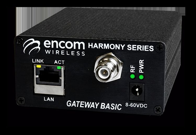
Harmony Gateway Basic User Manual

                                              Harmony Gateway Basic User Manual V2.0.0
                                                                             July 2020

                                        Email:             support@encomwireless.com
                                        Toll Free:                    1-855-730-1122
                                        Worldwide:                     (403) 230-1122
                                        Web:                  www.encomwireless.com

                                    2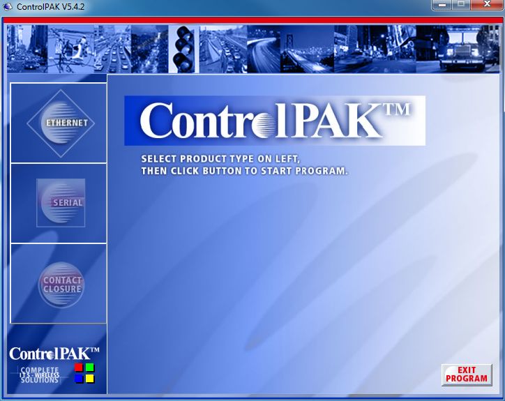
Harmony Gateway Basic User Manual

3
Harmony Gateway Basic User Manual

                                                            TABLE OF CONTENTS

        WARNINGS AND PRECAUTIONS ................................................................................. 6
        INTRODUCTION ......................................................................................................... 7
              THE HARMONY SYSTEM ....................................................................................................... 7
              HARMONY GATEWAY BASIC ................................................................................................. 7
              OVERVIEW ............................................................................................................................ 8
              ANTENNAS WITH GATEWAY BASIC UNITS............................................................................ 8
              ANTENNAS COMPATIBLE WITH HARMONY GATEWAY BASIC UNITS ................................... 8
        SYSTEM TOPOLOGY ................................................................................................... 9
        LED Indicators .......................................................................................................... 10
        INSTALLING CONTROLPAK™ ..................................................................................... 11
              TECHNICAL SPECIFICATIONS FOR INSTALLING CONTROLPAK™.......................................... 11
        CONFIGURING YOUR HARMONY GATEWAY BASIC ................................................... 12
              LAN CONNECTION AND STARTUP ...................................................................................... 13
              LAN SEARCH ....................................................................................................................... 14
                  REAL TIME LAN SEARCH .............................................................................................................. 14
                  LAN SEARCH TABS ....................................................................................................................... 15
                  CONNECT LIST ............................................................................................................................. 16
              CONFIGURING THE UNIT .................................................................................................... 19
                  BASIC SETTINGS TAB ................................................................................................................... 20
                  SYSTEM TAB ................................................................................................................................ 21
                  ALERT TAB ................................................................................................................................... 23
                  SNMP TAB ................................................................................................................................... 24
                  PROTOCOL TAB ........................................................................................................................... 25
                  CALENDAR TAB ............................................................................................................................ 26
                  SETTING UP THE REAL TIME CLOCK THROUGH PC TIME OR NTS SERVER ................................... 26
                  I/O MAPPING TAB ....................................................................................................................... 27
                  EVENT LOGS TAB ......................................................................................................................... 28
                  SECURITY TAB .............................................................................................................................. 29
        Appendix A: Upgrading/Downgrading Firmware ...................................................... 30
        Appendix B: RF Exposure .......................................................................................... 31
              FCC...................................................................................................................................... 31
              HEALTH CANADA ................................................................................................................ 31
        Appendix C: Declaration of Conformity .................................................................... 32
              FCC...................................................................................................................................... 32
              WARNING (PART 15.21) ..................................................................................................... 32
              INDUSTRY CANADA ............................................................................................................ 32

                                                                                  4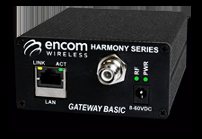
Harmony Gateway Basic User Manual

5
Harmony Gateway Basic User Manual

WARNINGS AND PRECAUTIONS

The following symbols indicate important safety warnings and precautions throughout this manual:

                        WARNING indicates that serious
                        bodily harm or death may result
                        from failure to adhere to the
                        precautions.

                        CAUTION indicates that damage
                        to equipment may result if the
                        instructions are not followed.

                        NOTE indicates certain conditions
                        that the user should be aware of.

                                                            6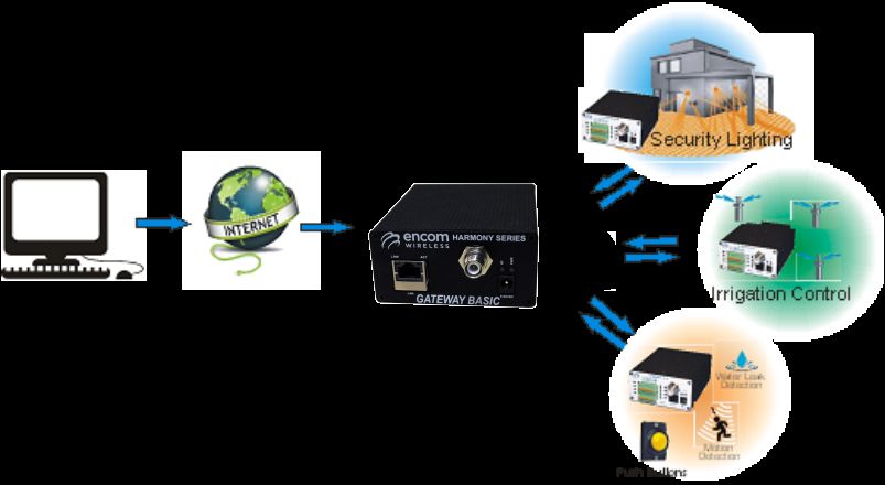
Harmony Gateway Basic User Manual
INTRODUCTION
THE HARMONY SYSTEM
The HARMONY line of devices allows you to monitor The Harmony Gateway Basic is fully compatible
and control field equipment from the comfort of your with our STRATOS Elite central software. With
network operations center. this powerful application, you can configure,
manage and monitor Gateway Basic devices
Just install a HARMONY I/O device at a remote site for
along with all other HARMONY devices.
immediate access to your equipment’s status, and
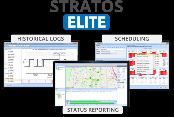
easily control your equipment using STRATOS Elite, our
complete network visualization management system. Use STRATOS Elite Central Software to:
Reduce your operating costs by eliminating costly site § Get a quick overview of your field devices
visits. Everything you need to know about the site is using a friendly map display
now available at your fingertips. § View the real-time status of your field
equipment
Harmony devices are used for applications such as: § Get e-mail alerts for important events and
§ School zone flasher control and monitoring alarms
§ Solar power system monitoring § Log equipment status information for later
§ Traffic cabinet monitoring review
§ Signage control § Schedule periodic on/off events using a
§ Gate control powerful schedule editor
§ Irrigation control and monitoring
§ Water/wastewater control and monitoring
§ Streetlight monitoring
§ SCADA applications
§ Any other application where remote equipment
needs to be monitored and controlled
HARMONY GATEWAY BASIC
The Harmony Gateway Basic is a compact master radio
with functional expandability through connection to
any Encom remote radio.
The device allows you to monitor Harmony devices
from a user-friendly front panel.
A simple web-based interface lets you configure,
control and check the status of the device. No extra
software is required.
7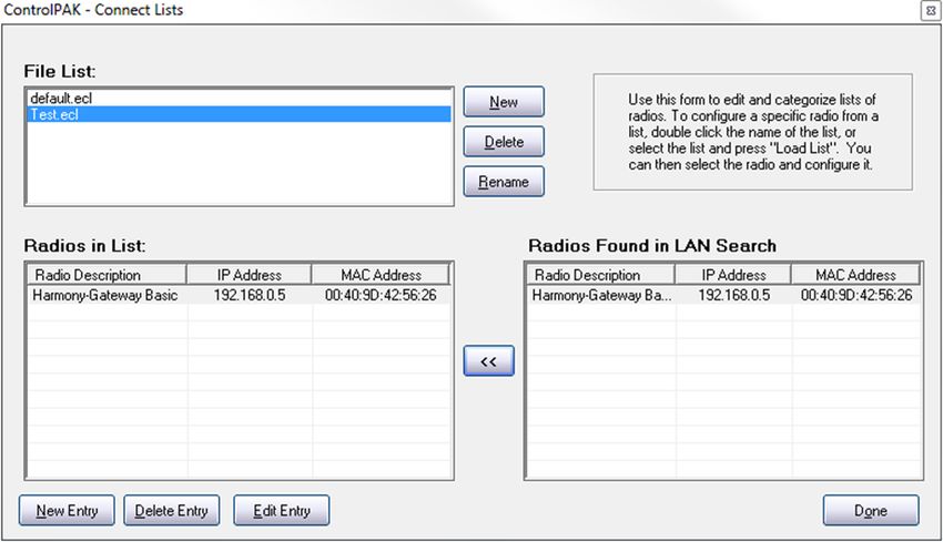
Harmony Gateway Basic User Manual

 OVERVIEW
 This manual is a guide and reference for programming
 Harmony Gateway Basic radios using Encom’s
 ControlPAK™ programming and diagnostics software.
 It contains instructions, suggestions, and information
 which guide you to set up and achieve optimal
 performance from your equipment.
 For network monitoring and control functions, please
 refer to the STRATOS Elite manual for details.

 ANTENNAS WITH GATEWAY
 BASIC UNITS
 Integrated 900MHz wireless communication is an
 option for Harmony Gateway Basic devices, designed
 with a reverse polarity TNC female antenna connector.
 NOTE: An antenna is not supplied with the unit. To
 order an antenna, please contact your local Encom
 Wireless dealer or email at sales@encomwireless.com.

 ANTENNAS COMPATIBLE WITH
 HARMONY GATEWAY BASIC
 UNITS
 There are 2 types of antennas typically used for
 Harmony Gateway Basic systems:
    § Yagi antenna
    § Omni antenna

 Other types of antennas can be used if your system has
 special requirements. Again, please reach out to us at
 sales@encomwireless.com to discuss any unique
 application needs or challenges.

                                                          8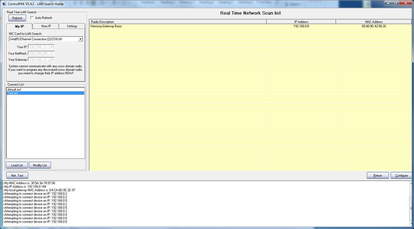
Harmony Gateway Basic User Manual

SYSTEM TOPOLOGY
The primary topology that the Harmony Gateway Basic supports is Networked Mode.

Networked Mode is used to set up for communication with STRATOS. This allows connected devices to be
monitored and controlled anywhere an internet connection is available.

                                                   9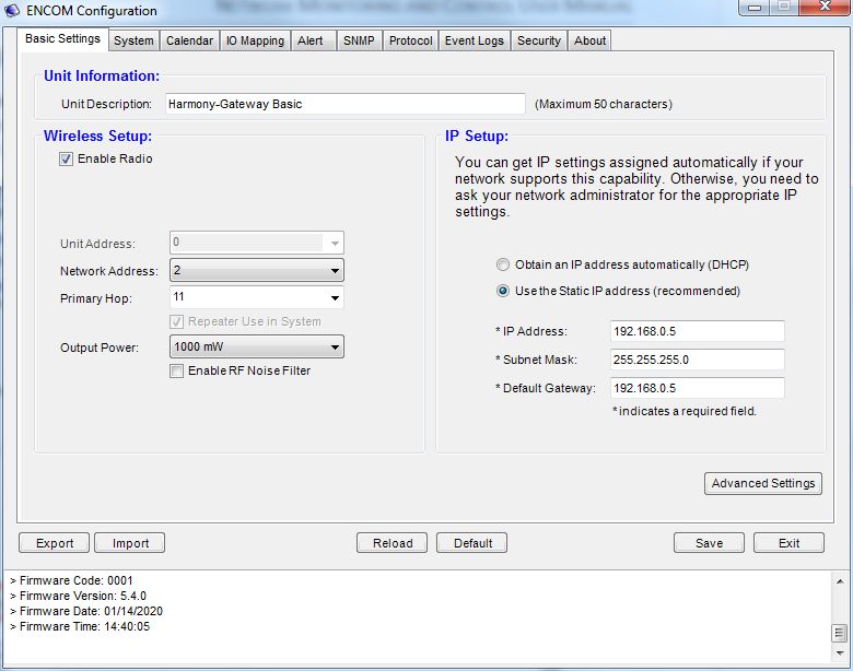
Harmony Gateway Basic User Manual
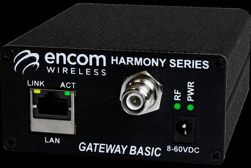
LED INDICATORS
There are four LED indicators on your Harmony
Gateway Basic radio as follows:
Ø PWR LED: Indicates the radio is powered ON.
Ø RF LED: Indicates the radio is linked and
communicating. There are two modes of
behavior that the RF LED will have based on the
connection between two HARMONY devices
(Gateway E-Lite 450, Gateway Advanced,
Harmony IP I/O8, SBX Remote I/O):
Ø LED stays ON: If the RF LED stays on,
then the Gateway Basic can
communicate reliably with another
Harmony device.
Ø LED is blinking: If the LED is blinking,
then there is an issue blocking device
communication.
10Harmony Gateway Basic User Manual
INSTALLING
CONTROLPAK™
Before you can configure your Harmony Gateway After downloading the latest version of the
Basic radio, you must first have the radio ControlPAK™ software:
connected to your computer and ControlPAK™ must
be installed on the same computer. 1. Click Setup
The ControlPAK™ Install screen appears.
You can download the most recent version of 2. Click Next.
ControlPAK™ from our website at: The ControlPAK™ Software License Agreement
screen appears.
https://www.encomwireless.com 3. Click I agree, and then click Next.
The Upgrade/Uninstall screen appears.
4. Click Next.
Ensure you are using ControlPAK™ version 5.4.2 or The Select Directory screen appears.
higher. 5. Enter the directory in which you would
like the ControlPAK™ software to install or
click Next to accept the default directory.
TECHNICAL SPECIFICATIONS The Start Copying Files screen appears.
6. Click Next.
FOR INSTALLING The Setup file copies the appropriate
CONTROLPAK™ files to your computer, and then
registers the software.
Minimum requirements for installing ControlPAK™ 7. Click Next, then click Finish.
on your PC: The ControlPAK™ icon then appears on
your desktop.
• Windows XP or Windows Vista
• 1GB RAM
• 100 MB free hard drive space
• Microsoft .NET framework 2.0
At this point, ControlPAK™ has been successfully
installed.
11Harmony Gateway Basic User Manual
CONFIGURING YOUR HARMONY GATEWAY BASIC
The first step in using ControlPAK™ to configure your radio is to enter the correct configuration mode.
There are three configuration mode options available from the main screen:
• ETHERNET
• SERIAL
• CONTACT CLOSURE.
12Harmony Gateway Basic User Manual
LAN CONNECTION AND STARTUP
NOTE: A straight through Ethernet cable is required to connect the Harmony Gateway Basic to a switch, a hub,
or the computer on which ControlPAK™ is installed.
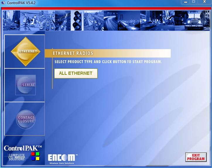
On your desktop, double click the ControlPAK™ icon to start the software.
Click on Ethernet, then click All Ethernet to start the system discovery process.
13Harmony Gateway Basic User Manual
LAN SEARCH
To program a Gateway Basic radio, it must first be ‘discovered’ by ControlPAK. This means the Gateway Basic
must be physically connected to your Ethernet network, or connected directly to the computer on which you
are running ControlPAK. The Real Time Network Scan list results screen (shown above) is the root menu which
displays the ‘discovered’ radios in the network and allows the selection of, and access to, a specific radio for
programming. When programming of that radio is complete, you are returned to the Real Time Network Scan
list screen, where you can continue selecting and configuring each of your radios and repeating the configuration
steps.
REAL TIME LAN SEARCH
If you do not see your radio listed, click the Refresh button to update the list. When you program a radio as
outlined in the following pages, the radio will be reset, and the software will return to this page. At that point,
the radio will still be completing its reboot process and will not be shown on this screen. Wait about one minute,
then click Refresh and the complete list will be shown. You can also select another radio and go through its
configuration process while other radios are rebooting.
Click the Auto Refresh check box to have the ControlPAK™ software automatically refresh the LAN search. The
interval for running the Auto Refresh can be set as desired.
14Harmony Gateway Basic User Manual
LAN SEARCH TABS
Use the LAN Search tabs to find your radio based on IP, configure search parameters, and define a static IP for
your radio as desired.
Each of these tabs are defined as follows:
Ø My IP
§ If your computer has multiple network interface cards [NIC], select the desired network interface on this
menu.
§ The IP, NetMask and Gateway addresses will be shown for the selected NIC card.
Ø New IP
§ This menu is used to change the radio’s IP, Subnet Mask and Gateway addresses.
Ø Settings
§ Enter the LAN Search Time interval. Enter a longer search time if you are having trouble finding a radio.
15Harmony Gateway Basic User Manual
CONNECT LIST
A Connect List file is used in instances where your Harmony Gateway Basic radios are part of a different IP
network and need to be accessed. This list could include all or only specific radios in a network. Each Connect
List is saved as a specific file.
LOAD LIST
The Load List button ‘loads’ a Connect List ‘file’. First, select the desired Connect List (.ecl), then click the Load
List button. The list of radios found will be displayed on the right (yellow background) under the Real Time
Network Scan List.
1
2
16Harmony Gateway Basic User Manual
MODIFY LIST
The Modify List button allows you to create, edit and categorize lists of radios.
§ To modify an existing Connect List, select (click) your file from Connect List file and then click the Modify
List button.
Select 1
from list
2
§ To create a new Connect List, click on the Modify List button and you will be taken to the Connect List
creation screen shown below.
Ø Creating a New List
Click on the New button to create a new Connect List file. A screen will display asking you to type in a name for
your new Connect List. Once you’ve entered a name and clicked OK, you will then see the Connect List file name
you created appear in the File List section.
17Harmony Gateway Basic User Manual
Once a new Connect List file name is created, you can then add radios to the list from the Radios Found in LAN
Search section.
To add radios to your Connect List, select the newly created Connect List file from the File List section, select the
radio in the Radios Found in LAN Search section and then click the double arrow ( ) button to the left of
the Radios Found in LAN Search section. This will add the radio to the Radios in List section.
• New Entry – If a radio was not found during the initial Real Time Network Scan, you can manually add the
radio to the Radios in List section by clicking on the New Entry button. The window below will then be
displayed. Enter the radio’s IP address and then click the Find button. If the radio is found, you can then click
on the OK button to add it to the Radios in List section.
• Delete Entry – To remove a radio from the Radios in List section, click on the radio to select it and then click
on the Delete Entry button.
• Edit Entry – You can also edit any of the radios shown in the Radios in List section by selecting it and then
clicking on the Edit Entry button. This will allow you to edit the radio’s IP Address, Description, MAC Address
(optional) or select a different radio model from the dropdown list.
• Done – When you have the desired radios in the Radios in List section, click on the Done button in the
bottom right corner. You will be taken back to the ControlPAK™ LAN Search Home screen. You can then
select the Connect List from the Connect List section and then click the Load List button. If a Connect List is
properly selected, the right side of the window displays the list of radios with a yellow background.
Ø Deleting Lists
Selecting a Connect List and clicking the Delete button will delete the selected Connect List file.
18Harmony Gateway Basic User Manual
CONFIGURING THE UNIT
The ENCOM Configuration window allows you to configure several different parameters on your Gateway
Basic. This section will focus on the details of each parameter, which can be customized to best suit your
system`s needs.
Function Button Description
Export existing configurations to an encrypted file.
Import encrypted configuration data from an Exported file into ControlPAK.
(NOTE: The radio is not programmed until the Save button is clicked.)
Reload current configuration data from the radio into ControlPAK.
Save configuration data to a radio’s internal memory.
Sets radio with factory default parameters.
(NOTE: The radio is not programmed until the Save button is clicked.)
Return to the LAN Search screen to program another radio, check System status
or return to the ControlPAK™ login screen
19Harmony Gateway Basic User Manual
BASIC SETTINGS TAB
The Basic Settings page allows you to configure your radio’s name, network address, hop pattern, output
power, and the IP setup:
Section Field Name Description
Unit Unit Description Enter a description (max. 50 characters). The radio description name
Information you enter displays in the Real Time Network Scan list.
Wireless Unit Address This field will be greyed out as the system defaults the Master radio to a
Setup unit address of 0. This cannot be overridden.
Network This lets you select an address number that is associated to a particular
Address radio network. By default, this is set to 0. If you have more than one
network, it is recommended to have a different address for each
network. The network address needs to match in each radio in the
particular network for proper communication.
Primary Hop This lets you select a hop pattern value for the network. By default, this
Pattern is set to 11. It is recommended to select a value that is different from
the hop pattern of other Encom equipment. The primary hop pattern
needs to match in each radio in the particular network for proper
communication.
Repeater Use in Click this checkbox to enable a HARMONY device to function as a
System Repeater in your system. This option is greyed out for Gateway devices.
Output Power Output Power is adjustable from a minimum of 1mW up to a maximum
of 1W.
Enable RF Noise Click this checkbox to enable the RF Noise Filter if the system has a
Filter strong receive signal. This will improve data integrity.
IP Address Obtain an IP Your radio requires an IP Address to communicate through the Ethernet
Setup Address LAN Port.
automatically Use the Obtain an IP address automatically (DHCP) option to
(DHCP) automatically assign an IP Address to your radio.
Use the Static IP Use this option when you need to manually enter the IP Address,
address Subnet Mask, and Default Gateway information provided by your I.T.
(recommended) department.
If you are configuring a new radio, then continue to the System tab.
If you are editing an existing radio configuration and would like to save your new configuration to a file (to
share with other radios on your network), click Export, then click Save to upload the new configuration to the
radio.
20Harmony Gateway Basic User Manual
SYSTEM TAB
In order for the Gateway Basic to communicate with other HARMONY devices on a particular network, a
system needs to be created. During this step, the HARMONY devices that are communicating are added in.
During the system setup, the schedule number that is to be used per device is to be added in during the
creation of the system.
From the Beacon Flasher section, click the Add button. This will enable the section to be active allowing you to
enter the details for a HARMONY device.
Type a user defined name for the HARMONY device in the Name field.
Select the Schedule Number that is to be associated with the HARMONY device being entered.
21Harmony Gateway Basic User Manual
Enter a Description for the HARMONY device–this may be the location where the device is installed.
Press the Apply button to add this entry to the list. Repeat these steps for each HARMONY device that is to be
linked to your Gateway Basic. The list will show the entire system.
22Harmony Gateway Basic User Manual
ALERT TAB
In the Alert tab, you can configure your Gateway Basic to send out an alarm when an event has occurred
(either involving a setting or system change, or a situation that requires maintenance). The different
alarms and events that can be reported are shown below.
Events for which the Gateway Basic can send alarms are listed below with corresponding descriptions.
Note that some of these events are self-explanatory:
• Override Changed The addition or removal of an override
• Input Changed (not available in Harmony Gateway Basic)
• Output Changed (not available in Harmony Gateway Basic)
• Low Battery (not available in Harmony Gateway Basic)
• Lamp Failed (not available in Harmony Gateway Basic)
• A/C Lost (not available in Harmony Gateway Basic)
• Solar Panel Disconnected (not available in Harmony Gateway Basic)
• Battery Disconnected (not available in Harmony Gateway Basic)
• Configuration Changed Change(s) in the Gateway Basic’s configuration or settings
23Harmony Gateway Basic User Manual
SNMP TAB
The SNMP tab allows your Gateway Basic to be configured for use in an SNMP-based network. Note that you
must activate the Enable SNMP Operation option by clicking the checkbox to configure SNMP settings.
The settings specific to SNMP operation are described below:
• SNMP General Setup – Allows you to set up general SNMP settings
o Read/Write Community Name: The name (or string) that permits access to device information
o Trap Version: Select the SNMP version(s) of the trap messages generated from your Gateway Basic
o Trap Manager Host IP: IP address of your Trap Manager software
o Trap Community Name: string included when Gateway Basic sends Traps to your Trap Manger
software
• SNMP V3 Setup – Allows you to set up settings specific to SNMP V3
o User Name: Login name to access your Gateway Basic’s SNMP information
o User Authentication Level: Select the level of security desired for the SNMP network
o Authentication Password: Password used to confirm user identity
o Privacy Password: String used to encrypt SMNP V3 messages
24Harmony Gateway Basic User Manual
PROTOCOL TAB
The Protocol tab allows you to set up the communication method / protocol between your Gateway
Basic and STRATOS I/O.
The Protocol tab contains the following settings:
• Gateway Protocol Mode – This setting controls the method of communication.
o Polling – this option causes STRATOS I/O to query or ‘poll’ the status of this device at fixed time
intervals. This can be configured in STRATOS.
o Report by exception – Select this option if your Gateway Basic is set up in a cell modem-based
network. With this option selected, Gateway Basic will initiate communication with STRATOS
I/O when any one of the enabled events occurs.
These sections are required if your Protocol Mode is set to Report by Exception.
• Report Settings
o Server IP Address: The IP address of the STRATOS I/O network you want your device to connect to
o Server IP Port: The IP port of the STRATOS I/O network you want your device to connect to
o Heartbeat Interval: The time interval (in seconds) your Gateway Basic sends update packets to
STRATOS I/O regardless of its current event status
• Communication Settings
o Packet Size: Controls the size of the status message. It is strongly advised leave this value at 1400.
25Harmony Gateway Basic User Manual
CALENDAR TAB
The Calendar tab allows you to set the clock of your Gateway Basic manually, use the clock of your
connected PC to set up time, or connect to a Network Time Server to ensure that you constantly have
the correct time set anywhere.
SETTING UP THE REAL TIME CLOCK THROUGH PC TIME OR NTS SERVER
It is recommended that you contact your I.T. department to obtain a
primary and secondary network time server to use with the Gateway Basic.
With different PC’s, different times can occur and result in an
inaccurately scheduled time operation for your system.
The Gateway Basic clock is to be synchronized for the scheduled times to turn on or off as desired. If
the Time Zone is not correct or the PC time has changed, it will affect the turn on time.
1. Click the Use PC Time to update clock box, if you want to use PC clock for automatic update.
2. Press the Update Now button to immediately synchronize the time with your PC.
3. Place a check mark in the Network Time Server Enable box, if you want Gateway Basic to obtain
time updates from the specified Primary or Secondary Network Time Server (NTS) automatically.
26Harmony Gateway Basic User Manual
I/O MAPPING TAB
I/O MAPPING SETUP
The Gateway Basic unit supports the use of a hard-switch for wireless on/off control over the 900MHz network
and/or over IP-based LAN network with all Encom HARMONY devices.
If the Enable LAN I/O Mapping Forwarding check box is active (checked), the I/O mapping message from one
system will transfer to other systems over the IP based LAN network. This allows one or more OUTPUT from
one system to mirror the status of any INPUT from the same or different systems.
o Multicast IP Address: IP Address used to transfer I/O message over the LAN network
o Multicast IP Port: IP Port used to transfer I/O message over the LAN network
(For successful communication, the Multicast IP Address and Multicast IP Port need to be identical in all
Gateway devices across the network.)
27Harmony Gateway Basic User Manual
EVENT LOGS TAB
The Event Logs tab allows you to record data concerning the conditions and performance of your overall
system. You can setup the Event Log to record general information, warnings and errors in the log entries, as
well as what specific events get recorded.
28Harmony Gateway Basic User Manual
SECURITY TAB
The Security Tab is where the user name and password for a radio can be configured. This ensures only
authorized personnel are able to make changes to radio settings.
29Harmony Gateway Basic User Manual
APPENDIX A: UPGRADING/DOWNGRADING
FIRMWARE
1. Connect to the Gateway Basic unit using ControlPAK™ and switch to the About tab.
2. Click the Firmware Upgrade button.
3. Accept the Firmware Upgrade License Agreement.
4. Read the warning message, check the box that says you have read and understand the warning and then
click the Next button.
5. Select the firmware version to upgrade or downgrade to, click the Next button. A progress bar will show
the status of the upgrade or downgrade.
6. After the upgrade or downgrade completes, the software will automatically disconnect the radio. Re-
connect the radio and navigate to the About screen and confirm that the Harmony Gateway Basic unit now
has the correct firmware version.
30Harmony Gateway Basic User Manual
APPENDIX B: RF EXPOSURE
FCC
FCC Regulations allow up to 36 dBm effective radiated power (ERP). Therefore, the sum of the transmitted
power (in dBm), the cabling loss and antenna gain cannot exceed 36 dBm.
Ø 1mW = 0 dBm
Ø 10 mW = 10 dBm
Ø 100 mW = 20 dBm
Ø 1000 mW = 30 dBm
When transmitting 1 Watt (30 dBm) and the cable and connector losses are 2 dB, the antenna gain cannot
exceed 36 - (-2) - 30 = 8 dBi.
If an antenna with a gain higher than 8 dBi were to be used, the power setting must be adjusted accordingly.
HEALTH CANADA
The installer of this radio equipment must ensure that the antenna is located or pointed such that it does not
emit an RF field in excess of Health Canada limits for the general population; consult Safety Code 6, available
from Health Canada’s website:
Safety Code 6: Health Canada's Radiofrequency Exposure Guidelines
31Harmony Gateway Basic User Manual
APPENDIX C: DECLARATION OF CONFORMITY
FCC
This device complies with Part 15 of the FCC rules. Operation is subject to the following two conditions:
(1) This device may not cause harmful interference.
(2) This device must accept any interference received, including interference that may cause undesired
operation.
WARNING (PART 15.21)
Changes or modifications not expressly approved by the party responsible for compliance could void the users’
authority to operate the equipment.
INDUSTRY CANADA
This device complies with Industry Canada’s RSS-210 specifications.
32Harmony Gateway Basic User Manual
ENCOM Wireless provides field-proven, cost-effective wireless data solutions
for municipal and industrial clients, with applications in the areas of:
Intelligent Transportation Systems
Public safety communications
Municipal corporate security and IT networks
Water and wastewater management
Electrical utilities
Oil and gas
Encom Wireless Data Solutions Inc.
#7, 640 - 42 Avenue NE
Calgary, AB T2E 7J9
Canada
Toll-free 1-855-730-1122 | Canada (403) 230-1122
Email: sales@encomwireless.com
www.encomwireless.com
33You can also read