Inter Technology Load Balancing Algorithm for Evolved Packet System
←
→
Page content transcription
If your browser does not render page correctly, please read the page content below
Inter Technology Load Balancing Algorithm for
                 Evolved Packet System
                                Marek Skowron, Suneth Namal, Jani Pellikka, Andrei Gurtov
                                           Centre for Wireless Communications
                                            University of Oulu, P.O. Box 4500,
                                                 FI-90014 Oulu, Finland
               marek.skowron@ee.oulu.fi, gkarunar@ee.oulu.fi, jani.pellikka@ee.oulu.fi, andrei.gurtov@ee.oulu.fi

   Abstract—In this paper, we present an advanced load balancing                            II. R ELATED W ORK
algorithm for Evolved Packet System utilizing different radio in-
terfaces. By using the fact that Evolved Packet Core can support,
                                                                          Load balancing algorithms have been studied in a number of
in addition to LTE also multiple other packet data technologies,       papers. In [2] system level load balancing algorithm developed
such as WLAN, we can utilize this additional dimension for             in SOCRATES project has been discussed and its network
benefit of load balancing for future mobile broadband networks.        performance has been evaluated. In [3] authors present how
The main goal of the algorithm is to minimize the number               a simple distributed intra-frequency load balancing algorithm
of unsatisfied users in the network and thus load balancing
algorithm is only active if those are present. We show a significant
                                                                       based on automatic adjustments of handover thresholds can
performance boost in network resource utilization and average          reduce call blocking rate and increase cell-edge throughput in
data rate per user when employing the algorithm.                       LTE. In [4] authors propose an Autonomic Flowing Water
   Index Terms—EPS, load balancing, LTE, WLAN, FAP, Self-              Balancing Method, which detects overload conditions and
Organizing Networks.                                                   adjusts handover hysteresis margin for eNBs and triggers
                                                                       handover behaviors to balance load. In this paper, we focus
                                                                       less on the adjustment of handover parameter and focus on
                       I. I NTRODUCTION                                improving the performance using other radio interfaces.
   In recent years the amount of users using mobile services                             III. E VOLUTION OF EPS
has grown very noticeably. It is said that by the year 2020               The rapid growth of internet and packet data services in last
there will be a thousand-fold increase in mobile broadband             few years called for a need for evolution of core network (CN).
traffic [1]. With such a huge growth in numbers we need                The CN of 3GPPs Universal Mobile Telecommunications
to focus our attention on managing network users in wise               System (UMTS) has been under development for last few
manner. Load balancing (LB) is a novel concept in which we             years. The progression of the core network is called System
can transfer users between base stations for more balanced             Architecture Evolution (SAE) and resulted in Evolved Packet
load distribution in order to maintain appropriate end-user            Core (EPC). There are numerous benefits of SAE including
experience and network performance.                                    flat architecture with less network nodes, smaller delays and
   LB is part of the Self-Organizing Networks (SON) solu-              bigger data rate support.
tions. The concept behind SON is to automatize the adjustment             The radio access part has also been under development. This
of parameters of the network in order to adapt to the current          process is called Long Term Evolution (LTE) and the outcome
situation and network conditions and boost the performance.            is called Evolved UMTS Terrestrial Radio Access Network
The main idea of LB is to transfer users from overcrowded              (E-UTRAN). As E-UTRAN is solely packet-data based, EPC
cells to less heavily loaded, so it is possible to use radio           also provides the IP connectivity to non-3GPP radio access
resources more efficiently across the network. In this paper           network (RAN) domains such as WLAN or WiMAX. More
we are presenting a load balancing algorithm which could be            detailed description of SAE and LTE can be found in [5].
used in future wireless networks. Algorithm can minimize the              The data flow in EPS, between EPC and different radio
number of unsatisfied users in a network by means of proper            access technologies (RATs), is provided by two primary gate-
load balancing and advance resource provisioning. The re-              ways. User data is transmitted from E-UTRANs base stations
mainder of this paper is organized as follows. Section II briefly      (eNodeBs) to EPC through Serving Gateway (S-GW). It is
describes papers related to this work. In Section III evolution        also an anchor point for intra-LTE mobility, as well as between
of core and radio access network is presented. Section IV              GSM/GPRS, WCDMA/HSPA and LTE. Packet Data Network
focuses on different handover (HO) procedures supported by             Gateway (PDN GW) is a user plane node connecting EPC
EPC. Section V presents our simulation environment. Section            to the external IP networks and non-3GPP services. Another
VI focuses on description of the load balancing algorithm.             important node is Mobility Management Entity (MME). It is
Section VII presents results of simulations. Finally Section           responsible for managing all control plane functions related
VIII presents conclusions and future work related to this topic.       to subscriber and session management, assigning the network
resources and handling, among others, handovers (HOs) [6]. handover source eNB (SeNB) and target eNB (TeNB) prepare
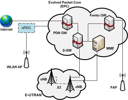
The Figure 1 presents EPS architecture together with other and execute the handover, at the end asking MME to switch
supported RANs. Note that only key nodes for this paper are the DL data path from SeNB to TeNB. MME asks S-GW to
shown. switch data path towards new eNB. Packet forwarding is also
done via X2 interface. Intra E-UTRAN handover is presented
in Figure 2 [7].
Fig. 1. Evolved Packet Core (EPC) architecture.
IV. M OBILITY IN EPS
In this paper the types of handovers we are focusing on Fig. 2. Intra E-UTRAN Handover.
are intra E-UTRAN (LTE), E-UTRAN to Femtocell and E-
UTRAN to WLAN. First we are describing shortly a generic As in generic description there are preparation, execution
steps present in every type of handover and in later subsections and completion phases present here. EPC entities are not
we’ll present each handover procedure in more details. involved in the preparation phase and only X2 interface is
The main idea behind a handover (or handoff) is to maintain used. During preparation phase SeNB additionally establishes
a continuous data session while being transferred to different UL and DL data forwarding paths for U-plane traffic towards
cell. In every handover procedure there’s a source cell, which TeNB. In the execution phase SeNB forwards buffered DL
UE moves from, and the target cell which UE moves to. The packets from S-GW to target eNB. After UE has connected to
nodes in cells are also called accordingly. TeNB, TeNB sends Path Switch Request to MME informing
In general, all handovers are divided into preparation and ex- that UE has changed cell. S-GW switches the DL data path
ecution phase. During preparation phase target cell is informed to the target side. It also sends End Marker to the SeNB to
about the handover and appropriate resources (if available) are inform about the end of data transfer. TeNB sends UE Context
allocated in both target RAN and core network. Execution release message to inform about successful handover. A more
phase can be further divided into execution and comple- detailed description can be found in [7].
tion phases. During those phases downlink (DL) packets are
buffered or forwarded to target cell. UE performs the handover
B. E-UTRAN to WLAN
and establishes connection with target RAN and core network.
Source CN is informed of HO completion, forwards buffered LTE to WLAN mobility is a generic one (also called non-
packets to target CN and resources are released in source RAN. optimized HO) meaning it is not optimized to any access
technology. It is therefore easier to apply to any non-3GPP
A. Intra E-UTRAN interface. There’s also no interaction assumed between the two
Intra RAT handover is performed between eNBs in E- access networks. The most important in E-UTRAN to WLAN
UTRAN. In E-UTRAN there are two types of intra E-UTRAN handovers is the preservation of the IP address to maintain the
handovers, intra and inter MME/S-GW. In the latter one a connection while being transferred between cells. Mobile IP
handover to different MME/S-GW is additionally performed. has been designed by Internet Engineering Task Force (IETF)
However for simplicity we’ll focus only on the first case. to address this issue. With the help of Mobile IP UE is able to
A benefit of SAE that hasn’t been yet mentioned in the EPS connect to other IP radio access while keeping the connection
description is the X2 interface. Through this interface eNBs to home network (EPC) through tunneling of IP packets.
in E-UTRAN can directly communicate between each other, Mobile IP: There are two mobility concepts in EPS: host-
without entities in EPC being involved. This communication based (client-based) and network-based [8]. In the first one
is used among other in case of handovers. In the X2 based UE (host) is involved in mobility signaling and movementdetection. The latter one means that the network is responsible
for signaling and detection of UE movement.
Every device in EPS is assigned an IP address, which is part
of a sub-network. In order to be able to receive packets while
being in another network (e.g. when UE switches from 3GPP
to WLAN) Mobile IP introduces Home Agent (HA) entity to
PDN-GW. The function of HA is to associate the original IP
address, Home Address (HoA) with the local address in the
foreign network, Care of Address (CoA) and forward packets
addressed to HoA to CoA. Route optimization (RO) is not
supported in EPS which means that also uplink packets have
to be sent via HA [8].
Mobile IP is specified for both IPv4 (Mobile IPv4 - MIPv4)
and IPv6 (MIPv6). There also exists Dual-Stack Mobile IP
(DSMIPv6) which supports dual-stack IPv4/IPv6 operation.
Those protocols are host-based. An example of network-based
protocol is Proxy Mobile IPv6 (PMIPv6). It was created for
those UEs which don’t have Mobile IP functionality and hence
mobility agents in the network (which act as proxies) track the
movement of UE and execute signaling of IP mobility instead
of UE [8], [9].
Fig. 3. E-UTRAN to Femtocell handover.
In case of DSMIPv6, WLAN network assigns the UE new,
local IP address. When dealing with untrusted WLAN net-
work, meaning that 3GPP operator, which owns PDN GW and
HSS, doesn’t trust the security of WLAN, an IPSec encrypted
tunnel has to be established between UE and Enhanced Packet
Data Gateway (ePDG) - see Figure 1. The new local IP address
is used as CoA within EPS. The exact procedure has been
described in section 12.4.3 in [8].
Handovers between different WLANs are also possible
while still having access to EPC, however it is outside of the
scope of this paper. More details can be found in [8].
C. E-UTRAN to Femtocell
Femtocells are relatively small, support only small number
of users (typically 2-6) and have coverage of only tens of
meters. In this paper we consider femtocells supporting LTE
access. In the future we can expect many Home eNBs (HeNBs)
deployed with LTE support. The reason for this is that Femto
Access Points (FAPs) are easier and cheaper to roll out that
normal-size base stations and basically anybody can establish
one. Thus it is expected that LTE will be rolled out in
femtocells first [10].
We can distinguish three types of handovers including Fig. 4. Femtocell to E-UTRAN handover.
femtocells: hand-in (E-UTRAN to FAP), hand-out (FAP to
E-UTRAN) and inter-FAP. In this paper we will focus on first
two because inter femtocell mobility is out of the scope of
this paper. Procedures for hand-in and hand-out handovers are main reasons for increased complexity as compared to Intra-
presented in Figure 3 and Figure 4 respectively [11]. LTE mobility. Therefore messages (e.g HO request messages)
When describing mobility including femtocells a new node are routed through MME and Femto GW. This increases the
has to be introduced, namely Femto Gateway (Femto GW signalling overhead associated with this type of handover.
or HeNB GW). It is an intermediate node between EPC and Complexity is also increased by admission control. Because
HeNBs. Femto GW acts as a virtual eNB with eNB ID and as of Closed Subscriber Group (CSG) authorization checks have
such is recognized by MME. However there’s no X2 interface to be performed during the HO, as not every UE has access
between Femto GW and other eNBs. This is one of the to every FAP [11].V. S YSTEM M ODEL them. First algorithm considers handover to different poten-
tial TeNBs, since this type of handover uses least network
We have developed a Matlab based simulation model to
resources. Potential TeNB with smallest amount of used PRBs
evaluate our proposal on load balancing. The simulation envi-
is chosen in order to make the PRB load as ”flat” as possible
ronment consists of NeN B LTE base stations and NU E users.
across eNBs. However if there are no potential TeNBs, or
Additionally there are NW LAN and NF AP WLAN and Femto
all potential TeNBs are overloaded, users will be transferred
Access Points, respectively with random number of ”own”
to WLAN AP or FAP, if they are in the coverage area. IEEE
(non LTE) users. For each time instant users move randomly
802.11n standard provides higher data rate than LTE FAP, thus
across the map and handovers between eNBs are performed
former is considered first. In case of high PRB load in eNB
if needed, based on current location and signal strength from
(above 70%) and user with high data rate (above 50 PRBs)
eNBs. In each time instant, the speed of the mobile user is
handover to WLAN will be made (if possible) regardless of
selected from a range in-between 0-15 ms−1 alone a random
PRB availability in potential TeNBs.
direction. The signal strength is calculated using a path loss
There are no intra-WLAN or intra-FAP handovers, because
model.
the coverage of those do not overlap (for simplicity). We
Each user can be in one of three states: inactive state,
assume that all handovers are successful (if there are resources
meaning the UE is switched off and user is not connected
available in the target cell).
to network at all; active state, meaning the UE is switched on,
but there’s no ongoing voice call nor data transmission (can
VII. S IMULATION R ESULTS
be also called idle state); and connected state, meaning UE is
turned on and an active IP data transfer is ongoing (voice calls In order to evaluate the performance of the algorithm
in LTE are also IP based). At each time instant about 80% of number of simulations have been performed. Each simulation
users in the network are in active state and 30% of the users has been run for 1000 time instants. Each of 12 eNBs can
are connected (all connected users are also active users). From allocate up to 600 PRBs. According to 3GPP specifications
algorithm point of view we’re focusing on connected users. each user can use between 6 and 110 PRBs [12], which means,
When switching to connected state, each user is assigned that assuming that 30% of the users are in connected state,
a random duration time of connection and desired number of there are resources to satisfy about 450 users in the network
physical resource blocks (PRBs). Number of PRBs allocated (assuming each user in connected state uses about 50 PRBs
to the user determines its data rate. High number of desired which is an average value of the allowed PRB range). We
PRBs means user wants to e.g. stream high definition video, have measured the number of unsatisfied users for increasing
while low number of PRBs means user only wants to make a total number of users in the network and with increasing
voice call. For more details see [12]. WLAN and FAP coverage. Additionally overall PRB usage
Each eNB has a limited number of PRBs that can be in the network and average number of used PRBs per user
allocated to its users. If eNB is using less than 80% of its have been measured. The results are presented in Figure 5, 6
resources, newly connected users are allocated their desired and 7 respectively.
number of PRBs. If the 80% limit for the eNB is exceeded,
users are only allocated minimum possible number of PRBs
(which is 6 according to 3GPP specifications). This is done
in order to save resources for future potential users (e.g.
after handover from another eNB or switching from active to
connected state). In that case, if user has a demand for more
than the minimal value of 6 PRBs, they become unsatisfied.
VI. L OAD BALANCING A LGORITHM
The main goal of the algorithm is to minimize the number
of unsatisfied users in the network and thus load balancing
algorithm is only active if those are present. For each time
instant, every user in connected state is selecting potential
target eNBs (TeNBs), to which it can be transferred in case
the serving eNB is overloaded. Potential TeNBs are those with
SNR high enough to maintain current data rate of the user. Fig. 5. Unsatisfied users in the network.
Additionally if user is in a coverage area of WLAN AP or
FAP, those are also considered as potential target cells. As we can see in the first figure, there is a clear decrease
For each eNB with unsatisfied users, algorithm tries to move in number of unsatisfied users when employing only the
the users to different, less loaded eNBs or APs. Users with load balancing algorithm. The performance further improves
high PRB usage are considered first in order to minimize as coverage of WLAN and Femto APs increase. For 800
number of handovers and signalling overhead associated with users, with 20% WLAN and 10% FAP coverage number ofunsatisfied users drops by half and with 50% WLAN and 25% access points brings very noticeable improvements to the
FAP coverage it is reduced almost five times. performance of the algorithm and the system. The resources
of the network are used in more intelligent fashion which
results in much decreased number of unsatisfied users and
almost doubled average data rate per user for high congestion
case. Depending on the area some other radio access networks
could also be included (e.g WiMAX or HRPD, especially
considering North America or Asia).
Maximum simulated coverage of WLAN and FAP was 50%
and 25% respectively, however in the future, especially in
urban areas we can expect higher coverage than this, which
will increase the performance of the algorithm even more. Of
course we have to take into consideration that some WLAN
APs or FAPs can be unaccessible (e.g. private femtocells in
homes).
In current algorithm users are moving randomly across the
map, regardless of which radio technology they are using.
Fig. 6. Overall number of PRBs in the network. However in real life, if user is transferred to WLAN or FAP,
they may want to stay in the coverage area, because of the
When looking at the second figure, we can see that resources increased available data rate there (e.g. in case of 802.11n
of the network are used more extensively with LB algorithm, which offers higher data rate than LTE), which again will be
which means we can satisfy more users with the same available beneficial for the performance.
number of PRBs in the network. The number of used PRBs
ACKNOWLEDGMENT
decreases as the WLAN/FAP coverage increases due to the
fact that more users are being transferred to WLAN and Femto The simulations have been performed in framework of
networks and don’t use the EPC PRBs. Celtic MEVICO project. Authors would like to thank project
partners for fruitful discussions and their valuable advice on
writing this paper.
R EFERENCES
[1] Nokia Siemens Networks, 2020: Beyond 4G. Radio Evolution for the
Gigabit Experience, 2011, Nokia Siemens Networks White Paper.
[2] A. Lobinger, S. Stefanski, T. Jansen, I. Balan, “Load balancing in
Downlink LTE Self-Optimizing Networks,” in 71st IEEE Vehicular
Technology Conference Spring (VTC2010-Spring), May 2010.
[3] R. Kwan, R. Arnott, R. Paterson, R. Trivisonno, M. Kubota, “On
Mobility Load Balancing for LTE Systems,” in 72nd IEEE Vehicular
Technology Conference Fall (VTC 2010-Fall), September 2010.
[4] H. Zhang, X. Qiu, L. Meng, X.g Zhang, “Design of Distributed and
Autonomic Load Balancing for Self-Organization LTE,” in 72nd IEEE
Vehicular Technology Conference Fall (VTC 2010-Fall), September
2010.
[5] Pierre Lescuyer, Thierry Lucidarme, Evolved Packet System (EPS). The
LTE and SAE Evolution of 3G UMTS. John Wiley and Sons, 2008.
[6] Alcatel-Lucent, Introduction to Evolved Packet Core, 2009, an Alcatel-
Fig. 7. Average number of PRBs per connected user. Lucent Strategic White Paper.
[7] 3GPP, 36.300 Technical Specification. Evolved Universal Terrestrial
Radio Access (E-UTRA) and Evolved Universal Terrestrial Radio Access
Results depicted in the third figure also indicate evident Network (E-UTRAN); Overall description; Stage 2, ver 10.5.0 (2011-11).
[8] M. Olsson, S. Sultana, S. Rommer, L. Frid, and C. Mulligan, SAE and
improvement when using the algorithm. In case without the the Evolved Packet Core: Driving the Mobile Broadband Revolution,
load balancing, average PRB number per user decreases con- 1st ed. Elsevier, 2009.
stantly with increasing total number of users. Case with pure [9] S. Gundavelli, K. Leung, V. Devarapalli, K. Chowdhury, B. Patil, “Proxy
Mobile IPv6,” IETF RFC 5213, Aug. 2008.
LB algorithm shows clear improvement in the range up to [10] L. Wang, Y Zhang, Z Wei, “Mobility Management Schemes at Radio
about 500-600 users and again as the WLAN and FAP cov- Network Layer for LTE Femtocells,” in IEEE 69th Vehicular Technology
erage increases, so does the performance of the system. With Conference, VTC Spring, April 2009.
[11] A. Ulvan, R. Bestak, M. Ulvan, “Handover Scenario and Procedure in
high WLAN/FAP coverage there’s almost twofold increase in LTE-based Femtocell Networks,” in The Fourth International Confer-
average user data rate. ence on Mobile Ubiquitous Computing, Systems, Services and Technolo-
gies, UBICOMM, October 2010.
VIII. C ONCLUSIONS AND F UTURE W ORK [12] 3GPP, 36.211 Technical Specification. Evolved Universal Terrestrial
Radio Access (E-UTRA); Physical Channels and Modulation, ver 9.1.0
As can be seen from results the presented load balancing (2010-03).
solution is very beneficial. Addition of WLAN and FemtoYou can also read