OPENCOMMS WEB CARD USER MANUAL ENGLISH
←
→
Page content transcription
If your browser does not render page correctly, please read the page content below

OpenComms Web Card

                     User Manual
                          English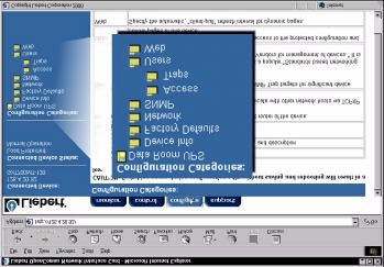
Table Of Contents
CONTENTS

ABOUT THIS USER MANUAL

QUICK START GUIDE

INTRODUCTION

INSTALLATION
Installing the Card
Connecting the Card to the Network
Configuring the Card

SERVICE TERMINAL
Opening a Service Terminal Connection
Main Menu
System Information Menu
Network Interface Menu
SNMP Communication Menu
Web Server Menu
Firmware Updates Menu
Factory Settings Menu

WEB
Opening a Web Connection
Connected Device Information
Security
Before Clicking Save and Reboot
After Clicking Save and Reboot
Monitor Tab
Control Tab
Configure Tab
Support Tab

SNMP

APPENDIX
Appendix A: MultiLink™ Configuration

SUPPORT AND CONTACT INFORMATION
Introduction
ABOUT THIS USER MANUAL
Welcome to the User Manual for the OpenComms Web Card. This man-
ual is available from Liebert's web site at www.liebert.com. The most
recent version is always located online and you should consult the Web if
you feel you have an older copy.

ABOUT THE QUICK START GUIDE
On the next two pages you will find a copy of the Quick Start Guide. The
Quick Start Guide ships in the box with the OpenComms Web Card and
provides the most important information you need to install and configure
of the card. It is included in this manual for your reference.

INTRODUCTION

The OpenComms Web Card delivers SNMP (Simple Network Manage-
ment Protocol) and Web support to the UPS in which it is installed. The
card is designed for use in a Liebert UPS with an Intellislot bay. This
include the PowerSure Interactive, UPStation GXT, UPStation GXT2U,
and Nfinity.

The OpenComms Web Card requires an Ethernet network connection
and supports both 10Mbit and 100Mbit communication speeds and either
half or full duplex.

The OpenComms Web Card enables in-band communication via the Web
from computers running web browser software.

The OpenComms Web Card enables in-band communication with net-
work management systems (NMS) via SNMP.

The OpenComms Web Card integrates with Liebert's MultiLink™ soft-
ware to provide notification for unattended, graceful operating system
shutdown of PCs, servers, and workstations. MultiLink is available for
most operating systems. For more information on MultiLink and a down-
loadable version of MultiLink software please visit www.liebert.com.
INSTALL
· Locate the Intellislot bay on the back of your
  Liebert PowerSure Interactive, UPStation GXT, or
  Nfinity UPS (Use the Intellislot labeled COM1).
· Remove the plastic Intellislot cover.
· Insert the OpenComms Web Card into the
  Intellislot bay.
· Secure the card with the previously removed
  screws.
· Connect Ethernet cable.

DHCP: The card ships with DHCP service enabled. The MAC
address is printed on a sticker affixed to the top of the card.
OR
Static IP: To assign a static IP address, you will need to use the
Service Terminal to configure the card. Proceed to steps 2 & 3.

 CONNECT CABLE
· Locate the blue serial configuration cable (null
  modem) that shipped with the card.
· Connect one end of the configuration cable to the
  DB-9 port on the card.
· Connect the other end of the configuration cable
  to a COM port on your PC.

 CONFIGURE
! Using a terminal emulation software package, like HyperTerminal™,
 open a direct connection to the card.

 BAUD RATE:    9600
 DATA BITS:    8
 PARITY:       None
 STOP BITS:    1
 FLOW CONTROL: None

! Press “ENTER” for the Main Menu.
! Select option “2” and follow the instructions to enter an IP
  ADDRESS, NETMASK, and GATEWAY.
! Return to the Main Menu and select option “x” to exit and save
TM

                  OpenComms Web Card
               Worldwide Support                  +1 614-841-6755
           Worldwide FAX Support                  +1 614-841-6755

                               U.S.A.             1-800 222-5877
                                 U.K.             +44 (0) 1628 403200
                              France              +33 (0) 1 43 60 01 77
                            Germany               +49 89 99 19 220
                                  Italy           +39 02 98250 324
                          Netherlands             +31 (0) 475 503333
                               E-mail             monitoring@liebert.com
                             Web site             www.liebert.com

User Manual                                       MultiLink™ Support
This Quick Start Guide is designed to             The OpenComms Web Card works with
give you all of the information you need          MultiLink software to provide
to install and configure the OpenComms            unattended graceful operating system
Web Card. A full User Manual is                   shutdown. The card can be monitored
available online at www.liebert.com and           by MultiLink over the network,
covers configuration and integration              eliminating the need for serial cables.
topics in further detail. It is highly            Downloadable versions of MultiLink and
recommended that new users consult                information about installing and
the User Manual, which shows how to               configuring MultiLink software is
take full advantage of the extensive              available online at www.liebert.com.
features offered by the OpenComms
Web Card.                                         Web Support
                                                  WARNING: CHANGE THE
SNMP Support                                      USERNAME AND PASSWORD
The OpenComms Web Card enables                    TODAY.
SNMP management of the Liebert UPS                The OpenComms Web Card delivers
in which it is installed. To integrate the        Web management and control to the
card into your SNMP implementation,               Liebert UPS in which it is installed. All
you will need to compile the Liebert              users on your network will be able to
Global Products MIB on your network               view UPS STATUS information.
management station (NMS).             The         CONTROL and CONFIGURATION
Liebert Global Products MIB is included           capabilities are protected by a well
in this package on CD-ROM and                     known username and password
supports both Windows and Unix file               combination. The default username is
formats. Please consult the readme.txt            “Liebert” and the default password is
file on the CD-ROM and the User                   also “Liebert”. You can change the
Manual for more on SNMP.                          password from the Web or from the
                                                  Service Terminal.

                                                                   SL-52600 (9/02) Rev. 2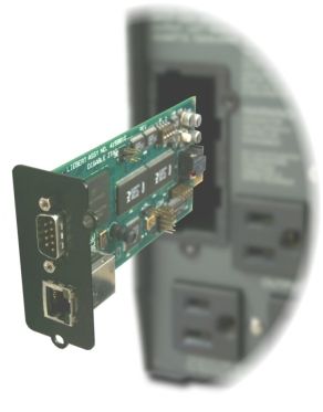
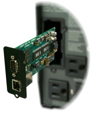
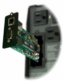
INSTALLATION
Installing the Card

The OpenComms Web Card is hot swappable and user-serviceable.
Although you do not need to turn off the UPS, disconnect any loads, or
restart the UPS to install or remove the card, discretion should be used.

CAUTION: The Intellislot Bay is located in close proximity to the UPS'
output and the UPS' electrical receptacles. Whenever possible, you
should turn the UPS OFF when installing the card.

To install the card:

1.Locate the Intellislot bay on the back of the UPS. For Nfinity, use the
Intellislot labeled "1".
2.Remove the plastic Intellislot cover and save the screws for Step 4.
3.Insert the OpenComms Web Card into the Intellislot bay.
4.Secure the card with the screws you removed in Step 2.

NOTE: The card is powered by the UPS during both normal and on bat-
tery operation. If the UPS is ON, the card will operate normally after a
brief boot up period.

Connecting the Card to the Network

To connect the card to the network, simply plug an Ethernet cable to the
RJ-45 connector on the card.

The card support 10Mbit and 100Mbit communication speeds at either
half or full duplex. The card ships from the factory in an auto-sensing
mode. In this mode, the card works to negotiate the optimal setting for
your network environment. To turn off the auto-sensing mode and force
the card's communication speed or duplex setting, you will need to open a
Service Terminal connection to the card. Please refer to the Service Ter-
minal section.

Configuring the Card
The card ships from the factory with DHCP service enabled. The MAC
address is located on a sticker affixed to the top of card. To give the card
a Static IP address, you will need to open a Service Terminal Connection
to the card. Refer to the Service Terminal section for more details.
Service Terminal
Opening a Service Terminal Connection

This section covers the Service Terminal in detail. From the Service Ter-
minal, you can configure all settings of the card.

NOTE: You can also configure many of the setting discussed in this sec-
tion from the Web. To specify that the card communicate at either 10Mbit
or 100Mbit instead of it trying to auto-negotiate, you must use the Service
Terminal

You access the Service Terminal by opening a direct serial connection to
the OpenComms Web Card.

1.Locate the blue serial configuration cable that shipped with the card.

NOTE: If you have misplaced the cable provided, you can use a standard
null modem cable with a DB-9F connector at both ends.

2.Connect one end of the blue serial configuration cable to the DB-9M
serial port on the OpenComms Web Card.

3.Connect the other end of the blue serial configuration cable to a termi-
nal or a PC running terminal emulator software, like HyperTerminal ™ or
ProComm ™.

4.Use the following communication settings:

BAUD RATE:9600
DATA BITS:8
PARITY:NONE
STOP BITS:1
FLOW CONTROL:NONE
5. Press "Enter" to see the Main Menu.

If you do not see the Main Menu, press "Enter" again several times. If the
Main Menu fails to appear, confirm that the blue configuration cable is
installed properly, that your PC or terminal COM port is active, and that
you are using the correct communication settings. If, after verifying the
cable and your communication settings are correct you still do not see the
Main Menu, reinstall the card in the Intellislot Bay.

NOTE: The card is powered by the UPS. If the UPS is ON, the card will
operate automatically. If you have the cable connected while inserting
the card, you will see initialization text scroll on your screen. If the card
has already been powered, you will not see this information.

Main Menu

From the Main Menu screen, you will find configuration information func-
tionally grouped.

Liebert Network Interface Card

Main Menu
----------
1: System Information
2: Network Interface
3: SNMP Communications
4: Web Server
5: Firmware Updates
6: Factory Settings

q: Quit and abort changes
x: Exit and save

Please select a key ?>

Changes you make using the Service Terminal will only take effect after
the card reboots.

Accordingly, always return to the Main Menu screen after making a
change or changes and then select either option "q" or "x". If you select
option "q" your changes will be aborted and the card will retain its previ-
ous settings. When you select option "x" the card will reboot and restart
with your changes.

Selecting Option "1" from the Main Menu opens the System Information
Menu.

Liebert Network Interface Card

System Information Menu
------------------------
1: Name              Data Room UPS
2: Contact          Network Services x100
3: Location          Building 2, Floor 4
4: Description Supporting Main Server

: Cancel menu level

Please select a key ?>

The System Information Menu contains four user-defined data fields. The
Service Terminal will report Uninitialized where you have not entered per-
sonalized data. The System Information Menu allows you to enter useful
location and contact information. The data in these fields is available via
SNMP and is presented in the support tab on the Web page.

A typical configuration includes:

Selecting option "1" to assign a name to the UPS.
Selecting option "2" to assign an administrative contact
Selecting option "3" to assign location information.
Selecting option "4" to assign a description.

The Name field can be up to 255 characters in length. The Contact,
Location, and Description fields can be up to 64 characters in length.

If you have made changes, you need to press "Esc" to return to the Main
Menu and then press "x" to exit and save changes.
Network Interface Menu

Selecting Option "2" from the Main Menu opens the Network Interface
Menu.

Network Interface Menu
-----------------------
1: Speed/Duplex Auto
2: Boot mode            DHCP
  IP Address            0.0.0.0
   Netmask              0.0.0.0

: Cancel menu level

Please select a key ?>

From the Network Interface Menu you can configure the Network setting
for the card

Select option "1" to change the communication speed of the card or the
duplex setting.

Please select a key ?> 1
Valid Selections:
------------------
1. Auto
2. 10Mbs/Half Duplex
3. 10Mbs/Full Duplex
4. 100Mbs/Half Duplex
5. 100Mbs/Full Duplex
Select Speed and Duplex Setting:

The Speed/Duplex default setting is Auto and the card attempts to negoti-
ate the optimal setting for your network environment. You can select a
fixed setting for either 10Mbit or 100Mbit speed, at either full or half
duplex.
Select option "2" to change Boot mode settings of the card.
Valid Selections:
------------------
1. Static
2. BootP
3. DHCP

Select Boot Mode:

Your Boot mode setting options are Static, BootP, and DHCP. The card
ships from the factory with DHCP service enabled. DHCP allows the card
to obtain an address dynamically from a DHCP server on your network.
The card also supports BootP dynamic configuration. If you are using
DHCP or BootP you may find want to configure your DHCP or BootP
server with the MAC Address of the card so that the server always
assigns the card a specific address. The MAC Address is printed on a
sticker affixed to the top of the card.

To assign the card a fixed IP address, you need to change the Boot mode
to STATIC and then provide an IP Address, Netmask, and Default Gate-
way.

Network Interface Menu
-----------------------
1: Speed/Duplex Auto
2: Boot mode            Static
3: IP Address           126.4.1.102
4: Netmask              255.255.255.0
5: Default Gateway 126.4.1.1

If you have made changes, you need to press "Esc" to return to the Main
Menu and then press "x" to exit and save changes.
SNMP Communication Menu

Liebert Network Interface Card

SNMP Communications Menu
-------------------------
1: Authentication Traps       'no'
2: Display/Modify Communities
3: Display/Modify Trap Communities

: Cancel menu level

Please select a key ?>

Selecting Option "3" from the Main Menu opens the SNMP Communica-
tions Menu.

From the SNMP Communications Menu you can configure the SNMP set-
ting and behavior of the card.

Select option "1" to turn authentication traps on or off. Enter "y" to enable
authentication traps. Enter "n" to disable authentication traps. (Authenti-
cation traps are desined to notify users of unauthorized SNMP access.)

Select option "2" to edit the list of devices you want to have access to the
card via SNMP.

Display/Modify Communities Menu
--------------------------------

1: 126.4.1.100       write MyCommunity

: Cancel menu level
dd elete dit

Complex lines allowed. e.g.
 ?>
The options "a" "d" and "e" allow you to manage your list of network
devices with access to the card. These options can be used as a com-
plex instruction to add a single device, specify read/write access rights,
and designate the Community String. For, example, entering:

"a 126.4.1.200 read NewCommunity"

adds device 126.4.1.200 to the community list. The menu will update:

Display/Modify Communities Menu
--------------------------------

1: 126.4.1.100      write MyCommunity
2: 126.4.1.200      read NewCommunity

: Cancel menu level
dd elete dit

As you are adding communities, you need to consider access rights.
Notice above, that 126.4.1.100 has write access when the device passes
the correct Community String of MyCommunity. This means that this net-
work device has both read and write access to the card, whereas
126.4.1.200 has only the ability to read information when providing the
correct Community String. Devices with write access can control the UPS
and reconfigure settings of the card.

Select option "3" to edit the list of devices you want to receive traps from
the card via SNMP.

Display/Modify Trap Communities Menu
-------------------------------------

1: 126.4.1.100          MyCommunity

: Cancel menu level
dd elete dit

Complex lines allowed. e.g.
 ?>
The options "a" "d" and "e" allow you to manage you list of network
devices that will receive SNMP Traps from the card. These options can
be used as a complex instruction to add a single device and designate the
Community String. For, example, entering:

"a 126.4.1.200 NewCommunity"

adds device 126.4.1.200 to the trap community list. The menu will update:

Display/Modify Trap Communities Menu
-------------------------------------

1: 126.4.1.100         MyCommunity
2: 126.4.1.200         NewCommunity

: Cancel menu level
dd elete dit

It is important to remember that you will often need to add a network
device to both the Communities Menu and the Trap Communities Menu
for your SNMP implementation to work as designed.

MultiLink ™ Software

The OpenComms Web Card works with MultiLink software to provide
unattended graceful operating systems shutdown. The card can be mon-
itored by MultiLink over the network, eliminating the need for serial
cables. Downloadable versions of MultiLink and information about install-
ing and configuring MultiLink software is available online at www.lie-
bert.com.

Please see Appendix A for more on MultiLink.
Web Server Menu

Web Server Menu
----------------
1: Web Server 'enabled'
2: Change Username/Password

: Cancel menu level

Please select a key ?>

Selecting Option "4" from the Main Menu opens the Web Server Menu.

From the Web Server Menu you can enable/disable the Web functionality
of the card and edit the Username/Password, which regulates access to
the Web control and configuration tabs.

Select option "1" to turn the entire Web Server ON or OFF.

NOTE: If you select disabled, the card will be totally inaccessible from the
Web, although it will continue to operate as an SNMP-only agent.

Select option "2" to edit the Username or Password that must both be
entered correctly to control the UPS or to change configuration settings of
the card from the Web.

The factory default User Name is Liebert and the Password is Liebert.
Because this is a well-known username and password, you should
change it as soon as possible. You can also change the Username or
Password from the Web.

From the service terminal, you do not need to know the current Username
of Password to make a change.

NOTE: When changing the Username or Password from the Service Ter-
minal, it is possible to leave either field blank. However, blank fields are
not recommended. Entering a blank User Name will result in the user
name being equal to the last known name. Entering a blank for the pas-
sord will result in a blank password.

If you have made changes, you need to press "Esc" to return to the Main
Menu and then press "x" to exit and save changes.
Firmware Updates Menu

Firmware Updates Menu
----------------------
1: Initiate XMODEM session...

: Cancel menu level

Please select a key ?>

Selecting Option "5" from the Main Menu opens the Firmware Updates
Menu.

From the Firmware Updates Menu you can reload the firmware of the
card. Please consult the instructions you downloaded or received with
you new firmware version.
Factory Settings Menu

Factory Settings Menu
----------------------
1: Reset to Factory Defaults

 Manufacture Date      OCT 27,2000
 MAC Address       00-00-68-16-00-03
 Serial Number 415981G101D2000OCT270003

: Cancel menu level

Please select a key ?>

Selecting Option "6" from the Main Menu opens Factory Settings Menu.

The Factory Settings Menu displays information you may be asked by
Liebert Technical Applications Support and is the only electronic place
you can access the MAC address on demand. From the menu, you also
have the option of resetting all the settings of the card the factory default.
Selecting "1" will likely cause the card to be inaccessible from the network
so its use should be applied with caution.

If you have made changes, you need to press "Esc" to return to the Main
Menu and then press "x" to exit and save changes.
Web
Opening a Web Connection
This section explains the Web interface in detail. From the Web, you can
monitor and control the UPS in which the card is installed. You can also
configure many settings of the card.

NOTE: To specify that the card communicates at either 10Mbit or
100Mbit, instead of it trying to auto-negotiate, you must use the Service
Terminal.

You access the Web Interface of the OpenComms Web Card by opening
a direct web browser. The card utilizes functionality of Microsoft Internet
Explorer 5.0 or higher. Whenever possible, you should use the latest
copy of IE.

1. Open your web browser software.
2. Enter the IP address or hostname of the card in the address line of
   your browser.

The first page you will see every time you open a new Web connection to
the card is the Power Flow folder in the monitor tab. After your browser
connects, you will see a screen very similar to below:
You will notice that information on the Web page is grouped in Tabs and
Folders. The card organizes similar information together in folders, and
similar functions in tabs.

Tabs: Across the top of the screen are four tabs, monitor, control, config-
ure, and support. As the tab names suggest, different information is pre-
sented and different operations are available to you under each tab.

Folders: Within each tab, you will see a different list of folders on the left
pane of your screen. Here, display, control, and configuration information
grouped logically. If, for example you click the Input folder under the
monitor tab, you will see only information about the UPS' input power.

A rigorous explanation of the information in the tabs and folders is not
necessary, as you will quickly sort out why things are where they are. So,
the discussion that will follow for the rest of the Web section touches on
the important functionality delivered in certain areas.
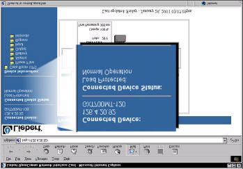
Connected Device Information
Clicking between the monitor, contol, configure, and support tabs gives
you access to folder lists on the bottom of the left pane. Although the
folder list changes, depending on the tab selected, the top portion of the
left pane remains constant. In the top or the left pane, connected device
information and connected UPS status is always presented.

The IP address of the card and the Liebert UPS model type is presented
under Connected Device:. In this example, the InOpenComms Web Card
is installed in a UPStation GXT 700VA UPS and has been assigned the
IP address, 126.4.20.92.

The current operating state of the UPS is presented under Connected
Device Status: along with the most serious UPS alarm, if one if present.
For our example above, the UPS is operating normally with the load pro-
tected.
Security
By opening a connection to the OpenComms Web Card, you are able to
do three things. You can Monitor, Configure and Control the UPS.

The card allows any user with access to the network segment on which it
resides to monitor the UPS. This means anyone on the segment can
view the entire contents of the monitor and support tabs.

The card restricts access to the folders in the control and configure tabs.
When a user clicks on a folder, they are prompted for a User Name and
Password.

The factory default User Name is "Liebert" and the Password is "Liebert".
Because this is a well-known username and password, you should
change it as soon as possible. You should change the username and
password as soon as possible. If you have not made this change from
the Service Terminal, you can do so from the Web.
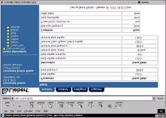
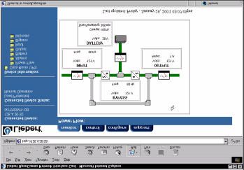
Monitor Tab
When you select the monitor tab, you are presented with Connected
Device: and Connected Device Status: on the top of the left pane. The
Folder list is at the bottom of the pane under Device Information:.

The first page you will see every time you open a new Web connection to
the card is the Power Flow folder in the monitor tab. After your browser
connects, you will see a screen very similar to below:

From the monitor Tab, you are able to view the parametric data of the
UPS.

The Power Flow folder provides a graphical representation of the current
state of the UPS along with useful information about Input, Output, and
Battery voltages as well as Battery runtime information.

The Alarm folder provides a list or any present UPS alarms.
Clicking on the Battery, Output, Input, Bypass (not supported in Power-
Sure Interactive UPSs), or Internals folder replaces the summary data
presented on the graphical power flow pane with a tabular view of the
complete list of data points reported by the UPS. Clicking on the Input
folder presents a screen similar to:

In the tabular view data, like Input voltage, that changes over time is
grouped as a Parameter. Values, which are known to the UPS, like Nom-
inal input frequency, are reported in Information. Finally, condition
parameters, like Utility failed, are together in a table labeled, Condition.
The list of data in each of these sections and folders varies across UPS
product lines and sizes and will change depending on the UPS in which
you have installed the card.
Control Tab
When you select the control tab, you are presented with Connected
Device: and Connected Device Status: on the top of the left pane. The
Folder list is at the bottom of the pane under Control Operations:.

As detailed in the Web Security section, a Username and Password pro-
tect the folders in the control tab.

From the control tab you can silense alarms remotely, turn the UPS' out-
put ON or OFF or Reboot the UPS.
Each folder represents a different control behavior and this list will vary
across UPS product lines and sizes.
Configure Tab
When you select the configure tab, you are presented with Connected
Device: and Connected Device Status: on the top of the left pane. The
Folder list is at the bottom of the pane under Configuration Categories:.

As detailed in the Web Security section, a Username and Password pro-
tect the folders in the configure tab.

When you click on a folder under Configuration Categories: you will be
able to edit network and device settings, including SNMP community lists.
The folder list is shown below:

Device Info
Clicking on the Device Info folder allows you to edit the Name, Contact,
Location, and Description fields.

Factory Defaults
Clicking on the Factory Defaults folder allows you to reset the card to the
factory settings.

Network
Clicking on the Network folder allows you to reset the card to the factory
settings.
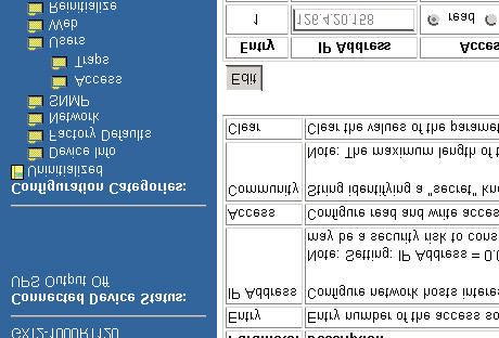
SNMP
Clicking on the SNMP folder allows you to enable authentication traps.

Clicking on the Access or Traps folder allows you to configure the devices
you want to have access to the card via SNMP and devices you want to
receive traps from the card. The Access folder is shown below:

As you are adding communities, you need to consider access rights.
Notice above, that 126.4.1.100 has write access when the device passes
the correct Community String of MyCommunity. This means that this net-
work device has both read and write access to the card, whereas
126.4.1.200 has only the ability to read information when providing the
correct Community String. Devices with write access can control the UPS
and reconfigure settings of the card. In order for a device you have added
to the Access folder to also receive notification from the card via SNMP
Traps for UPS alarms and condition changed, you also need to add the
device toe the Traps folder.

Users
Clicking on the Users folder allows you to edit the Username or Password
that must both be entered correctly to control the UPS or change configu-
ration settings of the card from the Web.

The factory default User Name is Liebert and the Password is Liebert.
Because this is a well-known username and password, you should
change it as soon as possible. You can also change the Username or
Password from the Web.

From the Web, you need to know the current Username of Password to
make a change.

Web
Clicking on the Web folder allows you to modify the Web browser refresh
rate. Due to the static nature of the Web, the card instructs your Web
browser to refresh many areas of the card's web page at a specific inter-
val.
Configure Tab - Making and Saving Configurations
Similar to configuring the card using the Service Terminal, every time you
make a configuration change, the card will have “save and reboot” for that
change to take effect. As you navigate between the card's control web
pages, you will notice that configuration screens include Edit and Save
buttons and a Reinitialization folder. As an example, the screen shot
below shows the edit fields available under the configure tab when you
select the SNMP folder:

The Edit button allows configuration and parameter changes.

Once the Edit button is selected, a Save button will appear in its place.
The Save button can be used at any time during the (re)configuration pro-
cess. Once the Save button is selected, the user will be prompted to rein-
itialize the card, so
that the new set-
tings      will   take
effect. During this
time, the card is
unavailable on the
network. When this
process         begins,
your web browser
may be instructed
to open a new page.
Configure Tab - After Reinitialization
Once card reinitialization is selected and confirmed, the card is unavail-
able on the network. As the card reboots, it first begins communicating
on the network and it will begin communicating with the UPS in which it is
installed. The card will present to you some helpful information during the
period of time that it is restarting.
Support Tab
When you select the support tab, you are presented with Connected
Device: and Connected Device Status: on the top of the left pane. A sin-
gle device list is at the bottom of the pane under Support:.

The support tab displays the Name, Location, and Description fields as
well as relevant contact information for Liebert Technical Applications
support.
SNMP
The OpenComms Web Card utilizes a SNMPv1 agent and is MIB-II com-
pliant. The card supports the open standard UPS MIB RFC1628, with
additional functionality and support through the Liebert Global Products
MIB. A copy of the Liebert Global Products MIB is included on the CD
included with your purchase. Likewise, the latest version of Libert Global
Products MIB can be obtained at www.liebert.com.
Appendices
MultiLink Support

The most frequently asked question about configuring MultiLink to moni-
tor a SNMP device, like the OpenComms Web Card, across the network
is, what community string do I use?

NOTE: Use the community string LiebertEM for MultiLink.

Configuring for MultiLink support from the Service Terminal

From the Main Menu, select option "3" for SNMP Communications Menu.
In order for MultiLink to monitor the card, the network address information
of the machine on which MultiLink is installed needs to be added to both
the Display/Modify Communities and the Display/Modify Trap Communi-
ties.

As an example, you have installed MultiLink on a PC and you will monitor,
across the network, the OpenComms Web Card you are now installing.
Your PC has the IP address of 126.4.1.1.

Select option "2" from the SNMP Communications Menu and add
126.4.1.1 with the community string Liebert EM.
Select option "3" from the SNMP Communications Menu and add
126.4.1.1 with the community string Liebert EM.

If you have made changes, you need to press "ESC" to return to the Main
Menu and then press "x" to exit and save changes.

Adding to both the Communities list and the Trap Communities list is nec-
essary for MultiLink to work properly.

Configuring for MultiLink support from the Web

Open a web connection to the OpenComms Web Card. Click on the Con-
figure tab. In order for MultiLink to monitor the card, the network address
information of the machine on which MultiLink is installed needs to be
added to both the Access and Traps selection folders as stated in the
above examples.
SL-52610 (9/02) Rev.2
You can also read