SONICOS 7 ACCESS POINTS - ADMINISTRATION GUIDE - SONICWALL
←
→
Page content transcription
If your browser does not render page correctly, please read the page content below
SonicOS 7

Access Points
Administration Guide

Contents

Settings                                                                                                 5
Synchronize Access Points                                                                                6
Provisioning Overview                                                                                    6
Creating/Modifying Provisioning Profiles                                                                  7
    Adding/Editing a Provisioning Profile - Getting Started                                               8
    General Settings for Provisioning Profiles                                                            9
    5GHz/2.4GHz Radio Basic Settings for Provisioning Profiles                                           10
    5GHz/2.4GHz Radio Advanced Settings for Provisioning Profiles                                        21
    Sensor Settings for WIDP in Provisioning Profiles                                                    27
    Mesh Network Settings for Provisioning Profiles                                                      28
    3G/4G/LTE WWAN Settings for Provisioning Profiles                                                    30
    Bluetooth LE Settings for Provisioning Profiles                                                      31
    Deleting Access Point Profiles                                                                       32
    Product Specific Configuration Notes                                                                 33
Managing Access Points                                                                                   33
   Deleting Access Point Objects                                                                         34
   Rebooting Access Point Objects                                                                        34
   Modifying Access Point Objects                                                                        34

Firmware Management                                                                                      35
About Firmware Management                                                                                35
Obtaining the Latest SonicWall Firmware                                                                  36
Downloading Firmware from a Specific URL                                                                 37
Uploading Firmware to an Access Point                                                                    37

Floor Plan View                                                                                          39
Managing the Floor Plans                                                                                 40
   Selecting a Floor Plan                                                                                40
   Creating a Floor Plan                                                                                 40
   Editing a Floor Plan                                                                                  40
   Set Measuring Scale                                                                                   41
Managing Access Points                                                                                   41
   Available Devices                                                                                     42
   Added Access Points                                                                                   42
   Removing Access Points                                                                                42
   Export Image                                                                                          42
   Context Menu                                                                                          42

                                                          SonicOS 7 Access Points Administration Guide        2
                                                                                             Contents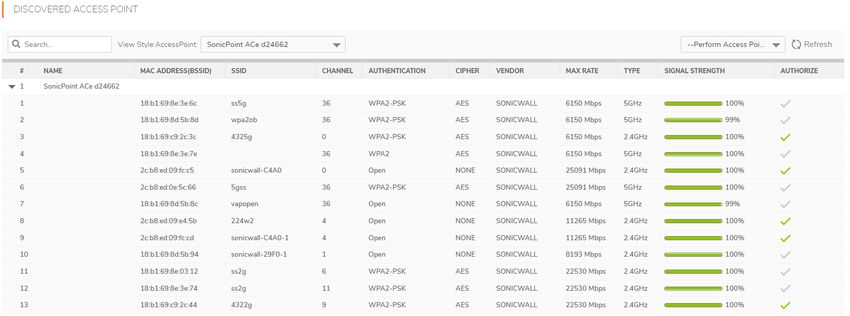
Station Status                                                                                       44

Intrusion Detection Services                                                                         45
Scanning Access Points                                                                               46
Authorizing Access Points                                                                            47

Advanced IDP                                                                                         48
Enabling Wireless IDP on a Profile                                                                   48
Configuring Wireless IDP Settings                                                                    49
Viewing KRACK Sniffer Packets                                                                        50

Packet Capture                                                                                       52

Virtual Access Points                                                                                53
Before Configuring VAPs                                                                              55
    Determining Your VAP Needs                                                                       55
    Determining Security Configurations                                                              55
    Sample Network Definitions                                                                       56
    Prerequisites                                                                                    56
    VAP Configuration Worksheet                                                                      57
Access Point VAP Configuration Task List                                                             58
Virtual Access Point Profiles                                                                        59
     Virtual Access Point Schedule Settings                                                          59
     Virtual Access Point Profile Settings                                                           60
     ACL Enforcement                                                                                 61
     Remote MAC Address Access Control Settings                                                      62
Virtual Access Points                                                                                62
     General Tab                                                                                     63
     Advanced Tab                                                                                    63
Virtual Access Point Groups                                                                          64

RF Monitoring                                                                                        65
Prerequisites                                                                                        66
RF Monitoring Summary                                                                                66
802.11 General Frame Setting                                                                         67
802.11 Management Frame Setting                                                                      67
802.11 Data Frame Setting                                                                            68
Discovered RF Threat Stations                                                                        69
Adding a Threat Station to the Watch List                                                            70
Practical RF Monitoring Field Applications                                                           71
    Using Sensor ID to Determine RF Threat Location                                                  71
    Using RSSI to Determine RF Threat Proximity                                                      72

RF Analysis                                                                                          74
Choosing RF Analysis                                                                                 74
The RF Environment                                                                                   74

                                                      SonicOS 7 Access Points Administration Guide        3
                                                                                         Contents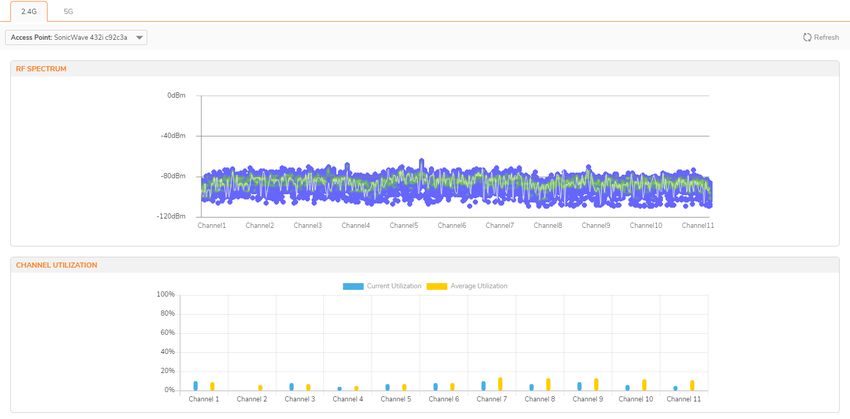
Using RF Analysis on SonicWall Access Points                                                       75
    Understanding the RF Score                                                                     75
    Channel Utilization Graphs and Information                                                     76
    Viewing Overloaded Channels                                                                    77
    RFA Highly Interfered Channels                                                                 77

RF Spectrum                                                                                        79

FairNet                                                                                            81
Supported Platforms                                                                                82
FairNet Features                                                                                   82
Management Interface Overview                                                                      82
Configuring FairNet                                                                                83

Wi-Fi Multimedia                                                                                   84
WMM Access Categories                                                                              84
Assigning Traffic to Access Categories                                                             86
    Specifying Firewall Services and Access Rules                                                  86
    VLAN Tagging                                                                                   86
Configuring Wi-Fi Multimedia Parameters                                                            87
   Configuring WMM                                                                                 87
   Creating a WMM Profile for an Access Point                                                      88

3G/4G/LTE WWAN                                                                                     89

Bluetooth LE Devices                                                                               90
Viewing BLE Scanned Data                                                                           90

Radio Resource Management                                                                          92
Configuring Radio Resource Management                                                              92
Configuring Dynamic Channel Selection                                                              94

SonicWall Support                                                                                  96
About This Document                                                                                97

                                                    SonicOS 7 Access Points Administration Guide        4
                                                                                       Contents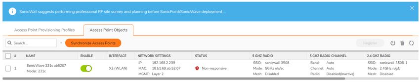
1

                                                                                          Settings
The most effective way to provision wireless access points is let the SonicOS firewall automatically detect
the access points and use one of the default profiles. SonicOS includes four default profiles, one for each
generation of SonicWall access points: SonicPointN, SonicPointNDR, SonicPointACe/ACi/N2, and
SonicWave. These can be used as is, or they can be customized to suit your configuration. You can also
build new profiles based on the type of SonicWall access point you have.

The Device > Access Points > Settings page displays informational messages and shows the firmware
version for operational access points.

The access point profiles are displayed in the Access Point Provisioning Profiles tab. You can edit each
profile or add a new profile.

The Access Point Objects tab displays the settings for connected access points, and provides Edit icons to
edit them or perform other actions.

    NOTE: When wireless LAN is disabled, all Access Points and Wireless related pages disappear.
    Wireless Zone is removed from zone type. And any existing WLAN zones or objects are not editable
    anymore.

Topics:
    l   Synchronize Access Points
    l   Provisioning Overview
    l   Creating/Modifying Provisioning Profiles
    l   Managing Access Points

                                                                   SonicOS 7 Access Points Administration Guide        5
                                                                                                        Settings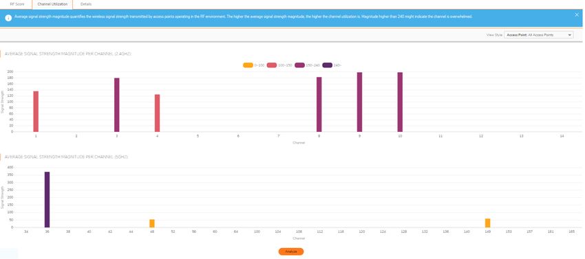
Synchronize Access Points
Click Synchronize Access Points at the top of the Device > Access Points > Settings page to issue a
query from the SonicWall appliance to the WLAN Zone. All connected access points report their current
settings and statistics to the appliance. SonicOS also attempts to locate the presence of any newly
connected access points that are not yet registered with the firewall.

    NOTE: The button polls the access points, but does not push configuration to them.

Provisioning Overview
SonicPoint/SonicWave Provisioning Profiles provide a scalable and highly automated method of configuring
and provisioning multiple access points across a Distributed Wireless Architecture. SonicPoint/SonicWave
Profile definitions include all of the settings that can be configured on a SonicWall access point, such as
radio settings for the 2.4GHz and 5GHz radios, SSID’s, and channels of operation.

After you have defined a access point profile, you can apply it to a Wireless zone. Each Wireless zone can be
configured with one access point profile. Any profile can apply to any number of zones. Then when an
access point is connected to a zone, it is automatically provisioned with the profile assigned to that zone.

When an access point is first connected and powered up, it has a factory default configuration (IP address:
192.168.1.20, username: admin, password: password). Upon initializing, the unit attempts to find a
SonicOS device with which to peer. When a SonicOS device starts up, it also searches for access points
through the SonicWall Discovery Protocol. If the access point and a peer SonicOS device find each other,
they communicate through an encrypted exchange where the profile assigned to the relevant Wireless zone
is used to automatically provision the newly added access point unit.

As part of the provisioning process, SonicOS assigns the discovered access point a unique name and
records its MAC address, the interface, and zone on which it was discovered. If part of the profile, it can also
automatically assign an IP address so that the access point can communicate with an authentication server
for WPA-EAP support. SonicOS then uses the profile associated with the relevant zone to configure the
2.4GHz and 5GHz radio settings.

Note that changes to profiles do not affect units that have already been provisioned and are in an
operational state. Configuration changes to operational access points can occur in two ways:

    l   Through manual configuration changes
        This option is the best choice when a single, or a small set of changes are to be made, particularly
        when that individual access point requires settings that are different from the profile assigned to its
        zone.
    l   Through un-provisioning
        Deleting an access point effectively un-provisions the unit. It clears its configuration and places it into
        a state where it automatically engages the provisioning process anew with its peer SonicOS device.
        This technique is useful when the profile for a zone is updated or changed, and the change is set for
        propagation. It can be used to update firmware on access points, or to simply and automatically
        update multiple access points in a controlled fashion, rather than changing all peered access points
        at the same time, causing service disruptions.

                                                                      SonicOS 7 Access Points Administration Guide    6
                                                                                                           Settings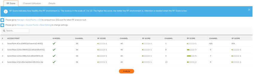
Creating/Modifying Provisioning Profiles
On the Device > Access Points > Settings page, you can configure and manage the provisioning profiles
as well as the individual objects. You can add any number of profiles.

    NOTE: SonicPoint AC refers to SonicPoint ACe/ACi/N2; SonicPoint refers to all SonicPoint devices.
    SonicWave refers to SonicWave 432e/432i/432o/224w/231c/231o. SonicPoint ACs are supported on
    appliances running SonicOS 6.2.2 and newer, while SonicWave devices are supported on SonicOS 6.5
    and newer.

Navigate to Device > Access Points > Settings page. The four default SonicOS profiles are listed along
with any custom profiles you’ve developed under the SonicPoint/SonicWave Provisioning Profiles
section. To modify any of the default provisioning profiles, hover on the profile and click the Edit icon, and
make the appropriate changes.

    IMPORTANT: Because creating or modifying the SonicPoint/SonicWave Provisioning Profiles are very
    similar across all access point types, this section reviews how to add a new profile for a SonicWave
    device. Significant differences in the general process are noted and described in more detail later in this
    section.

    NOTE: The SonicWall-provided provisioning profiles cannot be deleted so the corresponding Delete
    icon is grayed out and not active.

The Add New Profile option has several screens where similar settings are grouped. The procedures are
grouped to match those screens.

Topics:
    l   Adding/Editing a Provisioning Profile - Getting Started
    l   General Settings for Provisioning Profiles
    l   5GHz/2.4GHz Radio Basic Settings for Provisioning Profiles
    l   5GHz/2.4GHz Radio Advanced Settings for Provisioning Profiles
    l   Sensor Settings for WIDP in Provisioning Profiles
    l   Mesh Network Settings for Provisioning Profiles
    l   Bluetooth LE Settings for Provisioning Profiles
    l   Deleting Access Point Profiles
    l   Product Specific Configuration Notes

                                                                    SonicOS 7 Access Points Administration Guide    7
                                                                                                         Settings
Adding/Editing a Provisioning Profile - Getting
Started
To add a new provisioning profile:
   1. Navigate to Device > Access Points > Settings > Access Point Provisioning Profiles page.
   2. In the Add New Profile drop-down, select the type of profile you want to build. For an example,
      SonicWave Profile was selected.
          NOTE: To modify an existing profile, click on the Edit icon for profile you want to update.

                                                                 SonicOS 7 Access Points Administration Guide    8
                                                                                                      Settings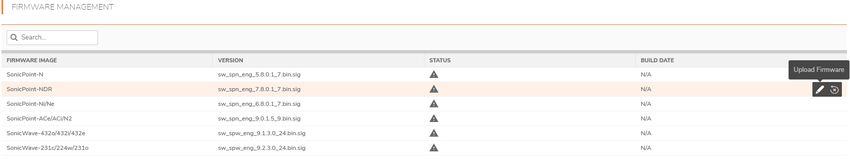
General Settings for Provisioning Profiles
To configure the options on the General screen:
   1. Set the SonicWave Settings.

       Option                     Action
       Enable                     When selected, enables the SonicWave access point. By default,
                                  this option is enabled.
       Retain Settings            When selected, retains the customized until the next time the unit
                                  is rebooted. Edit option is enabled and the Retain Settings dialog
                                  is displayed. You can customize which settings needs to be
                                  retained.
       Enable RF Monitoring       When selected, enables wireless RF-threat, real-time monitoring
                                  and management.
       Enable LED                 When selected, turns on the SonicWave LEDs. If left unchecked,
                                  which is the default, the LEDs stay off.
       Enable Low Power Mode When selected, allows the SonicWave to operate in a low power
                             mode because of the power source not being standard 802.3at
                             PoE.
       Name Prefix                Type the prefix used for the name in the field provided.
       Country Code               From the drop-down menu, select the country code for the
                                  country in which the access point is deployed.
       EAPOL Version              Select EAPoL version from the drop-down menu. Note that V2
                                  provides the better security.
       Band Steering Mode         Select the band steering mode from the drop-down menu.
                                  Options include: Disable, Auto, Prefer 5GHz, or Force 5GHz.
   2. Set the Virtual Access Point Settings:
         a. For 5GHz Radio Virtual AP Group, select a Virtual Access Point object group from the drop-
            down menu.
         b. For 2.4GHz Radio Virtual AP Group, select a Virtual Access Point object group from the
            drop-down menu.

                                                               SonicOS 7 Access Points Administration Guide    9
                                                                                                    Settings
3. Scroll down to see the other General Settings.
4. Set the Dynamic VLAN ID Assignment.
To enable the options under Dynamic VLAN ID Assignment, you need create a WLAN zone under
Object > Match Objects > Zones and VLAN interface under Network > System > VLAN
Translation.
5. Configure the SSLVPN Tunnel Settings:
a. Type in the SSLVPN Server name or IP address in the field provided.
b. Type the User Name for the SSLVPN server in the field provided.
c. Type the Password to authenticate on the SSLVPN server.
d. Type the Domain name in the field provided.
e. Select the Auto-Reconnect option to enable it.
f. If you want to configure Layer 3 SSLVPN, click SSL VPN > Client Settings and define the
appropriate settings.
6. Set the Administrator Settings:
a. Type in the user Name of the network administrator.
b. Type in the Password for the network administrator.
5GHz/2.4GHz Radio Basic Settings for Provisioning
Profiles
The basic settings for 5GHz Radio and 2.4GHz Radio across the different types of access points are similar
and have only a few differences. These differences are noted in the steps.If a VAP group was selected in the
General settings, however, a different options display.
The following topics describe settings on the 5GHz/2.4GHz Radio Basic screens:
SonicOS 7 Access Points Administration Guide 10
SettingsTopics:
l Radio Settings
l Wireless Security
l Protected Management Frames (PMF Option)
l About Local Radius Servers and EAP Authentication Balancing
l Configuring Radius Server Settings
l ACL Enforcement
l Remote MAC Address Access Control Settings
Radio Settings
To configure 5GHz Radio/2.4GHz Radio Basic Settings:
1. Click on 5GHz Radio Basic or 2.4GHz Radio Basic.
2. Select Enable Radio to enable the radio bands automatically on all access points provisioned with
this profile. This option is selected by default.
3. From the Enable Radio drop-down menu, select a schedule for when the radio is on or create a new
schedule. The default is Always On.
4. Select your preferred radio mode from the Mode drop-down menu:
RADIO MODE CHOICES
5GHz Radio Basic 2.4GHz Radio Basic Definition
5GHz 802.11n Only 2.4GHz 802.11n Only Allows only 802.11n clients access to your
wireless network. 802.11a/b/g clients are
unable to connect under this restricted
radio mode.
5GHz 802.11n/a Mixed 2.4GHz 802.11n/g/b Mixed Supports 802.11a and 802.11n (5GHz
(SonicPoint AC/NDR Radio) or 802.11b, 802.11g, and 802.11n
default) (2.4GHz Radio) clients simultaneously. If
your wireless network comprises multiple
types of clients, select this mode.
5GHz 802.11a Only Select this mode if only 802.11a clients
(SonicPoint NDR access your wireless network.
default)
SonicOS 7 Access Points Administration Guide 11
Settings2.4GHz 802.11g Only If your wireless network consists only of
802.11g clients, you might select this
mode for increased 802.11g performance.
You might also select this mode if you wish
to prevent 802.11b clients from
associating.
5GHz 802.11ac/n/a Supports 802.11ac, 802.11a, and 802.11n
Mixed (SonicWave and clients simultaneously. If your wireless
SonicPoint AC default) network comprises multiple types of
clients, select this mode.
5GHz 802.11ac Only Allows only 802.11ac clients access to your
wireless network. Other clients are unable
to connect under this restricted radio
mode.
TIP: For 802.11n clients only: If you want optimal throughput, SonicWall recommends the
802.11n Only radio mode. Use the 802.11n/b/g Mixed radio mode for multiple wireless client
authentication compatibility.
For optimal throughput for 802.11ac clients, SonicWall recommends the 802.11ac Only radio
mode. Use the 802.11ac/n/a Mixed radio mode for multiple wireless client authentication
compatibility.
NOTE: The available 802.11n 5GHz/2.4GHz Radio Settings options change depending on the
mode selected. If the wireless radio is configured for a mode that:
l Supports 802.11n, the following options are displayed: Radio Band, Primary Channel,
Secondary Channel, Enable Short Guard Interval, and Enable Aggregation.
l Does not support 802.11n, only the Channel option is displayed.
5. In the SSID field, enter a recognizable string for the SSID of each access point using this profile. This
is the name that appears in clients’ lists of available wireless connections.
TIP: If all SonicPoints or SonicWaves in your organization share the same SSID, it is easier for
users to maintain their wireless connection when roaming from one access point to another.
6. Select a radio band from the Radio Band drop-down menu:
NOTE: When Mode = 5GHz 802.11a Only, the Radio Band option is not available.
l Auto - Allows the appliance to automatically detect and set the optimal channel for wireless
operation based on signal strength and integrity. If selected for one, both the Primary
Channel and Secondary Channel should set to Auto. This is the default setting.
l Standard - 20MHz Channel—Specifies that the radio uses only the standard 20MHz
channel.
l Wide - 40MHz Channel—Available when any mode except 5GHz 802.11a Only is selected
for the Radio Band. It specifies that the radio uses only the wide 40MHz channel.
l Wide - 80MHz Channel—Available only when 5GHz 802.11ac/n/a Mixed or 5GHz
802.11ac only is selected for the Radio Band, specifies that the 5GHz Radio uses only the
wide 80MHz channel. (Not available when the Mode is 5GHz 802.11n Only, 5GHz
802.11n/a Mixed, or 5GHz 802.11a Only.)
SonicOS 7 Access Points Administration Guide 12
Settings7. Select the channel or channels based on the Mode and Radio Band options chosen:
Mode Radio Band Channel
5GHz 802.11n Only Auto The Primary Channel and Secondary
Channel fields default to Auto.
Standard - 20 MHz Select Auto or one of the radio channels
Channel specified in the Standard Channel drop-
down menu.
Wide - 40 MHz Channel Select Auto or one of the radio channels in
the Primary Channel. The Secondary
Channel is automatically defined as Auto.
5GHz 802.11n/a Auto The Primary Channel and Secondary
Mixed Channel fields default to Auto.
Standard - 20 MHz Select Auto or one of the radio channels
Channel specified in the Standard Channel drop-
down menu.
Wide - 40 MHz Channel Select Auto or one of the radio channels in
the Primary Channel. The Secondary
Channel is automatically defined as Auto.
5GHz 802.11a Only (no option) Select Auto or one of the radio channels
specified in the Channel drop-down menu.
5GHz 802.11ac/n/a Auto The Channel field defaults to Auto.
Mixed Standard - 20 MHz Select Auto or one of the radio channels
Channel specified in the Channel drop-down menu.
Wide - 40 MHz Channel Select Auto or one of the radio channels in
the Channel drop-down menu.
Wide - 80 MHz Channel Select Auto or one of the radio channels in
the Channel drop-down menu.
5GHz 802.11ac Only Auto The Channel field defaults to Auto.
Standard - 20 MHz Select Auto or one of the radio channels
Channel specified in the Channel drop-down menu.
Wide - 40 MHz Channel Select Auto or one of the radio channels in
the Channel drop-down menu.
Wide - 80 MHz Channel Select Auto or one of the radio channels in
the Channel drop-down menu.
8. Select Enable Short Guard Interval to enable it. This allows you to increase the radio data rate by
shortening the guard interval. Be sure the wireless client can support this to avoid compatibility
issues.
9. Select Enable Aggregation to enable it. This allows you to increase the radio throughput by sending
multiple data frames in a single transmission. Be sure the wireless client can support this to avoid
compatibility issues.
SonicOS 7 Access Points Administration Guide 13
SettingsWireless Security
NOTE: The SonicOS interface is context-sensitive. If a VAP Group was selected in the General screen,
the Wireless Security section is hidden and you can skip this section.
To set the Wireless Security options:
1. Scroll down to the Wireless Security section. The options vary depending on the selected
Authentication Type.
SonicOS 7 Access Points Administration Guide 14
SettingsTo configure Wireless Security:
1. In the Wireless Security section, select the Authentication Type from the drop-down menu.
NOTE: The options available change with the type of configuration you select. If a WPA2 - EAP
option is selected, the Radius Server Settings section is displayed.
2. Define the remaining settings, using the following tables as a reference:
WEP SETTINGS FOR WIRELESS SECURITY
WEP Description
Authentication Type WEP Key Mode Settings
WEP (Wired Equivalent Privacy) is standard for Wi-Fi wireless network security. Open system
uses and exchange of information to authenticate and then encrypts the data. Shared keys
uses a shared secret key to authenticate.
WEP - Both (Open WEP Key Mode = None Remaining settings are grayed out and
System & Shared Key) cannot be selected.
WEP Key Mode = 64 bit, l In Default Key field, select the
128 bit or 152 bit. default key (the key that is tried
The number of bits indicates first). Key 1 is the default.
the key strength of the WEP l In the Key Entry field, choose
key. whether the key is Alphanumeric
or Hexadecimal (0-9, A-F).
l In the fields for Key 1, Key 2, Key 3,
and Key 4 enter encryption keys that
are used when transferring data.
WEP - Open System Remaining settings are grayed out and
cannot be selected.
WEP - Shared Key WEP Key Mode = 64 bit, l In Default Key field, select the
128 bit or 152 bit. default key (the key that is tried
The default is 152 bit. first). Key 1 is the default.
l In the Key Entry field, choose
whether the key is Alphanumeric
or Hexadecimal (0-9, A-F). The
Hexadecimal option is the default.
l In the fields for Key 1, Key 2, Key 3,
and Key 4 enter encryption keys that
are used when transferring data.
WPA2 SETTINGS FOR WIRELESS SECURITY
Description
Authentication Type Settings
WPA and WPA2 (Wi-Fi Protected Access) are newer protocols for protecting wireless devices.
Selecting one of the WPA2 - AUTO options allows the WPA protocol to be used if a device is
not enabled for WPA2.
WPA2 - PSK l Select Cipher Type from the drop-down menu.
Options are AES (default), TKIP, or Auto.
SonicOS 7 Access Points Administration Guide 15
SettingsDescription
Authentication Type Settings
l Set the Group Key Interval in seconds. The
default is 86400.
l For SonicWave, select the PMF Option from the
drop-down menu. See Protected Management
Frames (PMF Option).
l Define the Passphrase for the public shared key.
WPA2 - EAP l For SonicWave, select the Authentication
Balance Method from the drop-down menu. See
About Local Radius Servers and EAP
Authentication Balancing.
l Select Cipher Type from the drop-down menu.
Options are AES (default), TKIP, or Auto.
l Set the Group Key Interval in seconds. The
default is 86400.
l For SonicWave, select the PMF Option from the
drop-down menu. See Protected Management
Frames (PMF Option).
WPA2 - AUTO - PSK l Select Cipher Type from the drop-down menu.
Options are AES (default), TKIP, or Auto.
l Set the Group Key Interval in seconds. The
default is 86400.
l For SonicWave, select the PMF Option from the
drop-down menu. See Protected Management
Frames (PMF Option).
l Define the Passphrase for the public shared key.
WPA2 - AUTO - EAP l For SonicWave, select the Authentication
Balance Method from the drop-down menu. See
About Local Radius Servers and EAP
Authentication Balancing.
l Select Cipher Type from the drop-down menu.
Options are AES (default), TKIP, or Auto.
l Set the Group Key Interval in seconds. The
default is 86400.
l For SonicWave, select the PMF Option from the
drop-down menu. See Protected Management
Frames (PMF Option).
Protected Management Frames (PMF Option)
When Authentication Type is set to any WPA2 option, the PMF Option setting is available. The PMF
Option setting is supported for SonicWave profiles starting in SonicOS 6.5.2. This feature supports the
IEEE 802.11w-2009 amendment to the IEEE 802.11 standard for protection of wireless management
frames. It is also known as the Protected Management Frames (PMF) standard.
SonicOS 7 Access Points Administration Guide 16
SettingsYou can select one of the following settings from the PMF Option drop-down menu under Wireless
Security:
l Disabled – The service is not enabled. Clients connect without PMF.
l Enabled – The service is optional for wireless clients. Clients can connect with or without PMF,
based on client settings.
l Required – Clients must have PMF enabled to connect.
While the 802.11i amendment protects data frames, management frames such as authentication, de-
authentication, association, dissociation, beacons, and probes are used by wireless clients to initiate and
tear down sessions for network services. Unlike data traffic, which can be encrypted to provide a level of
confidentiality, these frames must be heard and understood by all clients and therefore must be transmitted
as open or unencrypted. While these frames cannot be encrypted, they must be protected from forgery to
protect the wireless medium from attacks. For example, if an attacker obtains the MAC address of a client, it
can send a disassociation request to the client in the name of an AP, or send a re-association request to an
AP in the name of the client. The client is logged off in either situation.
The 802.11w amendment applies to a set of robust management frames that are protected by the
Protected Management Frames (PMF) service. These include Disassociation, De-authentication, and
Robust Action frames. 802.11w protects only specific management frames and does not affect the
communication between access points and clients. 802.11w can only take effect when both access points
and clients have 802.11w enabled.
802.11w provides the following benefits:
Confidentiality Encrypts Unicast management frames:
Uses same PTK as for data frames
Protects the previously unencrypted frame header through additional
authentication data (AAD)
Extended AES-CCM to handle Unicast management frames
Separate Receive Sequence Counter (RSC) for replay protection
Group addressed frame Broadcast/Multicast Integrity Protocol (BIP) protects the integrity of
protection broadcasts and multi casts, prevents replay attacks, and protects clients
from spoofing broadcast/multicast attacks. For Broad-/Multi casts
Management Frames:
Uses new Integrity Group Temporal Key (IGTK) received during WPA key
handshake
New Algorithm: Broadcast Integrity Protocol (BIP)
New Information Element: Management MIC IE with Sequence Number +
Cryptographic Hash (AES128-CMAC-based)
Connection protection Security Association (SA) Query can prevent clients from going offline
caused by spoofing re-association requests.
About Local Radius Servers and EAP Authentication
Balancing
This feature is introduced in SonicOS 6.5.2. It allows local SonicWave access points to provide local radius
authentication service within selected SonicWaves and integrates with corporate directory services,
SonicOS 7 Access Points Administration Guide 17
Settingsincluding native LDAP systems and Active Directory. In this scenario, the SonicWave provides EAP
authentication for clients and functions as both the authenticator and authentication server simultaneously.
LDAP cache and TLS cache are supported for fast performance when reconnecting.
To configure this feature, you need:
l An interface in the WLAN zone with one or more local RADIUS servers configured in the subnet;
these are the SonicWave local RADIUS servers
l WLAN zone configured with the Enable Local Radius Server option selected on the Radius
Server screen; this option controls whether this feature is enabled or not.
l SonicWave profile with the following settings on the Radio Basic screen(s):
l One of the WPA2 - EAP types selected for Authentication Type
The Radius Server Settings section is displayed where you can configure the local RADIUS
server settings. See Configuring Radius Server Settings for details.
l One of the Local Radius Server options selected for Authentication Balance Method.
Local radius server first – With this option selected, when a client tries to authenticate, a
local RADIUS server is used first. If the authentication fails, the authentication request is sent
to the remote RADIUS server.
Only remote radius server – Only use the remote RADIUS server for authentication.
Only local radius server – Only use the local RADIUS server for authentication.
Local radius server As Failover Mechanism – When the remote RADIUS server is down,
the local RADIUS server are used automatically.
l NAT policy, Access Rule, Address Group, RADIUS pool - automatically configured.
When you enable a local radius server on a SonicWave, a NAT policy and access rule are automatically
created. The SonicOS NAT module has failover and load balance methods, so a Radius server pool is
supported. Additional SonicWaves with a local radius server configured can be added to this pool. More than
one local radius server provides a failover mechanism and optimizes network performance.
The Enable Local Radius Server option and other settings are configured in the Radius Server screen
available when configuring the WLAN zone, configured from the Object > Match Objects > Zones page.
This screen provides options for setting the number of RADIUS servers per interface, the server port, the
client password, the TLS cache, and LDAP or Active Directory access settings. When you enable a local
radius server on a SonicWave, the configured RADIUS server port and client password are used on that
SonicWave.
NOTE: The SonicWave DNS server must be able to resolve the name of the LDAP server or Active
Directory server domain.
The Server Numbers Per Interface option controls the number of local RADIUS servers under one specific
interface in this zone. Increasing this value means more SonicWaves can be add to the RADIUS pool. The
minimum value is 1, and the maximum is equal to maximum number of SonicWaves per interface in a
WLAN Zone. Because the number configured for the option can be smaller than the number of connected
SonicWaves, the specific SonicWaves configured as local radius servers is not fixed.
SonicOS 7 Access Points Administration Guide 18
SettingsWhen the Enable Local Radius Server TLS Cache option is enabled, the client and the server can cache
TLS session keys and use these to reduce the delay in time between an authentication request by a client
and the response by the RADIUS server. Clients can also perform a fast reconnect. When enabled, you can
set the Cache Lifetime option to the number of hours that cached entries are saved. The cache lifetime can
be a number between one hour and 24 hours.
When the security appliance powers up, if Enable Local Radius server is enabled on the WLAN zone, an
address object, the Radius Pool, a NAT policy, and an access rule should be created. The Radius Pool name
is a combination of the interface name plus “Radius Pool,” for example, X2 Radius Pool. A new address
object is automatically created for the SonicWave acting as a Radius server, which is named with the
interface name and MAC address of the SonicWave, for example, X2 18:b1:69:7b:75:2e. This address
object is added to the RADIUS Pool if seats are available.
If Enable Local Radius server is disabled, the SonicWave address object, Radius pool, NAT policy, and
access rule are removed, and a Delete command by restApi is sent to the SonicWaves which are in the
Radius pool to make the local Radius server go down.
If the WLAN zone is edited, the NAT policy and access rule are removed and re-created. The radius pool
always exists unless Enable Local Radius server is disabled.
If the interface changes, the NAT policy, access rule, and radius pool are removed and created again if the
interface is still bound to the WLAN Zone.
Configuring Radius Server Settings
If you selected either WPA2 - EAP or WPA2 - AUTO - EAP in the Wireless Security section, the Radius
Server Settings section appears for configuration of a RADIUS server to generate authentication keys. The
server has to be configured for this and for communicating with the SonicWall appliance.
To configure Radius Server Settings:
1. Click Radius Server Settings. The Radius Server Settings dialog displays. The options displayed on
this dialog depend on the type of SonicPoint/SonicWave.
2. In the Retries field, enter the number times, from 1 to 10, the firewall attempts to connect before it
fails over to the other Radius server.
3. In the Retry Interval field enter the time, from 0 to 60 seconds, to wait between retries. The default
number is 0 or no wait between retries.
SonicOS 7 Access Points Administration Guide 19
Settings4. Define the Radius Server Settings as described in the following table:
RADIUS AUTHENTICATION SERVER SETTINGS
Option Description
Server The name/location of your RADIUS authentication server
1 IP
Server The port on which your RADIUS authentication server communicates with clients and
1 Port network devices. The default port is 1812
Server The secret passcode for your RADIUS authentication server
1
Secret
Server The name/location of your backup RADIUS authentication server
2
Server The port on which your backup RADIUS authentication server communicates with
2 Port clients and network devices. The default port is 1812
Server The secret passcode for your backup RADIUS authentication server
2
Secret
5. If you are using a Radius server to track usage for charging, set up the Radius Accounting Server:
RADIUS ACCOUNTING SERVER SETTINGS
Option Description
Server 1 IP The name/location of your RADIUS accounting server
Server 1 Port The port on which your RADIUS authentication server communicates
with clients and network devices.
Server 1 Secret The secret passcode for your RADIUS authentication server
Server 2 The name/location of your backup RADIUS authentication server
Server 2 Port The port on which your backup RADIUS authentication server
communicates with clients and network devices.
Server 2 Secret The secret passcode for your backup RADIUS authentication server
6. To send the NAS identifier to the RADIUS server, select the type from the NAS Identifier Type
drop-down menu:
l Not Included (default)
l SonicPoint’s Name
l SonicPoint’s MAC Address
l SSID – When the SSID option is selected, both the RADIUS authentication message and
RADIUS accounting message carry the access point SSID.
7. To send the NAS IP address to the RADIUS Server, enter the address in the NAS IP Addr field.
8. Click OK.
SonicOS 7 Access Points Administration Guide 20
SettingsACL Enforcement
Each access point can support an Access Control List (ACL) to provide more effective authentication control.
The ACL feature works in tandem with the wireless MAC Filter List currently available on SonicOS. Using the
ACL Enforcement feature, users are able to enable or disable the MAC Filter List, set the Allow List, and set
the Deny list.
To enable MAC Filter List enforcement:
1. Toggle the option to Enable MAC Filter List. When the MAC filter list is enabled, the other settings
are also enabled so you can set them.
2. In the Allow List, select an option from the drop-down menu. This identified which MAC addresses
you allow to have access.
Choose Create MAC Address Object Group if you want to create a new address object group
made up of those you want to have access. Refer to SonicOS Policies for information.
3. In the Deny List, select an option from the drop-down menu. This identified which MAC addresses
that you deny access to.
Choose Create MAC Address Object Group if you want to create a new address object group
made up of those who should not have access. Refer to SonicOS Policies for information.
4. Toggle the option to Enable MIC Failure ACL Blackist.
5. Set a MIC Failure Frequency Threshold based on number of times per minute. The default is 3.
Remote MAC Address Access Control Settings
This option allows you to enforce radio wireless access control based on the MAC-based authentication on
the RADIUS Server.
To allow wireless access control:
1. Toggle the option to Enable Remote MAC Access Control.
2. Click Configure.
3. If not already configured, set up the RADIUS Server(s) as described in Configuring Radius Server
Settings.
4. Click OK.
5GHz/2.4GHz Radio Advanced Settings for
Provisioning Profiles
These settings affect the operation of the radio bands. The SonicPoint/SonicWave has two separate radios
built in. Therefore, it can send and receive on both bands at the same time.
The 5GHz Radio Advanced screen has the same options as the 2.4GHz Radio Advanced screen, plus
other options. The screens are similar across the different access point models. Differences are noted in the
procedure where needed.
SonicOS 7 Access Points Administration Guide 21
SettingsTo configure the 5GHz Radio /2.4GHz Radio Advanced setting:
1. Click 5GHz Radio Advanced or 2.4GHz Radio Advanced as needed.
2. Toggle the option if you want to Hide SSID in Beacon. This allows the SSID to send null SSID
beacons in place of advertising the wireless SSID name. Sending null SSID beacons forces wireless
clients to know the SSID to connect. This option is unchecked by default.
3. From the Schedule IDS Scan drop-down menu, select a schedule for the IDS (Intrusion Detection
Service) scan.
Select a time when there are fewer demands on the wireless network to minimize the inconvenience
of dropped wireless connections. You can create your own schedule by selecting Create new
schedule or disable the feature by selecting Disabled, the default.
NOTE: IDS offers a wide selection of intrusion detection features to protect the network against
wireless threats. This feature detects attacks against the WLAN Infrastructure that consists of
authorized access points, the RF medium, and the wired network. An authorized or valid-AP is
defined as an access point that belongs to the WLAN infrastructure. The access point is either a
SonicPoint, a SonicWave, or a third-party access point.
4. From the Data Rate drop-down menu, select the speed at which the data is transmitted and
received. Best (default) automatically selects the best rate available in your area, given interference
and other factors.
5. From the Transmit Power drop-down menu, select the transmission power. Transmission power
effects the range of the SonicPoint.
l Full Power (default)
l Half (-3 dB)
l Quarter (-6 dB)
l Eighth (-9 dB)
l Minimum
6. If you are configuring a SonicPoint NDR: from the Antenna Diversity drop-down menu, select Best
(default).
The Antenna Diversity setting determines which antenna the access point uses to send and receive
data. When Best is selected, the access point automatically selects the antenna with the strongest,
clearest signal.
SonicOS 7 Access Points Administration Guide 22
Settings7. In the Beacon Interval (milliseconds) field, enter the number of milliseconds between sending
wireless SSID beacons. The minimum interval is 100 milliseconds (default); the maximum is 1000
milliseconds.
8. In the DTIM Interval field, enter the DTIM interval in milliseconds. The minimum number of frames
is 1 (default); the maximum is 255.
For 802.11 power-save mode clients of incoming multicast packets, the DTIM interval specifies the
number of beacon frames to wait before sending a DTIM (Delivery Traffic Indication Message).
9. If you are configuring a SonicPointNDR: in the Fragmentation Threshold (bytes) field, enter the
number of bytes of fragmented data you want the network to allow.
The fragmentation threshold limits the maximum frame size. Limiting frame size reduces the time
required to transmit the frame and, therefore, reduces the probability that the frame is corrupted (at
the cost of more data overhead). Fragmented wireless frames increase reliability and throughput in
areas with RF interference or poor wireless coverage. Lower threshold numbers produce more
fragments. The minimum is 256 bytes, the maximum is 2346 bytes (default).
10. In the RTS Threshold (bytes) field, enter the threshold for a packet size, in bytes, at which a
request to send (RTS) is sent before packet transmission.
Sending an RTS ensures that wireless collisions do not take place in situations where clients are in
range of the same access point, but might not be in range of each other. The minimum threshold is
256 bytes, the maximum is 2346 bytes (default).
11. In the Maximum Client Associations field, enter the maximum number of clients you want each
access point using this profile to support on this radio at one time. The minimum number of clients is
1, the maximum number is 128, and the default number is 32.
12. In the Station Inactivity Timeout (seconds) field, enter the maximum length of wireless client
inactivity before the access point ages out the wireless client. The minimum period is 60 seconds, the
maximum is 36000 seconds, and the default is 300 seconds.
13. If you are configuring the 2.4GHz Radio Advanced screen settings, define the following settings
which are specific to that window; otherwise skip to the next step.
Options Settings
Preamble Length Select from the drop-down menu:
l Long (default)
l Short
Protection Mode Select from the drop-down menu:
l None
l Always
l Auto
Protection Rate Select from the drop-down menu:
l 1 Mbps (default)
l 2 Mbps
l 5 Mbps
l 11 Mbps
Protection Type Select from the drop-down menu:
l CTS Only (default)
l RTS-CTS
SonicOS 7 Access Points Administration Guide 23
SettingsEnable Short Slot Time Select to allow clients to disassociate and reassociate more quickly.
Specifying this option increases throughput on the 802.11n/g
wireless band by shortening the time an access point waits before
relaying packets to the LAN.
Do not allow 802.11b Select if you are using Turbo G mode and, therefore, are not
Clients to Connect allowing 802.11b clients to connect. Specifying this option limits
wireless connections to 802.11g and 802.11n clients only.
14. From the WMM (Wi-Fi Multimedia) drop-down menu, select whether a WMM profile is to be
associated with this profile:
l Disabled (default)
l Create new WMM profile.
l A previously configured WMM profile
15. Toggle the option box to Enable WDS AP. It allows a wireless network to be expanded using
multiple access point without the traditional requirement for a wired backbone to link them.
16. Select Enable Green AP to allow the access point radio to go into sleep mode. This saves power
when no clients are actively connected. The access point immediately goes into full power mode
when any client attempts to connect to it. Green AP can be set on each radio independently, 5GHz
Radio and 2.4GHz Radio.
17. In the Green AP Timeout(s) field, enter the transition time, in seconds, that the access point waits
while it has no active connections before it goes into sleep mode. The transition values can range
from 20 seconds to 65535 seconds with a default value of 20 seconds.
18. If configuring a SonicWave or SonicPoint ACe/ACi/N2 profile, select Enable RSSI to enable a RSSI
threshold. Clients with signal strengths below the threshold are disassociated by the access point so
that they are associated to a closer access point. This option is not selected by default.
19. If Enable RSSI is selected, enter the threshold value as a negative number into the RSSI Threshold
(dBm) field. The default is -95 dBm. For more information about RSSI thresholds, see Configuring
the RSSI Treshold.
20. If configuring a SonicWave device, toggle the option to Enable Air Time Fairness.
This feature is disabled by default. If enabled, it steers the traffic for devices that can use the 5GHz
band to that band because it usually has less traffic and less interference. If the signal strength or
signal conditions are better on the 2.4GHz band, traffic is steered to that band. The intention is to
use both bands in the most effective manner.
21. Under IEEE802.11r Settings, select Enable IEEE802.11r to enable secure, fast roaming. If Enable
IEEE802.11r is selected, you can select the other options:
l Enable FT over DS – enable fast transition over DS
l Enable IEEE802.11r Mix Mode – enable fast transition in mixed mode
For more information about these options, see Configuring IEEE802.11r Settings for Secure Fast
Roaming.
22. Under IEEE802.11k Settings, select Enable Neighbor Report to enable collection of information
about neighboring access points. This option is not selected by default. See Configuring
IEEE802.11k Settings for Dynamic Radio Management for more information.
23. Under IEEE802.11v Settings, select Enable BSS Transition Management to enable the access
point to request a voice client to transition to a specific access point if the client sends a query to the
access point. This option is not selected by default. See Configuring IEEE802.11v Settings for
Dynamic Environment Management for more information.
SonicOS 7 Access Points Administration Guide 24
Settings24. Under IEEE802.11v Settings, select Enable WNM Sleep Mode to enable a non-access point
station to signal to an access point that it is sleeping for a specified time. This option is not selected
by default. See Configuring IEEE802.11v Settings for Dynamic Environment Management for more
information.
Configuring the RSSI Treshold
In areas large enough to require multiple access points to provide good WiFi coverage across the whole
area, one would expect a WiFi client to detect and move to the closest access point. Unfortunately, many
WiFi clients tend to hang on to the original access point they associated with, rather than moving to a nearby
access point that would generally be a better choice for them. This is referred to as sticky behavior and
results in a low RSSI (Received Signal Strength Indicator) and a high SNR (Signal-to-Noise Ratio). The
farther away from the original access point the client moves, the weaker its RSSI gets and the worse its SNR
gets. Retransmissions occur, dynamic rate-shifting happens, and the client communicates at a much lower
data-rate. A lower data-rate consumes more air-time to transfer the same information, resulting in higher
channel utilization. Ideally, the client would roam to the closest access point, and the resulting RF space
would be better for everyone.
Beginning in SonicOS 6.5.2, RSSI thresholds are supported. When the client reaches a certain RSSI level
from the perspective of the access point, the access point disassociates from the client and the client then
associates to a closer access point. The RSSI threshold is configurable.
RSSI measurements represent the relative quality of a received signal on a device after any possible loss at
the antenna and cable level. The higher the RSSI value, the stronger the signal. When measured in negative
numbers, the number that is closer to zero usually means better signal. As an example, -50 dBm is a pretty
good signal, -75 dBm is fairly reasonable, and -100 dBm is no signal at all.
Configuring IEEE802.11r Settings for Secure Fast Roaming
Many deployed implementations of IEEE 802.11 WiFi have effective ranges of only a few hundred meters,
so, to maintain communications, devices in motion need to hand-off from one access point to another. In an
automotive environment, this could easily result in a hand-off every five to ten seconds.
Hand-offs are already supported under the existing standard. The fundamental architecture for hand-offs is
identical for 802.11 with and without 802.11r: the mobile device is entirely in charge of deciding when to
hand-off and to which access point it wishes to hand-off. In the early days of 802.11, hand-off was a much
simpler task for the mobile device. Only four messages were required for the device to establish a
connection with a new access point (five if you count the optional “I'm leaving” message [deauthentication
and disassociation packet] the client could send to the old access point). However, as additional features
were added to the standard, including 802.11i with 802.1X authentication and 802.11e or WMM with
admission control requests, the number of messages required went up dramatically. During the time these
additional messages are being exchanged, the mobile device's traffic, including that from voice calls, cannot
proceed, and the loss experienced by the user could amount to several seconds. Generally, the highest
amount of delay or loss that the edge network should introduce into a voice call is 50 ms.
802.11r undoes the added burden that security and quality of service added to the hand-off process and
restores it to the original four-message exchange. In this way, hand-off problems are not eliminated, but at
least are returned to the status quo.
SonicOS 7 Access Points Administration Guide 25
SettingsThe primary application currently envisioned for the 802.11r standard is voice over IP (VOIP) through mobile
phones designed to work with wireless Internet networks, instead of (or in addition to) standard cellular
networks.
Configuring IEEE802.11k Settings for Dynamic Radio
Management
The IEEE802.11k Settings section of the 5GHz or 2.4GHz Radio Advanced screen provides the Enable
Neighbor Report option. Enabling this option makes the access point collect radio measurements, as
defined by the IEEE802.11k amendment to the 802.11 standard.
The Neighbor Report request is sent from a client to an access point. The access point returns a Neighbor
Report report containing information about neighboring access points that are known candidates for the
client to reassociate with (should the client choose to do so). Therefore, the Neighbor Report request/report
pair enables the client to collect information about the neighboring access points of the access point it is
currently associated to, and this information might be used as identification of potential candidates for a new
point of attachment while roaming.
The benefits of the neighbor/request report are:
l Speeds up scanning – Instead of the client engaging in time-consuming scanning activity (either
actively probing for access points or passively listening to every channel for beacons), the client can
instead narrow its list to the known available neighbors. This is especially useful in high-density
environments where multiple WLANs can be heard by the client
l Reduces client power consumption – The time taken by scanning (especially active scanning)
also consumes battery power for the client. As the neighbor report provides information before
roaming, less power might be consumed
l More efficient use of WLAN air time – Active scanning is not only time consuming from the
perspective of client resources (such as CPU, memory, radio), it's also air-time consuming. For
example, a client that is not neighbor-aware likely engages in so-called wildcard probe requests
(some clients burst these). In this scenario, typically every access point that hears the probe request
generates a probe response. In other words, for a single client, N number of access points generate
N probe responses. If multiple clients engage in wildcard probing, then the RF environment can
quickly become polluted with management traffic simply because the clients are not using neighbor
request. This has a negative impact for the entire WLAN.
Configuring IEEE802.11v Settings for Dynamic Environment
Management
802.11v refers to the IEEE802.11 Wireless Network Management (Amendment 8). This is an amendment to
the IEEE 802.11 standard to allow configuration of client devices while connected to wireless networks.
Stations that support WNM (Wireless Network Management) can exchange information with each other
(access points and wireless clients) to improve their performance of the wireless network. 802.11v allows
client devices to exchange information about the network topology, including information about the RF
environment, making each client network aware, facilitating overall improvement of the wireless network.
Stations use WNM protocols to exchange operational data so that each station is aware of the network
conditions, allowing stations to be more cognizant of the topology and state of the network. WNM protocols
SonicOS 7 Access Points Administration Guide 26
Settingsprovide a means for stations to be aware of the presence of collocated interference, and enable stations to
manage RF parameters based on network conditions.
In addition to providing information on network conditions, WNM also provides a means to exchange
location information, provide support for multiple BSSID capability on the same wireless infrastructure,
support efficient delivery of group addressed frames, and enable a WNM-Sleep mode in which a STA can
sleep for long periods without receiving frames from the AP.
BSS Max idle period management has been supported by SonicWall SonicPoints. SonicWave supports two
more WNM services to improve the performance of wireless network:
l Enable BSS transition management – Enables an access point to request a voice client to
transition to a specific access point, or suggest a set of preferred access points to a voice client,
because of network load balancing or BSS termination. This helps the voice client identify the best
access point to which that client should transition to as that client roams.
The BSS Transition capability can improve throughput, data rates and QoS for the voice clients in a
network by shifting (through transition) the individual voice traffic loads to more appropriate points of
association within the ESS.
802.11v BSS Transition Management Request is a suggestion given to the client. The client can
make its own decision whether to follow the suggestion or not.
BSS Transition Management uses these frame types:
l Query – A Query frame is sent by the voice client that supports BSS Transition Management
requesting a BSS transition candidate list to its associated access point, if the associated
access point indicates that it supports the BSS transition capability.
l Request – An access point that supports BSS Transition Management responds to a BSS
Transition Management Query frame with a BSS Transition Management Request frame.
l Response – A Response frame is sent by the voice client back to the access point, informing
whether it accepts or denies the transition.
l WNM-Sleep mode – An extended power-save mode for non-access point stations whereby a non-
access point station need not listen for every delivery traffic indication message (DTIM) Beacon
frame, and does not perform group temporal key/integrity group temporal key (GTK/IGTK) updates.
WNM-Sleep mode enables a non-access point station to signal to an access point that it is sleeping
for a specified time. This enables a non-access point station to reduce power consumption and
remain associated while the station has no traffic to send to or receive from the access point.
IMPORTANT: If the WNM-Sleep mode is enabled and the station supports WNM-Sleep mode,
update the station to avoid Key Reinstallation Attack.
Sensor Settings for WIDP in Provisioning Profiles
In the Sensor screen, you can enable or disable Wireless Intrusion Detection and Prevention (WIDP) mode.
In SonicOS 6.5.3 and higher, SonicWave appliances can function as both an access point and as a sensor to
detect any unauthorized access point connected to a SonicWall network.
In earlier releases, access point or virtual access point functionality is disabled if this option is selected.
SonicOS 7 Access Points Administration Guide 27
SettingsTo configure the Sensor screen options:
1. Select Enable WIDP sensor to have the access point operate as a WIDP sensor. This option is not
selected by default.
2. From the drop-down menu, select the schedule for when the access point operates as a WIDP sensor
or select Create new schedule… to specify a different time. The default is Always on.
Mesh Network Settings for Provisioning Profiles
This features provides a scalable secure wireless network infrastructure across large coverage areas. You
can utilize this feature to deploy and manage SonicWave access points.
Topics:
l Setting Up a Mesh Network
l Enabling a Multi-hop Mesh Network
l Active/Active Clustering Full Mesh
Setting Up a Mesh Network
To set up a mesh network:
1. Enable mesh in the SonicWave profile for your firewall as described in Enabling a Multi-hop Mesh
Network.
2. Connect each SonicWave to this firewall by an Ethernet cable.
3. When a SonicWave’s state becomes operational, disconnect the cable from that appliance.
4. Keep one SonicWave connected to the firewall.
5. Move the disconnected SonicWave to its designated location.
6. Power up all the SonicWaves.
7. To view the network, navigate to Device > Access Points > Topology View.
Enabling a Multi-hop Mesh Network
To enable multi-hop mesh networks:
1. Navigate to Device > Access Points > Settings page.
2. Click Access Point Provisioning Profiles.
3. Click on the Edit icon for the SonicWave profile. The Edit SonicWave Profile dialog displays.
SonicOS 7 Access Points Administration Guide 28
Settings4. Click Mesh Network.
5. Choose the radio to be used for the mesh network:
l 5GHZ Radio
l 2.4GHZ Radio
6. To enable the radio band Mesh on the SonicPointAC, select Enable Mesh.
7. Enter the SSID for the WLAN network in Mesh SSID.
8. Enter the preshared key in Mesh PSK.
9. Enter the threshold in Mesh RSSI Threshold. The default is set as -80.
10. Click OK.
Active/Active Clustering Full Mesh
An Active/Active Clustering Full-Mesh configuration is an enhancement to the Active/Active Clustering
configuration option and prevents any single point of failure in the network. All firewall and other network
devices are partnered for complete redundancy. Full-Mesh ensures that there is no single point of failure in
your deployment, whether it is a device (security appliance/switch/router) or a link. Every device is wired
twice to the connected devices. Active/Active Clustering with Full-Mesh provides the highest level of
availability possible with high performance; see below table.
IMPORTANT: The routers in the security appliance’s upstream network should be preconfigured for
Virtual Router Redundancy Protocol (VRRP).
Full Mesh deployments require that Port Redundancy is enabled and implemented.
BENEFITS OF ACTIVE/ACTIVE CLUSTERING FULL MESH
No Single Point of In an Active/Active Clustering Full-Mesh deployment, there is no single
Failure in the Core point of failure in the entire core network, not just for the security
Network appliances. An alternative path for a traffic flow is always available in case
there are simultaneous failures of switch, router, security appliance on a
path, thus providing the highest levels of availability.
Port Redundancy Active/Active Clustering Full-Mesh utilizes port redundancy in addition to
HA redundancy within each Cluster Node, and node level redundancy
within the cluster. With port redundancy, a backup link takes over in a
transparent manner if the primary port fails. This prevents the need for
device level failover.
SonicOS 7 Access Points Administration Guide 29
SettingsYou can also read