IMPROVING QOS OF VOIP OVER WLAN (IQ-VW) - CS522 BY MONA HABIB AND NIRMALA BULUSU PROJECT RESEARCH PAPER COMPUTER COMMUNICATIONS - UNIVERSITY OF ...
←
→
Page content transcription
If your browser does not render page correctly, please read the page content below
Improving QoS of VoIP over WLAN (IQ-VW)

       By Mona Habib and Nirmala Bulusu

            Project Research Paper
                    CS522
           Computer Communications

    University of Colorado at Colorado Springs
                  December 2002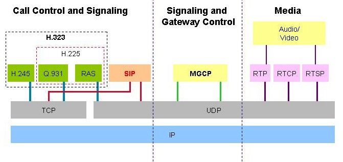
Abstract
The use of wireless networks has extended beyond simple text and data transmission.

With the increasing need for transmission of audio and video data across networks (wired

and wireless alike), the need to enhance the Quality of Service (QoS) of multimedia

transmission has also increased. QoS refers to the concept of being able to control and

measure data transmission rates, or throughput, and error rates.

Wireless networks offer the benefits of increased productivity, easier network expansion,

flexibility, and lower the cost of ownership. On the other hand, wireless data networks

present a more constrained communication environment compared to wired networks.

Because of fundamental limitations of power, available spectrum and mobility, wireless

data networks tend to have less bandwidth, more latency, less connection stability, and

less predictable availability. While fundamentals of communication and security of wired

and wireless networks are largely similar, the limitations of WLANs impose more

constraints on the quality of service and security of wireless networks.

In this research project, we studied the inherent limitations of wireless networks,

especially in the areas of QoS and security, as compared to wired standards. We used

VoIP as the multimedia benchmarking environment to explore the differences in the

quality of service of a wireless vs. a wired network and attempt to identify the main

challenge areas for enhancing the QoS of VoIP in a WLAN.

QoS of VoIP over WLAN                                                              Page ii
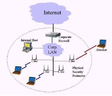
Table of Contents
Abstract ...............................................................................................................................ii
Table of Contents ...............................................................................................................iii
Table of Figures .................................................................................................................iv
Introduction ......................................................................................................................... 5
Wireless LAN Technology.................................................................................................. 7
     The Need For Wireless LANS .................................................................................... 7
     How Wireless LANs Work ......................................................................................... 8
   IEEE 802.11 Standard ................................................................................................... 10
     IEEE - 802.11a and 802.11b ..................................................................................... 11
   Wireless Network Security............................................................................................ 13
     An Example of a Security Attack in a WLAN with firewall .................................... 14
     VoIP Vulnerabilities - Security ................................................................................. 15
   IEEE 802.1x and The Extensible Authentication Protocol ........................................... 19
     How RADIUS Works in the 802.1X Environment................................................... 19
     EAP Authentication Types........................................................................................ 21
Voice Over IP (VoIP)........................................................................................................ 23
     Why use Voice over IP?............................................................................................ 23
   VoIP Network Components .......................................................................................... 24
   VoIP Protocols and Standards....................................................................................... 26
     The SIP Protocol ....................................................................................................... 26
     SIP Call Flow ............................................................................................................ 27
     The H.323 Protocol ................................................................................................... 28
     H.323 Call Flow ........................................................................................................ 29
   VoIP Challenges............................................................................................................ 31
Quality Of Service (Qos)................................................................................................... 32
     Factors affecting QoS................................................................................................ 33
     QoS Enabling Technologies...................................................................................... 36
QoS Testbed Implementation............................................................................................ 38
   Testbed Hardware Configuration .................................................................................. 38
   Testbed Software Configuration ................................................................................... 39
     Software Components ............................................................................................... 39
     The VOCAL System ................................................................................................. 40
     VOCAL Server Modules........................................................................................... 40
     QoS Measurement Tools........................................................................................... 43
QoS Test Plan and Results ................................................................................................ 45
     Testing Scenarios ...................................................................................................... 45
     Test Results ............................................................................................................... 45
Conclusion......................................................................................................................... 51
Appendix A: Inter-packet Times in Milliseconds ............................................................. 52
Appendix B: Jitter Times in Milliseconds......................................................................... 56
Appendix C: Troubleshooting Tips................................................................................... 60
References ......................................................................................................................... 62

QoS of VoIP over WLAN                                                                                                           Page iii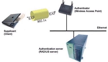
Table of Figures
Figure 1: How a Wireless LAN Works............................................................................... 9
Figure 2: Multiple access points and roaming .................................................................... 9
Figure 3: The Parking Lot Attack ..................................................................................... 14
Figure 4: Hacking WEP .................................................................................................... 17
Figure 5: EAP Authentication ........................................................................................... 19
Figure 6: Hybrid PSTN/VoIP Network............................................................................. 24
Figure 7: SIP, H.323, and MGCP Protocols ..................................................................... 26
Figure 8: SIP Call Flow..................................................................................................... 28
Figure 9: H.323 Call Flow................................................................................................. 30
Figure 10: Testbed Hardware Configuration .................................................................... 39
Figure 11: VOCAL System Overview .............................................................................. 41
Figure 12: VOCAL Call Initiation .................................................................................... 42
Figure 13: VOCAL Call Establishment ............................................................................ 43
Figure 14: Ethernet to Wireless (802.11a vs. 802.11b)..................................................... 46
Figure 15: Ethernet to Wireless (802.11b vs. 802.11b + security) ................................... 47
Figure 16: Wireless to Wireless (802.11a vs. 802.11b) .................................................... 48
Figure 17: Wireless to Wireless (802.11b vs. 802.11b + security) ................................... 50
Figure A-1: Ethernet-Ethernet........................................................................................... 52
Figure A-2: Ethernet-802.11a ........................................................................................... 52
Figure A-3: Ethernet-802.11b ........................................................................................... 53
Figure A-4: Ethernet-802.11b + security .......................................................................... 53
Figure A-5: 802.11b-802.11b............................................................................................ 54
Figure A-6: 802.11b-802.11b + security........................................................................... 54
Figure A-7: 802.11a-802.11a ............................................................................................ 55
Figure B-1: Ethernet-Ethernet........................................................................................... 56
Figure B-3: Ethernet-802.11b ........................................................................................... 57
Figure B-4: Ethernet-802.11b + security .......................................................................... 57
Figure B-5: 802.11b-802.11b ............................................................................................ 58
Figure B-7: 802.11a-802.11a ............................................................................................ 59

QoS of VoIP over WLAN                                                                                                 Page iv
Introduction
The proliferation of the Internet across geographic boundaries gave rise to the creation of

a new application: Voice over IP (VoIP), that enables two users connected to Internet to

have a voice conversation. Voice over IP technology refers to the concept of using the

well-established IP networks (e.g. internet), as backbone for carrying real time voice

communications. The voice transferred over the Internet exhibits different characteristics

than voice transferred through the Public Service Telephone Network (PSTN) and

requires certain provisions in the network.

With a paradigm shift of IP networks from pure data networks to a unified data and

voice, multimedia network has significantly reduced the voice communications costs

leading to a growing demand among end-users. Further with the explosive growth in

wireless networks, voice communications over wireless networks presents unique

challenges. Both the enterprise and consumer markets are now beginning to demand data-

intensive, time-sensitive movement of things like audio and video around a WLAN.

Voice applications have different characteristics and requirements from those of

traditional data applications. Because they are innately real-time, voice applications are

highly sensitive to delays in speech and crispy sounds. Thus strict measures for QoS are

needed to ensure the possibility of performing better VoIP calls with higher quality. In

addition, the inherent problems with security in WLANs pose additional challenges in

regard to VoIP that need to be addressed.

Looking into the importance and growth in the VoIP technology and the wireless

networks, we in our project, have studied the inherent limitations of wireless networks, in

the areas of QoS and security, as compared to wired standards and used VoIP as the

QoS of VoIP over WLAN                                                                Page 5
multimedia benchmarking environment to explore the differences in the quality of service

of a wireless vs. a wired network and made an attempt to identify the main challenge

areas for enhancing the QoS of VoIP in a WLAN.

This paper presents the details of a research experiment we conducted to measure the

effects of using the VoIP and wireless technologies separately and combined. The paper

introduces the technical background of each of these technologies, and then presents the

experiment testbed and its results and concludes with an analysis of the results and a

conclusion.

We would like to extend our thanks and acknowledgments to several people who helped

make this testbed implementation possible: Dr. Chow for providing the testbed hardware

and making the networking lab at UCCS available for our tests; Paul Fong and Ganesh

Komar Godavari for setting up the wireless access point and the RADIUS server. We

would also like to extend special thanks to Daniel Hertrich (http://www.daniel-

hertrich.de/) for providing the QoS measurement tools he used in a similar research

project [13] to evaluate QoS of VoIP over WLAN.

QoS of VoIP over WLAN                                                             Page 6
Wireless LAN Technology
Wireless local area networks (wireless LANs, or WLANs) are changing the landscape of

computer networking. In recent years, the proliferation of mobile computing devices,

such as laptops and personal digital assistants (PDA’s), coupled with the demand for

continual network connections without having to "plug in," are resulting in an explosive

growth in enterprise WLANs.

The Need For Wireless LANS

A wireless LAN is a flexible data communications system implemented as an extension

to, or as an alternative for, a wired LAN. Using radio frequency (RF) technology,

wireless LANs transmit and receive data over the air, minimizing the need for wired

connections. Wireless LANs frequently augment rather than replace wired LAN

networks—often providing the final few meters of connectivity between a wired network

and the mobile user. Wireless LAN systems can provide LAN users with access to real-

time information anywhere in their organization. Installing a wireless LAN system can be

fast and easy and can eliminate the need to pull cable through walls and ceilings. Also

Wireless technology allows the network to go where wire cannot go. While the initial

investment required for wireless LAN hardware can be higher than the cost of wired

LAN hardware, overall installation expenses and life-cycle costs can be significantly

lower. In addition Wireless LAN systems can be configured in a variety of topologies to

meet the needs of specific applications and installations. Configurations are easily

changed and range from peer-to peer networks suitable for a small number of users to full

infrastructure networks of thousands of users that enable roaming over a broad area.

QoS of VoIP over WLAN                                                                  Page 7
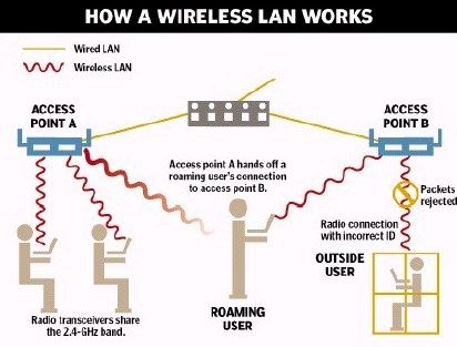
How Wireless LANs Work

At its simplest, wireless LAN technology, no matter which standard it adheres to, lets

computers communicate with the rest of a local area network via radio signals rather than

over wires. There are two key components. First is the access point, or AP, which is the

last wired stop on your network. Connected to the rest of the network via Ethernet cable,

the AP translates the wired network traffic into radio signals and transmits it out via

either the 2.4-GHz band (for 802.11b products) or the 5-GHz band (802.11a products).

The signals are picked up by laptops or desktops with either removable or permanently

embedded wireless-network interface cards. Figure 1 gives an overview of how a

wireless LAN works. Access points have a finite range, on the order of 500 feet indoor

and 1000 feet outdoors. An access point’s transmission range is called a “microcell.”

In a very large facility such as a warehouse, or on a college campus it will probably be

necessary to install more than one access point. Access point positioning is accomplished

by means of a site survey. The goal is to blanket the coverage area with overlapping

coverage cells so that clients might range throughout the area without ever losing

network contact (Figure 2). The ability of clients to move seamlessly among a cluster of

access points is called roaming. Access points hand the client off from one to another in a

way that is invisible to the client, ensuring unbroken connectivity. Thus as a user roams

out of the one access point say A’s microcell into another access point B’s coverage

range, access point A hands off the connection to the B’s access point. In a setting of

overlapping microcells, clients and access points frequently check the strength and

quality of transmission.

QoS of VoIP over WLAN                                                                Page 8
Figure 1: How a Wireless LAN Works

                    Figure 2: Multiple access points and roaming

QoS of VoIP over WLAN                                              Page 9
IEEE 802.11 Standard The lack of standards has been a significant problem with wireless networking. In response to lack of standards, the Institute for Electrical and Electronic Engineers (IEEE) developed the first internationally recognized wireless LAN standard: IEEE 802.11. 802.11 wireless networks operate in one of two modes: ad-hoc or infrastructure mode. The IEEE standard defines the ad-hoc mode as Independent Basic Service Set (IBSS), and the infrastructure mode as Basic Service Set (BSS). In ad hoc mode, each client communicates directly with the other clients within the network. This mode is designed such that only the clients within transmission range (within the same cell) of each other can communicate. If a client in an ad-hoc network wishes to communicate outside of the cell, a member of the cell MUST operate as a gateway and perform routing. In infrastructure mode, each client sends all of its communications to a central station, or access point (AP). The access point acts as an Ethernet bridge and forwards the communications onto the appropriate network– either the wired network, or the wireless network. Prior to communicating data, wireless clients and access points must establish a relationship, or an association. Only after an association is established can the two wireless stations exchange data. In infrastructure mode, the clients associate with an access point. The association process is a two-step process involving three states: Unauthenticated and unassociated, Authenticated and unassociated, and Authenticated and associated. To transition between the states, the communicating parties exchange messages called management frames. QoS of VoIP over WLAN Page 10
IEEE - 802.11a and 802.11b

The most widely used IEEE standards in the industry are the 802.11a and the 802.11b.

The third standard 802.11g holds promise but has not yet been ratified by the IEEE. Like

802.11a, 802.11g has a nominal maximum throughput of 54 Mbps, and because it is on

the 2.4-GHz frequency band, its products would be compatible with 802.11b products.

802.11a and 802.11b each define a different physical layer. 802.11b radios transmit at 2.4

GHz and send data up to 11 Mbps using direct sequence spread spectrum modulation;

whereas, 802.11a radios transmit at 5 GHz and send data up to 54 Mbps using OFDM

(Orthogonal Frequency Division Multiplexing).

The IEEE 802.11a uses a signal modulation technique known as Coded Orthogonal

Frequency Division Multiplexing (COFDM). COFDM sends a stream of data symbols in

a massively parallel fashion over multiple sub carriers, which essentially are small slices

of RF (Radio Frequency) spectrum within a designated channel within a designated

carrier frequency band. The IEEE 802.11b standard ensures interoperability of WLAN

products from manufacturer to manufacturer. Multiple levels of encryption are supported,

including a 40-bit and 128-bit encryption. WLANs operate over the 2.4 GHz radio

frequency spectrums and transmit over a range of up to 500 feet (150 m). IEEE 802.11b

WLAN use Direct Sequence Spread Spectrum (DSSS) communication technique.

The different radio frequency and modulation types of 802.11a and 802.11b cause them

not to interoperate. For example, an end user equipped with an 802.11a radio card will

not be able to connect with an 802.11b access point. The 802.11 standard offers no

provisions for interoperability between the different physical layers.

QoS of VoIP over WLAN                                                               Page 11
Situations when 802.11b is best used:

   1. Range requirements are significant: As 802.11b will provide the least costly

       solution because of fewer access points.

   2. End users are sparsely populated. If there are relatively few end users that need to

       roam throughout the entire facility, then 802.11b will likely meet performance

       requirements because there are fewer end users competing for each access point's

       total throughput. If high performance per end user is not the major consideration,

       then 802.11a would probably be very inappropriate in this situation.

Situations when 802.11a is best used:

   1. There's need for much higher performance: The need for choosing 802.11a is to

       support higher end applications involving video, voice, and the transmission of

       large images and files. For these applications, 802.11b is not very suitable as it

       will probably not be able to keep up.

   2. Significant RF interference is present within the 2.4 GHz band: The growing use

       of 2.4 GHz wireless phones and Bluetooth devices could crowd the radio

       spectrum within ones facility and significantly decrease the performance of

       802.11b wireless LANs. The use of 802.11a operating in the 5 GHz band will

       avoid this interference.

   3. End users are densely populated: Places such as computer labs, airports, and

       convention centers need to support lots of end users in a common area competing

       for the same access point, with each user sharing the total throughput. The use of

       802.11a will handle a higher concentration of end users by offering greater total

       throughput.

QoS of VoIP over WLAN                                                              Page 12
Wireless Network Security With the added convenience of wireless access come new problems, of which security considerations continue to be a major challenge. Network infrastructure designers haven't traditionally worried too much about authentication on their wired LANs, because most wired LAN ports have been installed within relatively secure offices. However, with wireless LAN radio waves propagating throughout--and perhaps outside--the enterprise, WLANs obviously present unique challenges. Lack of security is often cited as a major barrier to the growth of e-commerce (electronic commerce) into m-commerce (mobile commerce). While fundamentals of wireless security are largely similar to those of the wired Internet, wireless data networks present a more constrained communication environment compared to wired networks. With a WLAN, transmitted data is broadcast over the air using radio waves. This means that any WLAN client within an access point (AP) service area can receive data transmitted to or from the access point. Because radio waves travel through ceilings, floors, and walls, interception and masquerading becomes trivial to anyone with a radio and hence may easily reach unintended recipients. With a WLAN, the boundary for the network has moved. Therefore without stringent security measures in place, installing a WLAN can be the equivalent of putting Ethernet ports everywhere, including the parking lot. WLAN security, involves concern in three separate issues: authentication, privacy and authorization. Focusing too much on one of these capabilities without adequately addressing the others would in no way help reduce the insecurities inherent in the wireless system. QoS of VoIP over WLAN Page 13
An Example of a Security Attack in a WLAN with firewall

The deployment of a wireless network opens a “back door” into the internal network that

permits an attacker access beyond the physical security perimeter of the organization. As

a result, the attacker can implement the “parking lot” attack; refer to figure 3 in the next

page, where the attacker sits in the organization’s parking lot and accesses hosts on the

internal network. Ironically in some cases, the existence of the firewall may make the

organization’s hosts more vulnerable to the attacker because of the mistaken premise that

the hosts are immune from attack and potential compromise.

                           Figure 3: The Parking Lot Attack

QoS of VoIP over WLAN                                                                Page 14
VoIP Vulnerabilities - Security
With the merging of packet and circuit technologies, voice communications over wireless
networks presents unique challenges in the areas of security of voice traffic.
With VOIP, voice traffic is carried over a packet-switched data network via Internet
Protocol. As a result, hackers can now use data sniffing and other hacking tools to
identify, modify, store and play back voice traffic traversing the network. A hacker
breaking into a VOIP data stream has access to a lot more calls than he would with
traditional telephone tapping. Eavesdropping is a concern for organizations using VOIP
and the consequences could be much greater. With added security threats because of the
open nature of the underlying IP network, the functional VoIP security requirements
could thus be stated as:
1. Protection of privacy of the call conversation.
2. Authentication of call end entities.
3. Protection from misuse of network resources
4. Ensuring correct billing by the service provider, and protecting billing
information from unauthorized access.
5. Protection of caller behavior or statistical information from unauthorized access
6. Protection of network servers and terminals from well-known threats such as
"denial of service" and "man in the middle attacks".
While it may not be possible to make any system completely secure, there are certain
steps that can be and must be taken to ensure that the risk of security breaches is
minimized.
QoS of VoIP over WLAN Page 15IEEE 802.11 Standard Security Mechanisms
The 802.11 standard, provides several mechanisms intended to provide a secure operating
environment. The various mechanisms are as follows:
1. Wired Equivalent Privacy protocol
The Wired Equivalent Privacy (WEP) protocol was designed to protect link-level data
during wireless transmission and provide confidentiality for network traffic using the
wireless protocol. It is considered to be the first line of defense against intruders.
WEP relies on a security key k shared between the communicating parties to protect the
body of a transmitted frame of data. Both the access and client devices use the same WEP
key to encrypt and decrypt radio signals. Thus with WEP turned on each packet
transmitted from one radio to another is first encrypted by taking the packet's data
payload and a secret 40 bit number and passing them through a shredding machine called
RC4. The resulting encrypted packet is then transmitted across the airwaves. When the
receiving station hears the packet it then uses the same 40-bit number to pass the
encrypted data through RC4 backwards, resulting in the host receiving good, useable
data. The WEP protocol is intended to enforce three main security goals:
a) To prevent casual eavesdropping, b) To protect access to a wireless network
infrastructure and c) to prevent tampering with transmitted messages; the integrity
checksum field is included for this purpose.
However it has been observed that all the above three security goals have not been
attained and the WEP protocol has been discredited on grounds that its authentication and
encryption capabilities are not considered sufficient for use in enterprise networks.
QoS of VoIP over WLAN Page 16The main problem with WEP is that the RC4 stream cipher used to encrypt the data has
been proven to be insecure. RC4 combines the 40 bit WEP key with a 24 bit random
number known as an Initialization Vector (IV) to encrypt the data. The packet sent over
the airwaves contains the IV followed by the encrypted data. By passively listening to
the encrypted traffic, and picking the repeating IVs out of the data stream, an attacker can
begin to infer what the WEP key is. Eventually enough data can be gathered that the
WEP key is cracked (Refer to figure 4 below).
Figure 4: Hacking WEP
Another problem with WEP is key management. When the WEP is enabled according to
the 802.11b standard, a network administrator must perform the time-consuming task of
entering the same keys on every device in the WLAN. If the device that uses the static
WEP keys is lost or stolen, the administrator must change the WEP key on every device
that uses the same static WEP key used by the missing device. In a large enterprise
WLAN, this can quickly become a logistical nightmare.
QoS of VoIP over WLAN Page 172. Open System Authentication. Open system authentication is the default authentication protocol for 802.11.As the name implies, open system authentication authenticates anyone who requests authentication. Essentially, it provides a NULL authentication process. With open authentication, even if a client can complete authentication and associate with an AP, the use of WEP prevents the client from sending data to and receiving data from the AP, unless the client has the correct WEP key. 3. Shared System Authentication Shared key authentication uses a standard challenge and response along with a shared secret key to provide authentication. With shared-key authentication, the AP sends the client device a challenge text packet that the client must then encrypt with the correct WEP key and return to the access point. If the client has the wrong key or no key, authentication will fail and the client will not be allowed to associate with the access point. Shared-key authentication is not considered secure, because a hacker who detects both the clear-text challenge and the same challenge encrypted with a WEP key can decipher the WEP key. 4. Access Control Lists Some WLAN vendors support authentication based on the physical address, or MAC address, of the client Network Interface Card (NIC). An access point will allow association by a client only if that client's MAC address matches an address in an authentication table used by the access point. But MAC authentication is an inadequate security measure, because MAC addresses can be forged, or a NIC can be lost or stolen. QoS of VoIP over WLAN Page 18
IEEE 802.1x and The Extensible Authentication Protocol
From the above discussion it can be seen that while traditional WLAN security that relies

on open or shared-keys, static WEP keys or MAC authentication is better than no security

at all, it is not sufficient for the enterprise organization. And all large enterprises and

organizations must invest in a robust, enterprise-class WLAN security solution.

After the IEEE recognized the shortcomings of WEP and 802.11, it came up with the

802.1x and EAP solution. The combination of 802.1x standard with the Extensible

Authentication Protocol (EAP) standard, resolves WEP's biggest liability: static user and

session keys as it provides dynamic WEP keys to wireless users. The illustration below

shows how this combination works.

                             Figure 5: EAP Authentication

How RADIUS Works in the 802.1X Environment

In the most common 802.1X WLAN environments, the access points defer to the Remote

Authentication Dial-In User Service (RADIUS) server to authenticate users and to

support particular EAP authentication types. The RADIUS server handles these

functions, and provides crucial authentication and data protection capabilities according

QoS of VoIP over WLAN                                                               Page 19
to the requirements of the EAP authentication type in use. The following steps provide a basic framework for how the transaction between the WLAN client and RADIUS server works to set up a secure WLAN connection: The client makes a connection to the access point. At this point, the client is in an unauthorized state and not given an IP address or permitted access to the network in any way. The only thing the client can do is send 802.1x messages. The client sends user credentials to the access point with EAP, and the access point forwards the request to the Remote Authentication Dial-In User Service (RADIUS) server for approval. By using the EAP to interact with an EAP-compatible RADIUS server, the access point helps a wireless client device and the RADIUS server to perform mutual authentication and derive a dynamic unicast WEP key. When mutual authentication is complete, the RADIUS server and the client determine a WEP key that is unique to the client and provides the client with the appropriate level of network access, thereby approximating the level of security in a wired switched segment to an individual desktop. The client loads this key and prepares to use it for the logon session. During the logon session, the RADIUS server encrypts and sends the WEP key, called a session key, over the wired LAN to the access point. The access point encrypts its broadcast key with the session key and sends the encrypted broadcast key to the client, which uses the session key to decrypt it. The client and access point activate WEP and use the session and broadcast WEP keys for all communications during the remainder of the session. QoS of VoIP over WLAN Page 20
EAP Authentication Types

There is more than one type of EAP authentication, but the access point behaves the same

way for each type: it relays authentication messages from the wireless client device to the

RADIUS server and from the RADIUS server to the wireless client device. Some of the

commonly deployed EAP authentication types include:

a. EAP-TLS (Transport Layer Security): EAP-TLS – the security method used in the

   802.1X client in Windows XP – provides very strong security, but requires that each

   WLAN user be running a client certificate. EAP-TLS provides for certificate-based,

   mutual authentication of the client and the network. It relies on client-side and server-

   side certificates to perform authentication; dynamically generated user- and session-

   based WEP keys are distributed to secure the connection.

b. EAP-TTLS: Funk Software and Certicom have jointly developed EAP-TTLS

   (Tunneled Transport Layer Security). EAP-TTLS is an extension of EAP-TLS,

   however unlike EAP-TLS, EAP-TTLS requires only server-side certificates,

   eliminating the need to configure certificates for each WLAN client. In addition, it

   supports legacy password protocols, so you can deploy it against your existing

   authentication system (such as tokens or Active Directories). It securely tunnels client

   authentication within TLS records, ensuring that the user remains anonymous to

   eavesdroppers on the wireless link and the entire network to the RADIUS server.

c. EAP-Cisco Wireless. Also called LEAP (Lightweight Extensible Authentication

   Protocol), this EAP authentication type is used primarily in Cisco WLAN APs.

   Though easy to set up and manage, it does not provide strong credential security over

   the wireless link, leaving password credentials vulnerable to dictionary attack. It

QoS of VoIP over WLAN                                                                Page 21
encrypts data transmission using dynamically generated WEP keys, and supports

   mutual authentication.

Thus security seems to be an even greater problem for wireless networks. Firstly, since

radio signals travel through the open atmosphere where individuals who are constantly on

the move can intercept them — they are difficult to track down. Secondly, wireless

solutions are, almost universally, dependent on public-shared infrastructure where you

have much less control of, and knowledge about, the security discipline employed.

QoS of VoIP over WLAN                                                               Page 22
Voice Over IP (VoIP)
The spread of Internet and its underlying communication protocols IP gave rise to the

notion of everything over IP. One of the applications that is experiencing high growth

and popularity is Voice over IP (VoIP).

Why use Voice over IP?

Voice over IP is gaining success because of multiple reasons:

1. Lower equipment cost:

PSTN PBXs cost millions of dollars and are very slow to change to allow the addition of

new features. IP network components are less expensive and enjoy higher interoperability

allowing equipments to be sourced from multiple vendors who are very competitive

reducing the cost of these equipments. Also, the cycle of rolling out new features is

counted in months not years as in the case of switching centers.

2. Integration of voice and data:

The use of one network to carry both voice and data allows savings of management and

operational manpower, operational costs and the efficient use of communication links

between different sites. Also the integration of voice and data allows the creation of new

sets of applications that make use of both. For example: click to talk, voice mail, video

conferencing, …

3. Lower bandwidth requirement:

PSTN uses line switching technology. In North America, a 64Kbs full duplex circuit is

reserved between the two ends of the conversation even though this bandwidth is not

fully utilized most of the time, because only one party might be talking at a time and

there are many silence moments during a conversation. Also, line switching does not

QoS of VoIP over WLAN                                                              Page 23
allow the shared use of a valuable resource, namely communication lines between the

different exchanges. In addition, the developments in compression technologies have

reduced the bandwidth needed to carry voice to less than 7 kbs without a noticeable loss

of voice quality.

4. The widespread availability of IP:

IP networks are widely available geographically across continents and within most

countries. This allows most people to have access to a PC linked to the Internet. Also the

availability of gateways to/from PSTN allows calls to use VoIP even for a portion of call,

the initiating end, the terminating end, or an intermediate link. For example, a

transoceanic link can use VoIP to maximize utilization of the expensive bandwidth.

                            VoIP Network Components
Voice over IP networks in general is composed of four different types of components:

End stations, Severs, IP network and Interface to PSTN if needed. Figure 6 provides a

high-level view of a hybrid PSTN/VoIP network.

                        Figure 6: Hybrid PSTN/VoIP Network

The end stations initiate and maintain the signaling required to establish calls over the IP

network, and convert voice to data packets and vice versa.

QoS of VoIP over WLAN                                                                Page 24
Servers enable call establishment and support additional features. For example, a SIP
location server allows users to forward calls to a different location.
Links to PSTN (Gateways) allow the interface between VoIP network and PSTN
networks, if needed. Gateways perform two main tasks:
a) Convert signaling used to establish, tear down and maintain a call between
PSTN and VoIP protocols, and b) Convert voice samples at the PSTN side (8000
samples/sec) to VoIP packets and vice versa.
Gateways perform a multiple of other functions such as the exchange of billing
information and SS7 network interface. SS7 network is a management and control
network used to manage and control PSTN networks.
The Signaling Transport (sigtran) working group of the IETF defined protocols to
provide all functionality needed to support SS7 signaling over IP networks, including:
• Flow control and in-sequence delivery of signaling messages
• Identification of the originating and terminating signaling points
• Error detection, retransmission and other error correcting procedures
• Recovery from outages of components in the transit path
• Controls to avoid congestion on the Internet
• Detection of the status of peer entities
• Extensions to support security and future requirements
IP networks provide the infrastructure linking all the components together and the
necessary routing of calls and data packets between one end of the network to another.
An IP Network could be a LAN or a combination of LAN and WAN links connecting
two stations at the far ends of the globe.
QoS of VoIP over WLAN Page 25VoIP Protocols and Standards
Most VoIP signaling protocols run over TCP/IP networks, which provide a full reliable
transfer of data packets between clients or between clients and servers. The transfer of
real-time packets (RTP protocol) is carried over UDP, which does not provide a loss-less
packets transfer between the two ends of the link, because re-sending lost packets is
unnecessary since they usually arrive too late to be used in the voice stream.
Different standards are emerging to specify VoIP protocols. The following are the main
standards used in this area: SIP, H.323, and MGCP. A brief introduction is included
hereafter for the two most popular protocols (SIP and H.323). Figure 7 gives a high-level
view of the SIP, H.323, and MGCP protocols and their interaction with the TCP/IP stack.
Figure 7: SIP, H.323, and MGCP Protocols
The SIP Protocol
The Session Initiation Protocol (SIP) is an ASCII-based, peer-to-peer application layer
protocol that defines initiation, modification and termination of interactive, multimedia
QoS of VoIP over WLAN Page 26communication sessions between users. SIP is developed by the Internet Engineering
Task Force (IETF) and is derived from Hyper-text Transfer Protocol (HTTP) and Simple
Mail Transfer Protocol (SMTP). SIP is defined as a client-server protocol, in which
requests are issued by the calling client and responded to by the called server, which may
in itself be a client for other aspects of the same call. SIP is not dependent on TCP for
reliability but rather handles its own acknowledgment and handshaking. This makes it
possible to create an optimal solution that is highly adjusted to the properties of VoIP.
SIP Call Flow
Establishing communication using SIP usually occurs in six steps (figure 8):
1. Registering, initiating and locating the user.
2. Determining the media to use.
3. Determining the willingness of the called party to communicate (accept or reject).
4. Call setup.
5. Call modification or handling.
6. Call termination.
The SIP protocol defines the following methods to establish a call:
INVITE - Initiates a call by inviting user to participate in session.
ACK - Confirms that the client has received a response to an INVITE request.
BYE - Indicates termination of the call.
CANCEL - Cancels a pending request.
REGISTER – Registers the user agent.
OPTIONS – Used to query the capabilities of a server.
INFO – Used to carry out-of-bound information, such as DTMF digits.
QoS of VoIP over WLAN Page 27Figure 8: SIP Call Flow SIP was designed for integration with existing IETF protocols, scalability and simplicity, mobility, and easy feature and service creation. The H.323 Protocol The H.323 standard is a suite of VoIP protocols and techniques developed by the International Telecommunication Community (ITU). The organization’s goal is to produce standards and recommendations so that a homogenous telephone network will be available all over the world. The H.323 offers solutions for audio, video and multipoint data transfers. The H.323 protocol suite includes: a) H.245 - a protocol for capabilities advertisement, media channel establishment and conference control, b) H.225 - a protocol for call control, c) Q.931 - a protocol for call control and call setup, and d) RAS – a protocol for registration, admission and status used for communicating between an H.323 endpoint and a gatekeeper. QoS of VoIP over WLAN Page 28
H.323 Call Flow

H.323 defines several protocol exchange stages between the terminals, gateways, and

gatekeepers before an audio connection can be established. The following step are

performed in order to setup a connection between two terminals:

   1. Gatekeeper discovery/terminal registration (H.225-RAS).

   2. Routed call signaling between the terminals through the gatekeeper (H.225-RAS

       and H.225-Q.931)

   3. Initial communications and capability exchange (master slave detection and

       capability exchange (H.245).

   4. Establish audio communication (open logical channel) (H.245)

   5. Audio transmission (RTP/RTCP)

Figure 9 describes the call flow to establish a connection between two H.323 clients:

   1. Both endpoints have previously registered with the gatekeeper.

   2. Terminal A initiates the call to the gatekeeper. (RAS messages are exchanged).

   3. The gatekeeper provides information for Terminal A to contact Terminal B.

   4. Terminal A sends a SETUP message to Terminal B.

   5. Terminal B responds with a Call Proceeding message and also contacts the

       gatekeeper for permission.

   6. Terminal B sends an Alerting and Connect message.

   7. Terminal B and A exchange H.245 messages to determine master slave, terminal

       capabilities, and open logical channels.

   8. The two terminals establish RTP media paths.

QoS of VoIP over WLAN                                                              Page 29
Figure 9: H.323 Call Flow H.323 is known for quite complex signaling, high connection setup latencies, and implementation difficulties. However, H.323 is widely implemented and is the primary common denominator for all VoIP. SIP and H.323 provide similar functionality: Call control, call setup and teardown, basic call features such as call waiting, call hold, call transfer, call forwarding, call return, call identification, or call park, and capabilities exchange. Each protocol exhibits strengths in different applications. H.323 defines sophisticated multimedia conferencing which can support applications such as whiteboarding, data collaboration, or video conferencing. SIP supports flexible and intuitive feature creation with SIP using SIP-CGI (SIP- Common Gateway Interface) and CPL (Call Processing Language). Third party call control is currently only available in SIP. Work is in progress to add this functionality to H.323. QoS of VoIP over WLAN Page 30
VoIP Challenges
The use and adoption of VoIP is faced by a multitude of challenges resulting from two

main factors. First, the Internet was not designed to transfer real time data; it is a best

effort network. Network equipment drop packets and may have queues that cause jitter in

packets transfer delays. Also routing is more time consuming when compared to

switching. Network delays and loss of packets affect the quality of service of VoIP.

These factors are discussed in more detail later. Multiple efforts are undergoing in

various directions to reduce or eliminate those QoS variables, among which are

Reservation Protocols (RSVP), design separate high priority queues for real time traffic

and the use of a mix between routing and switching (MPLS) to speed up packets through

routing points.

Second, PSTN has grown and added multiple features that are different to emulate. The

main challenge that exists presently is the support of 911 emergency services.

Emergency workers responding to a 911 call can determine the exact location of the

originator of the call, because of the tight relation between telephone number and

geographic locations. Calls originating from a VoIP client are very difficult to correlate

to a geographic location due to the lack of geographic structure in IP addresses, and the

dynamism of IP networks. Several efforts are undergoing to solve this problem but it still

posses a great challenge.

In addition, there is a growing concern about the privacy and security of VoIP

conversations. As discussed, with the ability of capturing voice packets using a network

sniffer, eavesdropping is easier in VoIP networks than it is in PSTN. Using wireless

networks combined with VoIP further complicates these VoIP challenges.

QoS of VoIP over WLAN                                                               Page 31
Quality Of Service (Qos)
Quality of Service (QoS) refers to the concept of being able to control and measure data

transmission rates, or throughput, and error rates. Specifically, QoS refers to the ability of

a network to provide better, more predictable service to selected network traffic over

various underlying technologies, including IP-routed networks.

Traditionally networks did not require strict measures for QoS because the data wasn't

multimedia and the end-user could not notice or be materially affected by latencies.

But, as the use of WLANs spread far beyond simple data transfer to intense multimedia

applications, the need to address Quality of Service (QoS) issues becomes extremely

important. Both the enterprise and consumer markets are now beginning to demand data-

intensive, time-sensitive movement of things like audio and video around a WLAN.

Voice applications have different characteristics and requirements from those of

traditional data applications. Because they are innately real-time, voice applications

tolerate minimal delay in delivery of their packets. Additionally, they are intolerant of

packet loss, out-of-order packets, and jitter. To effectively transport voice traffic over IP,

mechanisms are required that ensure reliable conveyance of packets with low and

controlled latency. Thus the primary goal in the context of VoIP QoS, then would be to

provide dedicated bandwidth, controlled jitter and latency (required by some real-time

and interactive traffic), and improved loss characteristics.

QoS of VoIP over WLAN                                                                  Page 32
Factors affecting QoS

1. Packet loss

UDP cannot provide a guarantee that packets will be delivered at all, much less in order.

Packets will be dropped under peak loads and during periods of congestion. Due to time

sensitivity of voice transmissions, the normal TCP based retransmission schemes are not

appropriate. Approaches used to compensate for packet loss include interpolation of

speech by replaying the last packet and sending redundant information. Packet losses

greater than 10 percent are generally intolerable, unless the encoding scheme provides

extraordinary robustness.

2. Jitter

In as much as IP networks cannot guarantee the delivery time of data packets (or their

order), the data will arrive at very inconsistent rates. The variation in inter-packet arrival

rate is jitter, which is introduced by variable transmission delays over the network.

Removing jitter to allow an equable stream requires collecting packets and storing them

long enough to permit the slowest packets to arrive in time to be played in the correct

sequence. The jitter buffer is used to remove the packet delay variation that each packet

encounters transiting the network. Each jitter buffer adds to the overall delay.

3. Latency

Latency is the time delay incurred in speech by the Internet Protocol (IP) telephony

system. One-way latency is the amount of time measured from the moment the speaker

utters a sound until the listener hears it. Round trip latency is the sum of the two one-way

latency figures that compose the user’s call. The lower the latency, the more natural

interactive conversation becomes; accordingly, the additional delay incurred by the VoIP

QoS of VoIP over WLAN                                                                   Page 33
system is less noticeable. When coders/decoders (codecs) in VoIP terminals compress

voice signals they introduce three types of delay: Processing, or algorithmic, delay – the

time required for the codec to encode a single voice frame, Look ahead delay – the time

required for a codec to examine part of the next frame while encoding the current frame

(most compression schemes require look ahead) and Frame delay – the time required for

the sending system to transmit one frame.

The following are some of the commonly used ITU-T standard codecs and the amount of

one-way delay that they introduce are:

•   G.711 uncompressed 64 Kbps speech adds negligible delay

•   G.729 encodes speech at 8 Kbps and adds a one-way delay of about 25 ms.

•   G.723.1 encodes speech at 6.4 Kbps or 5.3 Kbps and adds a one-way delay of about

    67.5 ms.

In general, it can be seen that greater levels of compression introduce more delay and

require lower network latency to maintain good voice quality. Most VoIP sessions

require one-way latency of not more than about 200 milliseconds. This delay budget is

reduced by any delays introduced by codecs in the end systems. When round-trip delays

exceed approximately 300 ms., natural human conversation becomes difficult.

Latency/Delay introduces two other difficulties -- echo and talker overlap. Echo is caused

by the signal reflections of the speaker's voice from the far end telephone equipment back

into the speaker's ear. Echo becomes a significant problem when the round trip delay

becomes greater than 50 milliseconds. Since echo is perceived as a significant quality

problem, Voice over Packet systems must address the need for echo control and

implement some means of echo cancellation. Secondly, Talker overlap (or the problem of

QoS of VoIP over WLAN                                                              Page 34
one talker stepping on the other talker's speech) becomes significant if the one-way delay
becomes greater than 250 msec. The end-to-end delay budget is therefore the major
constraint and driving requirement for reducing delay through a packet network.
To support VoIP traffic consistently and reliably, a network must therefore be able to
provide three things:
• Packet-forwarding latency that does not exceed the maximum tolerable level for a
VoIP conversation
• Packet-forwarding jitter, which is the variation in latency over time that does not
exceed the maximum tolerable level to sustain a VoIP session
• Guaranteed network bandwidth and capacity for VoIP sessions during periods of
network congestion
In other words, a network needs to provide performance – low latency and low jitter –
and protection – to maintain stringent measures of quality of service.
From the above discussion of QoS, it can be seen that Assurance of Quality of Service is
critical for proper operation of a VoIP network. The evolution of IP based applications
place more stress and require more sophistication in equipment designed to support these
applications over real world networks, while delivering services at similar reliability
levels to those experienced over non-integrated traditional networks. The ability to have a
flexible mechanism that enables a user to tailor the QoS policy to his specific needs is a
critical component of an overall integrated network.
QoS of VoIP over WLAN Page 35QoS Enabling Technologies
QoS, as perceived by the user, is an end-to-end experience to deliver the best voice
quality during a conversation, i.e., it is a collective measure of the level of service
delivered to a customer. QoS can be characterized by several performance criteria, such
as service availability, throughput, connection setup time, percentage of successful
transmissions, etc.. In order to overcome the shortcomings of transmitting voice over IP
networks, a number of technical solutions and protocols are developed to improve QoS of
VoIP. The following is a survey of some of these technologies and is far from being an
exhaustive list of such currently available or under development solutions.
• Real-Time Transport Protocol (RTP – RFC 1889) operates on top of UDP. RTP
packets include a sequence number in order to deliver packets in the correct order,
and a timestamp that is delivered to the destination application in order to ensure the
synchronization of the packets to correspond to the sampling rate used at the source.
• Resource Reservation Protocol (RSVP – RFC 205) enables resources to be reserved
for a given session prior to any attempt to exchange media between the participants.
RSVP is a part of the IETF integrated services suite.
• Differentiated Service (DiffServ – RFC 2475) provides a means for prioritizing
different types of traffic by defining a particular type of forwarding (EF or AF).
• RFC 2598 specifies EF, a service in which a given traffic stream is assigned a
departure rate greater than the arrival rate, thereby removing queuing delays.
• RFC 2597 defines AF, a service in which packets from a given source are forwarded
with a high probability provided that the traffic from that source does not exceed a
preassigned maximum.
QoS of VoIP over WLAN Page 36You can also read