Installation and User Guide - CB-6404/CB-6408 Bullet Cameras - NetX
←
→
Page content transcription
If your browser does not render page correctly, please read the page content below
Quasar™
            Installation and
            User Guide
            CB-6404/CB-6408
            Bullet Cameras

CB-640x Installation and User Guide Revision 100                                                    February 2021
                                This document does not contain any export-controlled information.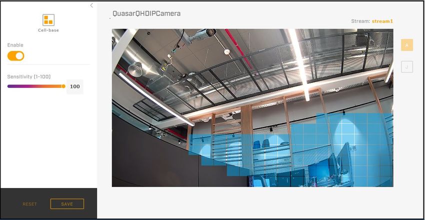
© 2021 FLIR Systems, Inc. All rights reserved. No parts of this material may be copied, translated, or
transmitted (in any medium) without the prior written permission of FLIR Systems, Inc.
Names and marks appearing on the products herein are either registered trademarks or trademarks of
FLIR Systems, Inc. and/or its subsidiaries. All other trademarks, trade names, or company names
referenced herein are used for identification only and are the property of their respective owners.
Protected by one or more patents and patent applications. Learn more here: www.flir.com/patentnotice.
Photographs and images appearing in this manual may have been modified for illustrative purposes
using commercial image editing software and may not always reflect an actual product configuration.
The contents of this document are subject to change without notice.
For additional information visit www.flir.com or write to:

FLIR Systems, Inc.
6769 Hollister Ave.
Goleta, CA 93117
Phone: 888.747.FLIR (888.747.3547)
International: +1.805.964.9797

For technical assistance, please call us at +1.888.388.3577 or visit the Service & Support page at
www.flir.com/security.

Important Instructions and Notices to the User:
Modification of this device without the express authorization of FLIR Commercial Systems, Inc. may void
the user’s authority under FCC rules to operate this device.

Note 1: This equipment has been tested and found to comply with the limits for a Class B digital device,
pursuant to Part 15 of the FCC rules. These limits are designed to provide reasonable protection against
harmful interference in a residential installation. This equipment generates, uses, and can radiate radio
frequency energy and, if not installed and used in accordance with the instructions, may cause harmful
interference to radio communications. However, there is no guarantee that the interference will not occur
in a particular installation. If this equipment does cause harmful interference to radio or television
reception, which can be determined by turning the equipment off and on, the user is encouraged to try to
correct the interference by one or more of the following measures:
Reorient or relocate the receiving antenna;
Increase the separation between the equipment and receiver;
Connect the equipment into an outlet on a circuit different from that of the receiver; and/or
Consult the dealer or an experienced radio/television technician for help.

Note 2: This equipment was tested for compliance with the FCC limits for a Class B digital device using
a shielded cable for connecting the equipment to an analog video output to a monitor and using a
shielded USB cable for connecting the equipment to a personal computer. When making such
connections, shielded cables must be used with this equipment.

Industry Canada Notice:
This Class B digital apparatus complies with Canadian ICES-003.

Avis d’Industrie Canada:
Cet appareil numerique de la classe B est conforme a la norme NMB-003 du Canada.

CB-640x Installation and User Guide Revision 100                   February 2021                         ii
                                This document does not contain any export-controlled information.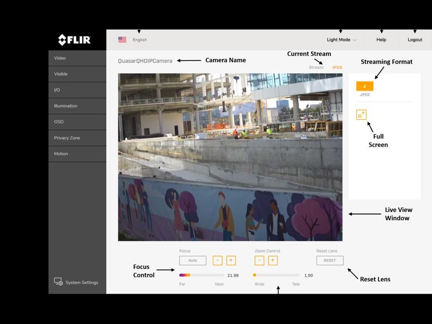
Proper Disposal of Electrical and Electronic Equipment (EEE)

                       The European Union (EU) has enacted Waste Electrical and Electronic Equipment
                       Directive 2002/96/EC (WEEE), which aims to prevent EEE waste from arising; to
                       encourage reuse, recycling, and recovery of EEE waste; and to promote
                       environmental responsibility.

                    In accordance with these regulations, all EEE products labeled with the “crossed out
                    wheeled bin” either on the product itself or in the product literature must not be
disposed of in regular rubbish bins, mixed with regular household or other commercial waste, or by other
regular municipal waste collection means. Instead, and in order to prevent possible harm to the
environment or human health, all EEE products (including any cables that came with the product) should
be responsibly discarded or recycled.

To identify a responsible disposal method nearby, please contact the local waste collection or recycling
service, the original place of purchase or product supplier, or the responsible government authority in the
area. Business users should contact their supplier or refer to their purchase contract.

Document History
    Revision     Date                                    Comment
      100        February 2021                           Initial FLIR Release

CB-640x Installation and User Guide Revision 100                   February 2021                        iii
                                This document does not contain any export-controlled information.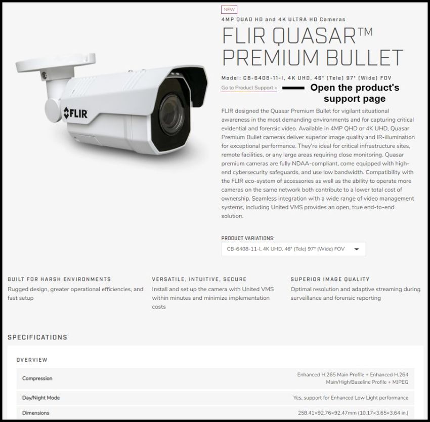
Table of Contents
    Document Scope and Purpose .............................................................................................. 1
    Introduction .............................................................................................................................. 6
    2.1       Features .......................................................................................................................... 7
    2.2       Accessing Product Information from the FLIR Website .................................................. 7
    2.3       Camera Dimensions ....................................................................................................... 9
    Installation .............................................................................................................................. 10
    3.1       Supplied Components .................................................................................................. 10
    3.2       Pre-Installation Checklist .............................................................................................. 10
    3.3       Outdoor Mounting Recommendations .......................................................................... 11
    3.4       Hardware Description ................................................................................................... 11
     3.4.1        System Cable ........................................................................................................... 12
     3.4.2        Internal Interfaces ..................................................................................................... 12
    3.5       Powering the Camera ................................................................................................... 14
    3.6       Initial Configuration ....................................................................................................... 15
     3.6.1        Discover the Camera and Configure for Networking................................................ 16
     3.6.2        Change the Video Format (Optional) ....................................................................... 18
    3.7       Mounting the Back Box and Routing the Cables .......................................................... 19
    3.8       Mounting and Aiming the Camera ................................................................................ 19
     3.8.1        Attaching the Camera to the Back Box .................................................................... 19
     3.8.2        Adjusting the Sun Shield .......................................................................................... 20
     3.8.3        Aiming the Camera ................................................................................................... 21
    3.9       Completing Camera Setup ........................................................................................... 22
    3.10      Attaching the Camera to a Supported VMS ................................................................. 22
    Operation ................................................................................................................................ 23
    4.1       Accessing the Camera’s Web Page ............................................................................. 23
    4.2       View Settings Home Page ............................................................................................ 24
    4.3       Video Page ................................................................................................................... 25
     4.3.1        Viewing Live Video using a Media Player ................................................................ 31
    4.4       Visible Page .................................................................................................................. 32
    4.5       I/O Page ........................................................................................................................ 37
    4.6       Illumination Page .......................................................................................................... 38
    4.7       OSD Page ..................................................................................................................... 39
    4.8       Privacy Zone Page ....................................................................................................... 40
    4.9       Motion Page .................................................................................................................. 42
    Configuration ......................................................................................................................... 44
    5.1       Network Page ............................................................................................................... 44
    5.2       RTSP Page ................................................................................................................... 47
    5.3       Date & Time Page ........................................................................................................ 47
    5.4       Users Page ................................................................................................................... 49
    5.5       FTP Page ...................................................................................................................... 50
    5.6       SD Card Page ............................................................................................................... 51

CB-640x Installation and User Guide Revision 100                                 February 2021                                                        iv
                                       This document does not contain any export-controlled information.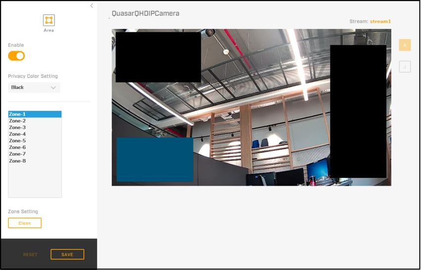
5.7       Alarm Page ................................................................................................................... 52
      5.8       Audio Page ................................................................................................................... 57
      5.9       I/O Devices Page .......................................................................................................... 57
      5.10      Sound Page .................................................................................................................. 58
      5.11      Snapshot Page ............................................................................................................. 59
      5.12      Recording Page ............................................................................................................ 59
      5.13      Email Page.................................................................................................................... 60
      5.14      Cyber Page ................................................................................................................... 61
       5.14.1       Certificates ................................................................................................................ 62
       5.14.2       SNMP ....................................................................................................................... 64
       5.14.3       802.1X ...................................................................................................................... 65
       5.14.4       TLS/HTTPS .............................................................................................................. 66
       5.14.5       Ports ......................................................................................................................... 67
       5.14.6       IP Filter ..................................................................................................................... 68
      5.15      Firmware & Info Page ................................................................................................... 68
Appendices ................................................................................................................................... 71
                Technical Specifications ............................................................................................... 72
                Network Settings ........................................................................................................... 73
                Troubleshooting ............................................................................................................ 74
                Acronyms and Abbreviations ........................................................................................ 76
                Mounting Accessories ................................................................................................... 77
                Detaching the Camera from the Adapter Plate............................................................. 78

CB-640x Installation and User Guide Revision 100                                    February 2021                                                        v
                                         This document does not contain any export-controlled information.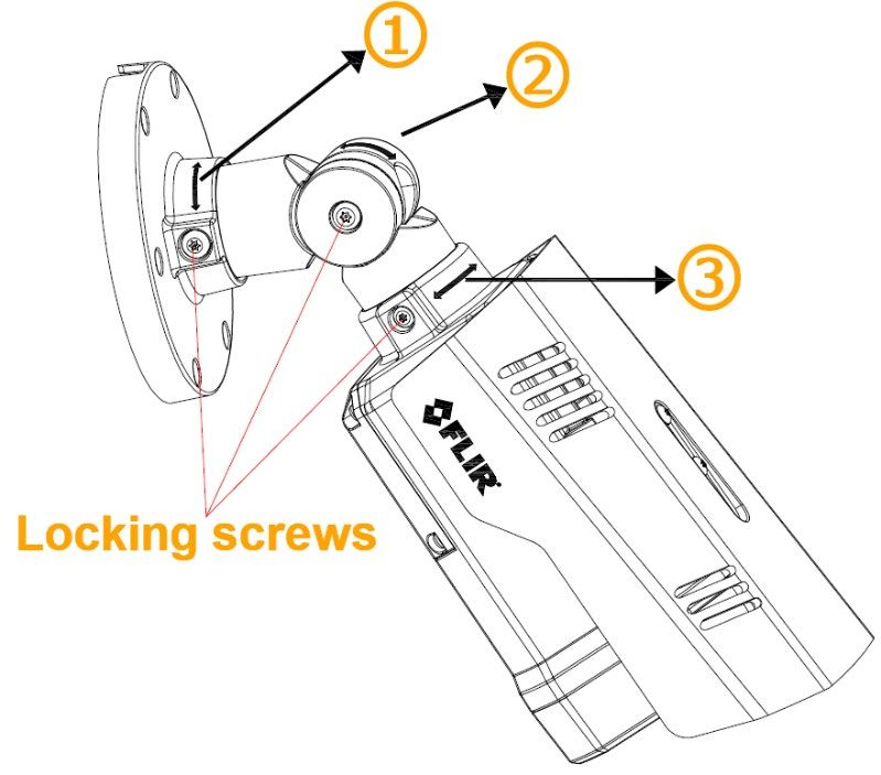
List of Figures
Figure 1: CB-640x Bullet Camera with Sun Shield .................................................................................... 6
Figure 2: Visible Security Cameras Page on FLIR.com ............................................................................ 7
Figure 3: FLIR Quasar™ Premium Bullet Details Page on FLIR.com ....................................................... 8
Figure 4: FLIR Quasar™ Premium Bullet Support Page ........................................................................... 8
Figure 5: Side Dimensions ......................................................................................................................... 9
Figure 6: Front Dimensions ........................................................................................................................ 9
Figure 7: Hardware .................................................................................................................................. 11
Figure 8: System Cable............................................................................................................................ 12
Figure 9: Internal Interfaces ..................................................................................................................... 13
Figure 10: PoE Connection ...................................................................................................................... 14
Figure 11: DNA Discover List ................................................................................................................... 16
Figure 12: DNA - Select Login ................................................................................................................. 17
Figure 13: DNA - Login Window .............................................................................................................. 17
Figure 14: DNA - IP Setup Window ......................................................................................................... 17
Figure 15: DNA - IP Setup Window - Status Ok ...................................................................................... 18
Figure 16: DNA - Change Video Format Window .................................................................................... 18
Figure 17: RJ45 Insertion Tool ................................................................................................................. 19
Figure 18: Single Cable Rubber Seal ...................................................................................................... 19
Figure 19: Alignment Triangles ................................................................................................................ 20
Figure 20: Attach Camera to Back Box .................................................................................................... 20
Figure 21: Mounting Complete ................................................................................................................. 20
Figure 22: Adjusting the Sun Shield ......................................................................................................... 20
Figure 23: Supporting the Camera ........................................................................................................... 21
Figure 24: Aiming the Camera ................................................................................................................. 21
Figure 25: Aligning the Toothed Surfaces................................................................................................ 22
Figure 26: Camera Web Page Login Screen ........................................................................................... 23
Figure 27: Camera Web Page First-Time Login ...................................................................................... 24
Figure 28: View Settings Home Page (Google Chrome) ......................................................................... 24
Figure 29: Video Page ............................................................................................................................. 26
Figure 30: VLC Open Media Screen ........................................................................................................ 31
Figure 31: Media Player Screen .............................................................................................................. 32
Figure 32: Visible Page ............................................................................................................................ 32
Figure 33: Visible Page Advanced Settings > Auto Exposure Mode Settings (Auto Selected) ............... 33
Figure 34: Backlight Compensation Settings ........................................................................................... 35
Figure 35: Manual White Balance Settings .............................................................................................. 36
Figure 36: Additional Advanced Settings ................................................................................................. 36
Figure 37: I/O Page - Alarm Input Pin Settings ........................................................................................ 37
Figure 38: Alarm Output Pin - Pulse Settings .......................................................................................... 38

CB-640x Installation and User Guide Revision 100                                February 2021                                                        vi
                                        This document does not contain any export-controlled information.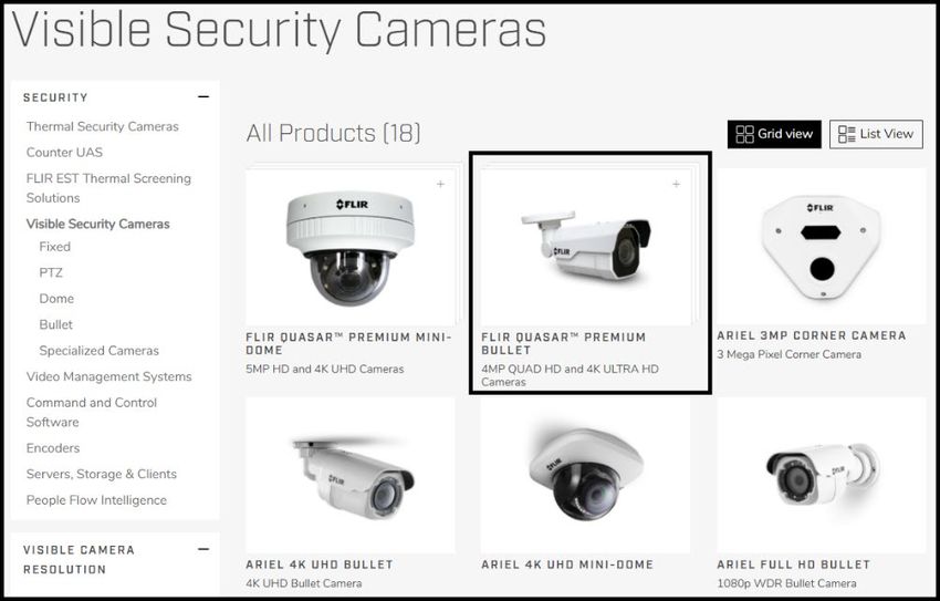
Figure 39: Alarm Output Pin - Normal Settings ................................................................................... 38
Figure 40: Illumination Page .................................................................................................................... 39
Figure 41: OSD Page - OSD1 Settings .................................................................................................... 40
Figure 42: Privacy Zone Page ................................................................................................................. 41
Figure 43: Three Privacy Zones Set Up - Zone-1 Selected ..................................................................... 41
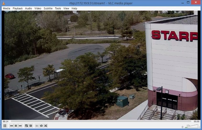
Figure 44: Motion Page ............................................................................................................................ 42
Figure 45: Motion Detection Enabled and Zone Defined ......................................................................... 43
Figure 46: System Settings Network Page - IP Mode Settings ............................................................... 44
Figure 47: QoS Settings ........................................................................................................................... 45
Figure 48: UPnP Settings......................................................................................................................... 46
Figure 49: DDNS Settings - DynDNS Selected ....................................................................................... 46
Figure 50: Additional Networking Settings ............................................................................................... 47
Figure 51: RTSP Page ............................................................................................................................. 47
Figure 52: Date & Time Page - NTP Selected ......................................................................................... 48
Figure 53: Date & Time Page - Manual Selected .................................................................................... 48
Figure 54: Users Page ............................................................................................................................. 49
Figure 55: Add User Dialog Box .............................................................................................................. 49
Figure 56: User Management .................................................................................................................. 50
Figure 57: FTP Page ................................................................................................................................ 50
Figure 58: SD Card Page – SD Card Not Inserted .................................................................................. 51
Figure 59: SD Card Page – SD Card Inserted and Files Available ......................................................... 52
Figure 60: Alarm Page ............................................................................................................................. 52
Figure 61: Rule Configuration Trigger Screen - I/O Trigger Selected ..................................................... 53
Figure 62: Rule Configuration - I/O Trigger Selected .............................................................................. 54
Figure 63: Arming Schedule Setting Screen ............................................................................................ 54
Figure 64: Arm Alarm and Enable Action Monday through Friday 8 AM-6 PM ....................................... 55
Figure 65: Modified Alarm Armed Schedule ............................................................................................ 55
Figure 66: Rule Configuration Action Screen........................................................................................... 56
Figure 67: Rule List .................................................................................................................................. 56
Figure 68: Rule List - Rule Trigger ........................................................................................................... 57
Figure 69: Audio Page ............................................................................................................................. 57
Figure 70: I/O Devices Page .................................................................................................................... 58
Figure 71: Sound Page ............................................................................................................................ 58
Figure 72: Snapshot Page ....................................................................................................................... 59
Figure 73: Recording Page - One Shot Record Status ............................................................................ 59
Figure 74: Email Page.............................................................................................................................. 60
Figure 75: Add Contact Screen ................................................................................................................ 61
Figure 76: Contact Management ............................................................................................................. 61
Figure 77: Cyber Page - Certificate Settings ........................................................................................... 62
CB-640x Installation and User Guide Revision 100 February 2021 vii
This document does not contain any export-controlled information.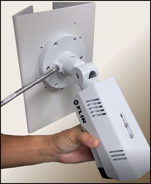
Figure 78: Certificate Generated .............................................................................................................. 63
Figure 79: Upload Certificate ................................................................................................................... 63
Figure 80: SNMP Settings........................................................................................................................ 64
Figure 81: 802.1X Settings....................................................................................................................... 66
Figure 82: TLS/HTTPS Settings .............................................................................................................. 67
Figure 83: Port Settings ........................................................................................................................... 67
Figure 84: IP Filter Settings...................................................................................................................... 68
Figure 85: Firmware & Info Page ............................................................................................................. 69
Figure 86: Detaching the Camera from the Adapter Plate ....................................................................... 78

CB-640x Installation and User Guide Revision 100                                February 2021                                                      viii
                                        This document does not contain any export-controlled information.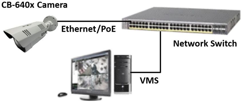
Document Scope and Purpose

     Document Scope and Purpose
The purpose of this document is to provide instructions and installation procedures for physically
connecting the CB-640x unit. After completing the physical installation, additional setup and
configurations are required before video analysis and detection can commence.

 Note
 This document is intended for use by technical users who have a basic understanding of CCTV
 camera/video equipment and LAN/WAN network connections.
 Remarque
 Ce document est destiné aux utilisateurs techniciens qui possèdent des connaissances de base des
 équipements vidéo/caméras de télésurveillance et des connexions aux réseaux LAN/WAN.

 Warning
 Installation must follow safety, standards, and electrical codes as well as the laws that apply where
 the units are being installed.
 Avertissement
 L'installation doit respecter les consignes de sécurité, les normes et les codes électriques, ainsi que la
 législation en vigueur sur le lieu d'implantation des unités.

 Disclaimer                                                 Avis de non-responsabilité
 Users of FLIR products accept full                         Il incombe aux utilisateurs des produits FLIR de
 responsibility for ensuring the suitability and            vérifier que ces produits sont adaptés et d'étudier le
 considering the role of the product detection              rôle des capacités et limites de détection du produit
 capabilities and their limitation as they apply            appliqués aux exigences uniques de leur site.
 to their unique site requirements.
                                                            FLIR Systems, Inc. et ses agents ne garantissent
 FLIR Systems, Inc. and its agents make no                  d'aucune façon que les produits sont adaptés à
 guarantees or warranties to the suitability for            l'usage auquel l'utilisateur les destine. FLIR
 the users’ intended use. FLIR Systems, Inc.                Systems, Inc. ne pourra être tenu pour responsable
 accepts no responsibility for improper use or              en cas de mauvaise utilisation ou de mise en place
 incomplete security and safety measures.                   de mesures de sécurité insuffisantes.
 Failure in part or in whole of the installer,              Le non respect de tout ou partie des procédures
 owner, or user in any way to follow the                    recommandées ou des messages
 prescribed procedures or to heed                           d'AVERTISSEMENT ou d'ATTENTION de la part de
 WARNINGS and CAUTIONS shall absolve                        l'installateur, du propriétaire ou de l'utilisateur
 FLIR and its agents from any resulting                     dégagera FLIR Systems, Inc. et ses agents de toute
 liability.                                                 responsabilité en résultant.
 Specifications and information in this guide               Les spécifications et informations contenues dans
 are subject to change without notice.                      ce guide sont sujettes à modification sans préavis.

CB-640x Installation and User Guide Revision 100                   February 2021                                     1
                                This document does not contain any export-controlled information.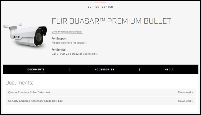
Document Scope and Purpose

  A Warning is a precautionary message that indicates a procedure or condition where there are
  potential hazards of personal injury or death.
  Avertissement est un message préventif indiquant qu'une procédure ou condition présente un risque
  potentiel de blessure ou de mort.

  A Caution is a precautionary message that indicates a procedure or condition where there are
  potential hazards of permanent damage to the equipment and or loss of data.
  Attention est un message préventif indiquant qu'une procédure ou condition présente un risque
  potentiel de dommages permanents pour l'équipement et/ou de perte de données.

  A Note is useful information to prevent problems, help with successful installation, or to provide
  additional understanding of the products and installation.
  Une Remarque est une information utile permettant d'éviter certains problèmes, d'effectuer une
  installation correcte ou de mieux comprendre les produits et l'installation.

  A Tip is information and best practices that are useful or provide some benefit for installation and use
  of FLIR products.
  Un Conseil correspond à une information et aux bonnes pratiques utiles ou apportant un avantage
  supplémentaire pour l'installation et l'utilisation des produits FLIR.

CB-640x Installation and User Guide Revision 100                   February 2021                         2
                                This document does not contain any export-controlled information.
Document Scope and Purpose
General Cautions and Warnings Précautions et avertissements
This section contains information that indicates a d'ordre général
procedure or condition where there are potential Cette section contient des informations
hazards. indiquant qu'une procédure ou condition
SAVE ALL SAFETY AND OPERATING présente des risques potentiels.
INSTRUCTIONS FOR FUTURE USE. CONSERVEZ TOUTES LES INSTRUCTIONS
Although the unit is designed and manufactured DE SÉCURITÉ ET D'UTILISATION POUR
in compliance with all applicable safety standards, POUVOIR VOUS Y RÉFÉRER
certain hazards are present during the installation ULTÉRIEUREMENT.
of this equipment. Bien que l'unité soit conçue et fabriquée
To help ensure safety and to help reduce risk of conformément à toutes les normes de sécurité
injury or damage, observe the following: en vigueur, l'installation de cet équipement
présente certains risques.
Afin de garantir la sécurité et de réduire les
risques de blessure ou de dommages, veuillez
respecter les consignes suivantes:
Warning
• The unit’s cover is an essential part of the product. Do not open or remove it.
• Never operate the unit without the cover in place. Operating the unit without the cover poses
a risk of fire and shock hazards.
• Do not disassemble the unit or remove screws. There are no user serviceable parts inside the
unit.
• Only qualified trained personnel should service and repair this equipment.
• Observe local codes and laws and ensure that installation and operation are in accordance
with fire, security and safety standards.
Avertissement
• Le cache de l'unité est une partie essentielle du produit. Ne les ouvrez et ne les retirez pas.
• N'utilisez jamais l'unité sans que le cache soit en place. L'utilisation de l'unité sans cache
présente un risque d'incendie et de choc électrique.
• Ne démontez pas l'unité et ne retirez pas ses vis. Aucune pièce se trouvant à l'intérieur de
l'unité ne nécessite un entretien par l'utilisateur.
• Seul un technicien formé et qualifié est autorisé à entretenir et à réparer cet équipement.
• Respectez les codes et réglementations locaux, et assurez-vous que l'installation et
l'utilisation sont conformes aux normes contre l'incendie et de sécurité.
CB-640x Installation and User Guide Revision 100 February 2021 3
This document does not contain any export-controlled information.Document Scope and Purpose
Warning
• Do not drop the camera or subject it to physical shock.
• Do not touch sensor modules with fingers. If cleaning is necessary, use a clean cloth with a
bit of ethanol and wipe it gently. If the camera will not be used for an extended period of time,
put on the lens cap to protect the sensor from dirt.
• Do not aim the camera lens at strong light, such as the sun or an incandescent lamp, which
can seriously damage the camera.
• Make sure that the surface of the sensor is not exposed to a laser beam, which could burn
out the sensor.
• If the camera will be fixed to a ceiling, verify that the ceiling can support more than 50
newtons (50-N) of gravity, or over three times the camera’s weight.
• The camera should be packed in its original packing if it is reshipped.
Caution
To avoid damage from overheating or unit failure, assure that there is sufficient temperature
regulation to support the unit’s requirements (cooling/heating). Operating temperature should be kept
in the range -40°C to 60°C (-40°F to 140°F) cold start, with no more than 95% non-condensing
humidity.
Attention
Afin d'éviter tout dommage dû à une surchauffe ou toute panne de l'unité, assurez-vous que la
régulation de température est suffisante pour répondre aux exigences de l'unité
(refroidissement/chauffage). La température de fonctionnement doit être maintenue dans la plage
(-40° à 60°C/-40° à 140°F), sans condensation d'humidité supérieur à 95%.
CB-640x Installation and User Guide Revision 100 February 2021 4
This document does not contain any export-controlled information.Document Scope and Purpose
Site Preparation
There are several requirements that should be properly addressed prior to installation at the site.
The following specifications are requirements for proper installation and operation of the unit:
• Ambient Environment Conditions: Avoid positioning the unit near heaters or heating system
outputs. Avoid exposure to direct sunlight. Use proper maintenance to ensure that the unit is free
from dust, dirt, smoke, particles, chemicals, smoke, water or water condensation, and exposure to
EMI.
• Accessibility: The location used should allow easy access to unit connections and cables.
• Safety: Cables and electrical cords should be routed in a manner that prevents safety hazards, such
as from tripping, wire fraying, overheating, etc. Ensure that nothing rests on the unit’s cables or
power cords.
• Ample Air Circulation: Leave enough space around the unit to allow free air circulation.
• Cabling Considerations: Units should be placed in locations that are optimal for the type of video
cabling used between the unit and the cameras and external devices. Using a cable longer than the
manufacturer’s specifications for optimal video signal may result in degradation of color and video
parameters.
• Physical Security: The unit provides threat detection for physical security systems. In order to
ensure that the unit cannot be disabled or tampered with, the system should be installed with
security measures regarding physical access by trusted and un-trusted parties.
• Network Security: The unit transmits over IP to security personnel for video surveillance. Proper
network security measures should be in place to assure networks remain operating and free from
malicious interference. Install the unit on the backbone of a trusted network.
• Electrostatic Safeguards: The unit and other equipment connected to it (relay outputs, alarm
inputs, racks, carpeting, etc.) shall be properly grounded to prevent electrostatic discharge.
The physical installation of the unit is the first phase of making the unit operational in a security plan. The
goal is to physically place the unit, connect it to other devices in the system, and to establish network
connectivity. When finished with the physical installation, complete the second phase of installation,
which is the setup and configuration of the unit.
CB-640x Installation and User Guide Revision 100 February 2021 5
This document does not contain any export-controlled information.Introduction
Introduction
This guide is intended to help you physically install, configure settings for, and operate a CB-640x
indoor/outdoor bullet IP camera. CB-640x cameras provide real-time video up to 4K UHD (CB-6408
models) or up to Quad HD (CB-6404 models); Shutter Wide Dynamic Range up to 120/130dB; line-level
audio in/out; digital I/O; and infrared (IR) illumination.
The following models are available:
Specification CB-6408-11-I CB-6408-21-I CB-6404-11-I CB-6404-21-I
Image Sensor 1/1.8" CMOS 1/2.8" CMOS
Sensor Resolution 3840 x 2160 2560 x 1440
Scanning Mode Progressive
Varifocal Varifocal Varifocal Varifocal
3.6-10mm 9-22mm 2.7-13.5mm 9-22mm
97°~46° HFOV 62°~26° HFOV 102°~32° HFOV 39°~16.5° HFOV
Lens Type F1.5, D/N F1.6, D/N F1.4, D/N F1.6, D/N
motorized auto- motorized auto- motorized auto- motorized auto-
focus / auto-iris focus / auto-iris focus / auto-iris focus / auto-iris
P-Iris lens P-Iris lens P-Iris lens P-Iris lens
Additional, up-to-date specifications are available from the FLIR Quasar™ Premium Bullet pages on
FLIR.com.
When the camera is connected to an IP network, it functions as a server, providing services such as
camera control, video streaming, and network communications. Up to three streams can operate
simultaneously with H.265, H.264, or MJPEG compression, providing an ideal solution when differing
levels of image quality are required. In addition, the cameras support FLIR’s adaptive streaming
algorithms, which provide the highest image quality with the lowest bandwidth and storage requirements.
The cameras can be powered by 802.3at Power over Ethernet (PoE+), 12VDC, or 24VAC.
Figure 1: CB-640x Bullet Camera with Sun Shield
CB-640x Installation and User Guide Revision 100 February 2021 6
This document does not contain any export-controlled information.Introduction
2.1 Features
• Progressive 4K 1/1.8" or • Triple stream: 4K / Quad • Record snapshots and video
QHD 1/2.8" CMOS HD + Full HD 1080p / HD on 512GB microSDXC card
sensor, depending on the 720p + D1, depending on (not included)
model the model
• H.265, H.264, and MJPEG • 64kbps-20mbps bit rate • Send snapshots on alarm to
compression FTP or 10 email addresses
• Audio line in and out • Alarm in and out • Cybersecurity features
• Tampering detection and • Remote viewing via • Motion detection event-
notifications RTSP on media players driven alarms
• SNMP v1/v2c/v3 and • 802.1X and SSL/TLS • Powered by 802.3at PoE+
SNMP traps security protocols
• Backlight compensation • Gamma correction • UPnP support
• Electronic day/night (ICR) • Shutter WDR • White balance
• ONVIF support • Digital WDR • 3DNR image noise reduction
• Two regions of interest • Infrared LED illuminator • Low-lux mode without IR
• 8 privacy zones • Built-in heater • Up to 9 users
• Built-in web server
2.2 Accessing Product Information from the FLIR Website
Up-to-date resources for the camera, including the camera’s specifications, the Discovery Network
Assistant (DNA) software tool, and this installation and user guide, are available from the FLIR Quasar™
Premium Bullet pages on FLIR.com.
To access product information from the FLIR website:
1. Open FLIR.com, and then click Products > Security > Visible Security Cameras.
Figure 2: Visible Security Cameras Page on FLIR.com
CB-640x Installation and User Guide Revision 100 February 2021 7
This document does not contain any export-controlled information.Introduction
2. Click FLIR Quasar™ Premium Bullet. The camera’s product details page appears.
Figure 3: FLIR Quasar™ Premium Bullet Details Page on FLIR.com
3. Scroll down to see the camera’s specifications and related documents.
4. Click Go to Product Support to open the camera’s support page.
Figure 4: FLIR Quasar™ Premium Bullet Support Page
5. Open the relevant tab. For example, to see the accessories available, open the Accessories tab.
6. To download the resource, click the relevant Download link.
CB-640x Installation and User Guide Revision 100 February 2021 8
This document does not contain any export-controlled information.Introduction
2.3 Camera Dimensions
Following are the CB-640x camera dimensions.
Figure 5: Side Dimensions Figure 6: Front Dimensions
CB-640x Installation and User Guide Revision 100 February 2021 9
This document does not contain any export-controlled information.Installation
Installation
This chapter describes how to mount, connect, and initially configure the unit:
• Supplied Components
• Pre-Installation Checklist
• Outdoor Mounting Recommendations
• Hardware Description
• Powering the Camera
• Initial Configuration
• Mounting the Back Box and Routing the Cables
• Mounting and Aiming the Camera
• Completing Camera Setup
• Attaching the Camera to a Supported VMS
3.1 Supplied Components
The unit package contains the following items:
QTY Description
1 CB-640x IR bullet camera body attached to sun shield, bracket,
and adapter plate
1 T10 security Torx wrench
1 Back box
1 Two-pin terminal block
1 Mounting template
1 Part bag containing:
1 RJ45 insertion tool
1 Rubber seal for single cable
1 Rubber seal for multiple cables
1 Part bag containing:
1 Hex wrench
6 Plastic screw anchors
6 TP4x31mm tapping screw
6 M4x14 screw
1 CB-640x Quick Install Guide
3.2 Pre-Installation Checklist
Before installing the unit, make sure that:
• Instructions in the General Cautions and Warnings and Site Preparation sections are followed.
• All related equipment is powered off during the installation.
CB-640x Installation and User Guide Revision 100 February 2021 10
This document does not contain any export-controlled information.Installation
• Use best security practices to design and maintain secured camera access, communications
infrastructure, tamper-proof outdoor boxes, etc.
• All electrical work must be performed in accordance with local regulatory requirements.
Caution
To avoid damage from overheating or unit failure, assure that there is sufficient temperature
regulation to support the unit’s requirements (cooling/heating). Operating temperature should be kept
in the range -40°C to 60°C (-40°F to 140°F), with no more than 95% non-condensing humidity.
Attention
Afin d'éviter tout dommage dû à une surchauffe ou toute panne de l'unité, assurez-vous que la
régulation de température est suffisante pour répondre aux exigences de l'unité
(refroidissement/chauffage). La température de fonctionnement doit être maintenue dans la plage
(-40° à 60°C/-40° à 140°F), sans condensation d'humidité supérieur à 95%.
3.3 Outdoor Mounting Recommendations
Following are additional considerations for outdoor installation:
• For outside wiring installation, always use weatherproof equipment, such as boxes, receptacles,
connectors, etc.
• For electrical wiring, use the properly rated sheathed cables for conditions to which the cable will be
exposed (for example, moisture, heat, UV, physical requirements, etc.).
• Plan ahead to determine where to install infrastructure weatherproof equipment. Whenever possible,
ground components to an outdoor ground.
3.4 Hardware Description
Figure 7: Hardware
Component Description
1 RJ-45 connector
2 Power connector See System Cable.
3 Digital I/O connectors
CB-640x Installation and User Guide Revision 100 February 2021 11
This document does not contain any export-controlled information.Installation
Component Description
To install the camera directly on a wall or ceiling, without using the
4 Direct mounting bracket attached adapter plate and supplied back box. For more information,
see Detaching the Camera from the Adapter Plate.
5 Sun shield Minimizes the effects of rain and sunlight on image quality.
6 Camera body With sun shield attached
7 Access cover Provides access to the camera’s Internal Interfaces.
3.4.1 System Cable
The camera’s built-in system cable includes an RJ-45 Ethernet jack, and five (2) two-wire leads that
provide audio input and output, alarm input and output, and external power supply connections. The
cable includes an LED that flashes green to indicate power on and network activity.
Figure 8: System Cable
Connector
1 Black RJ-45
2 Black 12 VDC/24 VAC - Red 12 VDC/24 VAC+
Yellow AUDIO IN+ Orange AUDIO IN-
Purple AUDIO OUT+ Green AUDIO OUT-
3
Red ALARM IN Signal Black ALARM IN GND
Brown ALARM OUT Signal Blue ALARM OUT COM
3.4.2 Internal Interfaces
To access the camera’s default and reset buttons, along with the camera’s microSD card slot, remove
the access cover by loosening two screws.
CB-640x Installation and User Guide Revision 100 February 2021 12
This document does not contain any export-controlled information.Installation
Figure 9: Internal Interfaces
Interface Description
For recording and file storage, insert a microSDXC card (up to 512 GB,
Class 10) in the card slot. For recording HD video, FLIR recommends an
SDHC or SDXC card capable of a minimum write speed of 10 MB/sec.
1 Micro SD card slot
Caution
Before you can record clips on the microSD card, it must first be
formatted in the System Settings section of the camera’s web page. See
SD Card Page.
2 USB To be supported in a future release.
3 RESET (R) To reboot the camera, press the button for at least one second.
To reset the camera to its factory defaults, press the button for at least six
4 DEFAULT (D)
seconds.
CB-640x Installation and User Guide Revision 100 February 2021 13
This document does not contain any export-controlled information.Installation
Interface Description
LED (green / red / amber) that indicates camera is booting up or firmware
being upgraded.
Camera state LED state Description
Normal
Solid red After a successful boot,
5 STATUS for 2-3 Green
Booting up the LED turns off after
seconds, three minutes.
then:
Red An error has occurred.
Firmware
Flashing amber During upgrade
upgrade
Makes sure the access cover does not drop. To ensure that the camera
6 Safety wire remains waterproof, store the safety wire inside the camera before locking
the access cover.
3.5 Powering the Camera
The camera can be powered by PoE or by an external DC or AC power supply (not included in the
camera kit). The following diagram shows how the camera can be powered using PoE.
Figure 10: PoE Connection
Caution
• When powered by PoE, this product must be connected only to a PoE network.
• The PoE supply’s rated output is 48VDC, 0.2A.
• If the camera is installed for outdoor use, the PoE supply must be installed with proper
weatherproofing.
• As a Listed Power Unit, the PoE should be marked as “LPS” or “Limited Power Source”.
• This product shall be installed by a qualified service person. Installation shall conform to all
local codes.
CB-640x Installation and User Guide Revision 100 February 2021 14
This document does not contain any export-controlled information.Installation
Attention
• Lorsqu'il est alimenté par PoE, ce produit doit être connecté uniquement à un réseau PoE.
• La puissance nominale de l'alimentation PoE est 48VDC, 0.2A.
• Si la caméra est installée pour une utilisation extérieure, l'alimentation PoE doit être installé
avec l'étanchéisation appropriée.
• Comme une unité d'alimentation «Listed», le PoE doit être marqué comme «LPS» ou «Limited
Power Source".
• Ce produit doit être installé par un technicien qualifié. L'installation doit se conformer à tous
les codes locaux.
3.6 Initial Configuration
FLIR recommends configuring the camera before mounting and aiming it. It is also possible to configure
the camera after mounting it, which could be more appropriate for certain installations.
If you are configuring the camera before mounting and aiming it, connect the camera according to the
information in Hardware Description, and then proceed with initial configuration.
If you are mounting the camera prior to initial configuration, proceed as such:
1. Mounting and Connecting the Camera
2. Adjusting the Sun Shield
3. Initial Configuration
4. Aiming the Camera—FLIR recommends someone watch the camera’s live video while aiming it.
Therefore, perform initial configuration before aiming it.
You can perform initial configuration using version 2.3.0.20 or higher of the DNA tool, the camera's web
page, or a supported VMS.
Initial configuration task DNA tool Camera’s web page
Discover camera IP address ●
Configure IP address, mask, and gateway ● ●
Configure DNS settings, MTU, and Ethernet speed ●
Change user credentials ● ●
Change video format ● ●
Configure more than one camera at the same time ●
Notes
• The DNA tool does not require a license to use and is a free download from the FLIR
Quasar™ Premium Bullet pages on FLIR.com. For more information about using the DNA
tool, including how to configure more than one camera at the same time, see the DNA User
Guide. While the software is open, click the Help icon .
• For more information about using a VMS to configure one or more cameras at the same time,
see the VMS documentation.
CB-640x Installation and User Guide Revision 100 February 2021 15
This document does not contain any export-controlled information.Installation
To configure the camera for the first time, do the following:
• Discover the Camera and Configure for Networking
• Change the Video Format (Optional)
• Attach the Camera to a VMS
3.6.1 Discover the Camera and Configure for Networking
By default, DHCP (Dynamic Host Configuration Protocol) is enabled on the camera. If the camera
cannot connect to a DHCP server, the camera’s default IP address is 192.168.0.250.
• If the camera is managed by FLIR’s Horizon or Meridian VMS and the VMS is configured as a DHCP
server, the VMS automatically assigns the camera an IP address. That IP address appears in the
DNA Discover List.
• If the camera is managed by FLIR’s Latitude VMS or is on a network with static IP addressing,
manually specify the camera’s IP address using the DNA tool.
To view and configure the camera via a LAN, you must attach the camera via the network switch or
router to the same subnet (network segment or VLAN) as the computer that manages the unit.
FLIR recommends using the DNA tool to discover the camera on the network.
To install the DNA tool and discover the camera on the network:
Download version 2.3.0.20 or higher of the DNA tool from the FLIR Quasar™ Premium Bullet pages
on FLIR.com (see 2.2 Accessing Product Information from the FLIR Website). Save the ZIP file on a
computer running Windows on the same VLAN to which you will connect the camera.
Unzip the file and then run the dna.exe file by clicking the icon.
DNA opens and the camera appears in the Discover List.
Figure 11: DNA Discover List
To manually specify the camera’s IP address using DNA:
If this is the first time you are configuring the camera or if it is the first time after resetting the camera to
its factory defaults, DNA automatically authenticates the camera with the default password for the
camera's admin user (admin).
1. If the admin user password has been changed, you need to authenticate the camera.
In the DNA Discover List, right-click the camera and select Login.
CB-640x Installation and User Guide Revision 100 February 2021 16
This document does not contain any export-controlled information.Installation
Figure 12: DNA - Select Login
In the DNA - Login window, type the password for the admin user. If you do not know the admin
user password, contact the person who configured the camera's users and passwords.
Figure 13: DNA - Login Window
Click Login, wait for Ok status to appear, and then click Close.
In the DNA Discover List, verify that the camera's status is Authenticated.
2. In the DNA Discover List, right-click on the unit and select IP Setup. The DNA - IP Setup window
appears.
Figure 14: DNA - IP Setup Window
Uncheck Use DHCP.
Specify the camera’s IP address, subnet Mask, and Gateway IP address.
It is possible to specify an IP address without changing the subnet.
Click Update.
CB-640x Installation and User Guide Revision 100 February 2021 17
This document does not contain any export-controlled information.Installation
The camera reboots with the new settings. Wait for Ok status to appear.
Figure 15: DNA - IP Setup Window - Status Ok
You can now access the camera’s web page using the IP address you specified.
To manually specify the camera's IP address using the camera’s web page:
1. Access the camera's web page.
2. On the View Settings Home Page, click System Settings, and make sure the Network page
appears.
3. Click the Static button and then manually specify the camera’s networking settings; for example,
IP address, subnet mask, and default gateway.
4. Click Save. Applying any changes on the Network page requires rebooting the camera.
3.6.2 Change the Video Format (Optional)
By default, NTSC is the camera's video format.
To change the camera's video format to PAL using the DNA tool:
1. In the DNA Discover List, right-click the camera and select Change Video Format.
2. In the Change Video Format window, select PAL.
Figure 16: DNA - Change Video Format Window
3. Click Update, wait for Ok status to appear, and then click Close.
To change the camera's video format to PAL using the camera's web page:
1. Open the Visible Page.
2. Click Advanced Settings.
3. For Video Format, click PAL.
To apply a change to the Video Format setting, the camera needs to reboot.
CB-640x Installation and User Guide Revision 100 February 2021 18
This document does not contain any export-controlled information.You can also read