Estimation of the stress state of agricultural harrows with vertical axis rotor, using mathematical models with finite elements
←
→
Page content transcription
If your browser does not render page correctly, please read the page content below
E3S Web of Conferences 286, 03023 (2021)                                 https://doi.org/10.1051/e3sconf/202128603023
TE-RE-RD 2021

      Estimation of the stress state of agricultural
      harrows with vertical axis rotor, using
      mathematical models with finite elements
      Valentin Cornel Iordache1,*, Ion Saracin1
      1,
           University of Craiova,Romania

                      Abstract. In this paper we simulated through mathematical models the
                      interaction between the agricultural harrow with vertical rotor (equipped
                      with 4 boxes per rotor) and soil. Due to the large or even very large
                      number of mathematical models that can be developed and can receive a
                      solution using the finite element method, there are also many new
                      possibilities to approach and improve some already developed models. The
                      most important benefits of using finite element modeling are: increasing
                      the quality of projects by checking the resistance, noticing dangerous
                      vibration problems, remedying deficiencies reported in the testing of
                      experimental models or even in operation. Normal optimization aims to
                      reduce material consumption, its own vibration spectrum or other
                      mechanical qualities.By using mathematical methods, a resistance check of
                      the subassemblies of the working member (knife), connected to the action
                      device, is obtained.

      1 Introduction
          In this paper we will approach a slightly more complicated model, which contains in
      addition to four knives and a ring for fixing the knives to the drive system. In addition, the
      knives do not have the simplest shape, but have the shape of a curved bar that shapes
      (approximately) the shape of the knives of the agricultural harrow with vertical rotor[7],
      which can be observed in detail in fig.1. The simplest possible model could be the knife
      (working organ), simple organ, most often in the form of a bar fixed rigidly at one end and
      actuated laterally and frontally in the cycloidal direction of the knife.
          The geometry of the model, the orientation and the elements of discretization (nodes
      and finite elements), are presented in fig. 2. The finite elements used are all Tymoshenko
      type bars, with the characteristics given in the documentation of the COSMOS / M 2.8
      program, used for this modeling, [4.8].
          In fig. 3 is show the structural model including boundary conditions (connection to the
      environment or fixation) and loading (forces)[5]. The fixing is done by canceling all the six
      components of the displacement (three translations and three rotations) in four nodes
      located equidistant in relation to the nodes in which the working organs (knives) are

      *
           Corresponding author: valentin_jordache@yahoo.com

© The Authors, published by EDP Sciences. This is an open access article distributed under the terms of the Creative Commons
Attribution License 4.0 (http://creativecommons.org/licenses/by/4.0/).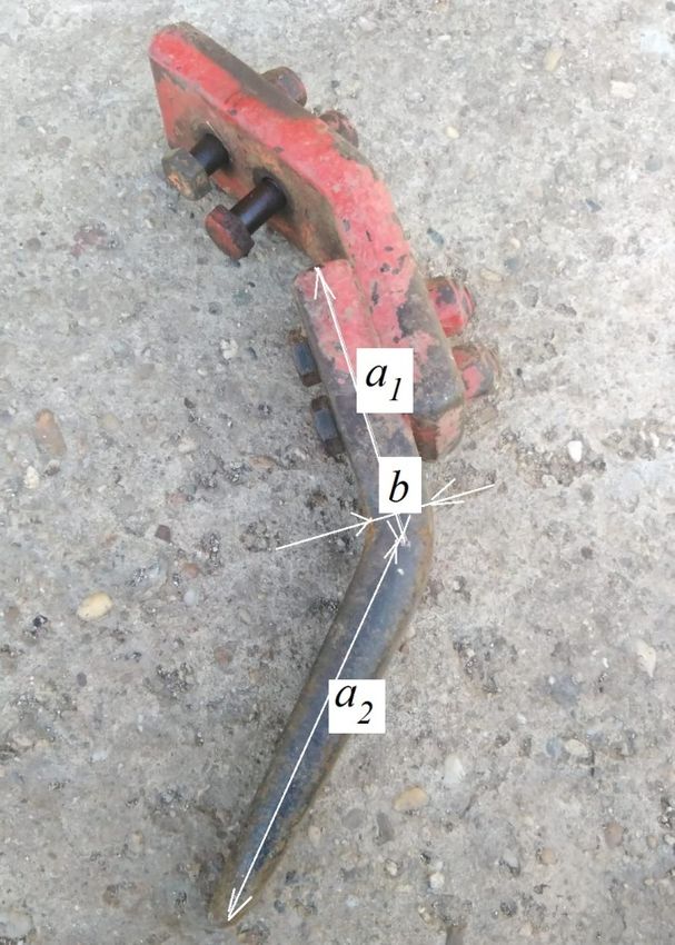
E3S Web of Conferences 286, 03023 (2021) https://doi.org/10.1051/e3sconf/202128603023
TE-RE-RD 2021
connected on the ring[2.3]. The loads of 100 N on each knife are evenly distributed along
the length of the lower segment of the knife, a length which, in this example, represents the
working depth[1.6]. The forces are oriented in the tangent direction to the circles on which
the knife points rotate, simulating the reaction of the ground on the knives when the
difference between the mechanical characteristics of the ground through which the knives
did not pass and those of the ground through which the knives passed is not taken into
account. There are also alternatives closer to reality for loading knives. Given the low speed
of movement of the aggregate, it can be hypothesized that on a portion of a quarter circle
from the tractor, the knives process hard soil, on the sides work in partially processed soil,
and behind the equipment work in already processed soil. With the help of this hypothesis,
results closer to reality are obtained. However, the hypothesis used in this article is more
covering, taking into account the harsh regime of knife operation (shocks and intense
friction).
The structural models presented in this paper are three-dimensional, combined with
finite elements of bar type and solid type. The main purpose of these mathematical models
is to estimate as close as possible to reality, the stress state of the knifes material, in the
context in which experimental validation on knives is difficult to achieve.
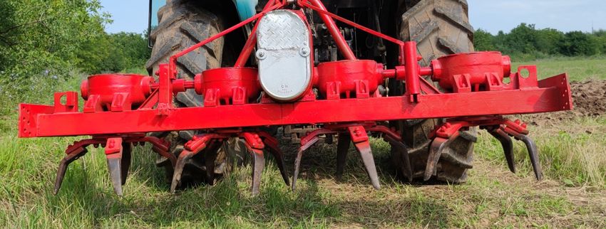
Fig. 1. Detail of the four rotors that equip the agricultural harrow with vertical rotors.
2 Materials and methods
The material analyzed in the article consists of the agricultural harrow with vertical
rotor (fig.1), formed by working organs (knives), connected to their rotation system.
The analyzed harrow has four rotors that can be equipped with two, three or 4 knives per
rotor. The dimensioning of the main dimensions used for the abstraction of the puree model
with 1D bar finite elements and for the geometric construction of the puree model with
solid finite elements (3D) is observed in fig. 4. A detail of the working element is presented
in fig. 3.
2
E3S Web of Conferences 286, 03023 (2021)                          https://doi.org/10.1051/e3sconf/202128603023
TE-RE-RD 2021

     Fig. 2. The structural model of the rotor subassembly formed by knives and a connection ring with
     the motion transmission system.

     Fig. 3 The structural model of the rotor subassembly formed by knives and a connection ring with the
     motion transmission system.
          The geometry of the mashed structural model with bar type elements, 1D, is given in
     fig. 4.
     For the structural model with 3D dimensional finite elements, the geometry is represented
     graphically in fig. 5. For the construction of the geometry, in the case of both models, we
     used values of the main dimensions defined in fig. 2 and 3: a1 = 0.15 m, a2 = 0.2 m, b =
     0.02 m, c = 0.05 m.

                                                       3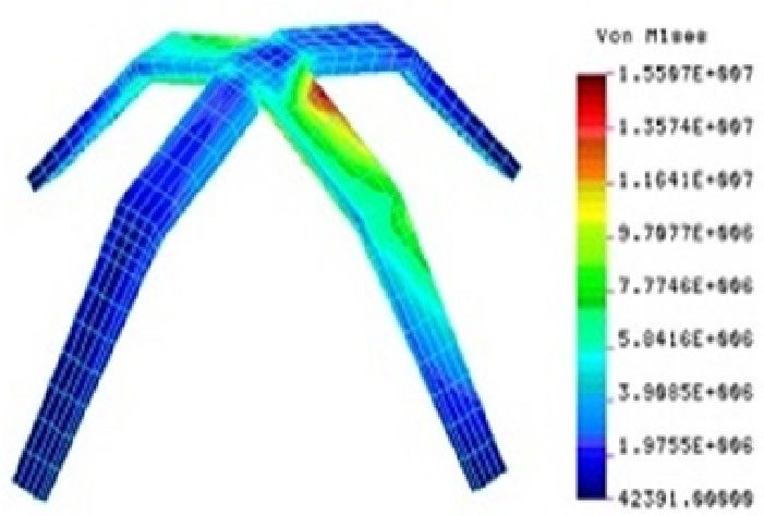
E3S Web of Conferences 286, 03023 (2021)               https://doi.org/10.1051/e3sconf/202128603023
TE-RE-RD 2021

      Fig. 4 Average dimensions for basic models

      Fig. 5 Average dimensions for basic knife

                                                   4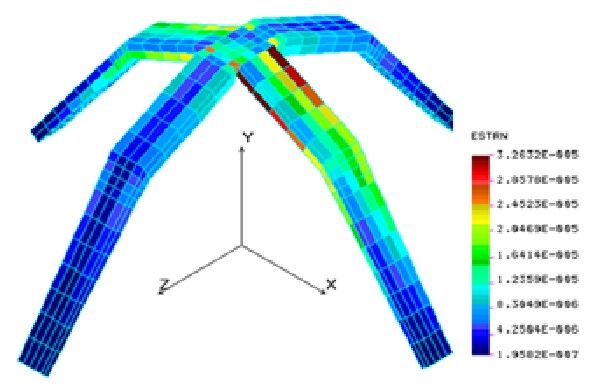
E3S Web of Conferences 286, 03023 (2021)                                 https://doi.org/10.1051/e3sconf/202128603023
TE-RE-RD 2021

      Fig. 5 Structural model of the subassembly of workpieces connected to the actuator, 3d model

      The material of the bars of the structural model of the garv rotor subassembly works
      (except for some accidents) only in the linear elastic field. Consequently, the material is
      characterized by the following three constants: the modulus of linear elasticity, E=2.1•1011
      N/m2 the transverse contraction coefficient, ν = 0.29 and the mass density, ρ = 7850 kg /
      m3. The inertial constants of the sections of the three types of bars used (ring bar, knife top
      bar and knife bottom bar) are given in table 1.

      Table 1 the inertial characteristics of the bar sections of the structural model in fig.2-3.

      Characteristic              Ring bar, circular             The upper part of the     Bar of the lower part
                                  crown profile with a           knife,      rectangular   of      the    knife,
                                  diameter of 40 mm              profile 50x20 mm          rectangular   profile
                                  and a thickness of 4                                     35x15 mm
                                  mm
      Area of the section, m2             4.521599·10-4                          0.001                   5.25·10-4
      Moment of inertia Iy,               7.415422·10-8                   2.083333·10-8               9.84375·10-9
      m4
      Moment of inertia Iz,                7.415422·10-8                  3.333333·10-8              5.359375·10-8
      m4
      Depth of section, m                             0.04                         0.05                     0.035
      Section width, m                                0.04                         0.02                     0.015

           For the 1D and 3D structural models shown in fig (3-5), the forces are applied on the
     faces of the working organs that interact frontally with the ground, and on the support of the
     structures it is done by cancelling all degrees of freedom (three translations and three
     rotations), in the upper part of the structure. The forces are applied to the faces of the
     working body that interact frontally with the ground. The tensile strength is intensely
     variable over time, so it, for static analysis, we applied an average on each organ, taking
     into account the fact that the four working organs move in uncultivated soil on a single
     already fully processed. The theoretically calculated forces have been corrected to achieve
     the total traction force and the total power consumed in experimental tests of the rotary
     agricultural harrow tractor with vertical axis rotors. In this valuable way for the 1D model,

                                                             5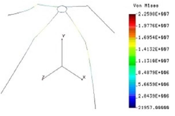
E3S Web of Conferences 286, 03023 (2021)                            https://doi.org/10.1051/e3sconf/202128603023
TE-RE-RD 2021

      they are distributed in 9 nodes on each knife, and for the 3d model on all the nodes of the
      faces exposed to the frontal presence of the ground.
            In fig.6, is represented the distribution of the reaction forces in the fixing nodes of the
      structures, located on the ring. The maximum value of 1109.2 N is reached in the bearing
      points. As it is observed the application of some pairs of strong structures as a whole, it
      leads to higher forces in the bearing points. This fact draws attention to the need for
      projects and the realization of safe mobile couplings in order not to wear them prematurely
      and / or to produce work accidents with possible very serious consequences.

      Fig.6 Reactions at the fixing points of the knives on the ring, in N

            3 Results and discussion
      The results of loading the structural model of the vertical subassembly are: the relative
      displacement resulting in the structure, having the maximum value 0.00013 mm, located at
      the free ends of the knives, the maximum equivalent tension, with the value 18.831 MPa,
      located on the knives, in the vicinity of the connection area . support ring. The maximum
      value of 1109.2 N is reached in the bearing points. As can be seen from the application of
      pairs of strong structures as a whole, it leads to higher forces at the support points.
      A result obtained using the three-dimensional model is the fundamental eigenfrequency
      with the level 121.716 Hz and the next eigenfrequency of the structures, with the value
      137.628 Hz. These natural frequencies are useful in the design calculation, but especially in
      the calculation of improving the intensity of intense vibrations that can be generated by
      resonance phenomena. When making this statement, we take into account the values that
      can reach, for example, the speed of the rotor (higher than those used in the experiments we
      performed).

                                                        6
E3S Web of Conferences 286, 03023 (2021) https://doi.org/10.1051/e3sconf/202128603023
TE-RE-RD 2021
Fig. 7 Distribution of the total strain field on the boundary of the structure analyzed in 3D model
Fig.8 Equivalent stress state (Von Mises) in the structural model, in Pa in the 1D model.
7E3S Web of Conferences 286, 03023 (2021) https://doi.org/10.1051/e3sconf/202128603023
TE-RE-RD 2021
Fig.9 Diastribution of the equivalent stress field on the boundary of the structures, in Pa in 3D model
In order to compare the results obtained by the 1D and 3D methods, the distribution
of the equivalent stress is represented in fig 8 and 9, obtaining the variant of the structural
model 1D and respectively 3D.
4.Conclusions
- the structural models proposed and solved with the help of the finite element
method, provide useful information for the activity of conception and design of the
modeled elements and subassemblies. The stresses and deformations in the analyzed
structure can be estimated and thus the safety factor can be estimated, so their resistance.
From this point of view, the analyzed structure is very correctly dimensioned, apparently
even oversized. In general, however, given the inhomogeneity of the soil, its anisotropy and
high peripheral speeds, violent shocks can occur in operation, which means an increase of
over 2.5 times the applied force, possibly in much smaller areas than in the examples.
-in the presented models you can change materials, geometry, loading to simulate
various phenomena. The model with 1D element admits the fastest change of the geometry
of the section, requiring only the change of the inertial characteristics of the cross section.
-the analyzed models can be used to diagnose in operation some vibration regimes
with resonance. The eigenfrequencies of the analyzed structure are obtained by analyzing
the spectrum of own frequencies of the elements and subassemblies of the modeled
physical structure (in our case the subassembly of working organs). In this concrete case,
the working frequencies of the rotors (17-22 Hz) are very low comparing with the first two
natural frequencies of the examined subassembly (121.716 and 137.628 Hz).
-for the structural models built in this paper, it was considered that the material of
the structures have an elastic linear behaviour. If the appearance of irreversible
deformations is studied, then, materials with nonlinear properties must be considered -
rigidity of the structure and the theoretically estimated values of the forces, used in
mathematical models, exclude the occurrence of the irreversible deformations in the
structure..
8E3S Web of Conferences 286, 03023 (2021) https://doi.org/10.1051/e3sconf/202128603023
TE-RE-RD 2021
References
1. M. Voicu, Teoria sistemelor, Editura Academiei Romane, (2008)
2. Foley, James D. (1996), "12.7 Constructive Solid Geometry", Computer Graphics:
Principles and Practice, Addison-Wesley Professional, pp. 557–558, ISBN 9780201848403
3. M. Li, Q. Zhang, H. Wang, H. Sun, J. Tong, A 3D FINITE ELEMENT SIMULATION
ANALYSIS OF THE SOIL FORCES ACTING ON A ROTARY BLADE, Transactions of
the ASABE (American Society of Agricultural and Biological Engineers) · January (2015)
4. Structural Research & Analysis corp., COSMOS/M 2.7 CAD Interface User Guide,
2007Foote R. L., The Volume Swept out by a Moving Planar Region, Mathematical
Magazine, Vol. 79, No. 4, 2006, pp. 289-297
5. Rades M., Analiza cu elemente finite, (2006)
6. Tolvaly-Rosca F., Pasztor J., Work process analysis of the machines with working
parts entrained, in seedbed preparation works, INMATEH Agricultural Engineering, vol.
58, 9:16, No. 2 / (2019)
7. Cardei P. &all, Structural analysis and materials focused on mechanics, mechatronics,
maintenance and operation of machinery for agriculture and food industry, Terra Nostra
Iasi publishing house, (2012)
8. ASABE (American Society of Agricultural and Biological Engineers, ASAE D497.7
MAR2011 Agricultural Machinery Management Data, Standard, (2011)
9You can also read