STUDY AND ANALYSIS OF CNG/LPG CONVERSION SYSTEM
←
→
Page content transcription
If your browser does not render page correctly, please read the page content below
Chapter 5

  STUDY AND ANALYSIS OF CNG/LPG CONVERSION SYSTEM

       An evaluation of global market potential for LPG and CNG Vehicles and
Alternative Fuel Conversion Equipment reveals that the number of LPG/CNG kits sold
globally was 2.9 million in 2006 and estimated that it will reach 8 million by 2012. LPG
kits will continue to dominate the market in the European Union (EU), Russia and Turkey
and other markets of the world. India and Iran accounted for 20% of global sales of CNG
kits in 2006. While aftermarket sales of LPG/CNG kits currently hold more than 85% of
total global kit sales, OEM kit sales will steadily increase to reach more than 27% of total
number of units sold by 2012. An appropriate infrastructure (i.e. sufficient number of tank
stations) along with required support from governments will accelerate the growth of
LPG and CNG as an alternative fuels [135].

       CNG and LPG conversion system stores, transfers, vapourizes (in case of LPG
system), mixes fuel with air and finally makes it ready to be combusted in the engine
cylinder.

       Mechanical conversions systems for CNG and LPG are basically identical with
some exceptions. Storage tanks are different for LPG system. A vapourizer is necessary
in LPG conversion systems to vapourize LPG to a low pressure vapour. In CNG
conversion system, a high pressure regulator (HPR) is necessary to reduce high pressure
of natural gas (200 bar) to a low pressure. While in LPG system HPR is not required due
to low pressure in LPG storage tank. Electronic conversion system supports are similar
for both CNG and LPG system.

       The specifications for LPG as vehicular fuel is governed by an Indian Standard
(IS 14861:2000). This fuel is called Auto LPG. Many RTO-recognized agencies in all
major cities offer conversion kits. There are number of kits approved by government
institutes for various brands and models of vehicles. Italy has the highest number of LPG-
driven vehicles, and it is the pioneer manufacturer of LPG systems.

       The conversion kit for LPG mainly consists of storage tank, vapourizer, solenoid
for Gasoline and LPG and changeover switch with tank-level indicator. The capacity of
storage tank is 40 to 60 liters and it is permanently fixed to the vehicle chassis. The tank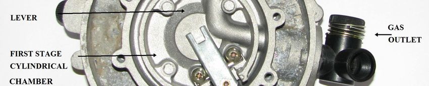
112
  Chapter 5 - STUDY AND ANALYSIS OF CNG/LPG CONVERSION SYSTEM
________________________________________________________________________

is designed to withstand pressure build-up and is sufficiently crash-proof and bullet-proof.
The tank must be hydro-tested every year and certificate of latest testing must be
displayed near LPG filling valve on the vehicle. A multi-function valve on the tank
facilitates filling and limits to 80% of its volumetric capacity for safety purpose. The
valve also has a safety relief valve, fusible plug, shut-off valve and level indicator.

5.1 Working Principle of CNG fuel system

       CNG is stored on-board the vehicle under pressure in the fuel storage cylinder to a
maximum pressure of approximately 200 bar. When the valve in the fuel storage cylinder
is opened, CNG at cylinder pressure flows through the excess flow valve and to the T
connector. From T connector, CNG at cylinder pressure flows to the three way valve. A
high pressure gauge is mounted on the cylinder side of three way valve to show cylinder
pressure. From three way valve it flows to the high pressure filter. From high pressure
filter, CNG at cylinder pressure flows to the high pressure regulator (HPR). The HPR
reduces the pressure of the CNG in one stage from cylinder pressure to 14 bar.

       From HPR, CNG flows through gas shut off valve (GSOV), which is normally
closed. It requires an electric signal from air-fuel ratio (AFR) controller to open. This is
desirable safety feature, if the engine stops or is turned off, fuel flow automatically stops.

       From GSOV, CNG flows to Low Pressure Regulator (LPR). As CNG flows
through LPR, pressure is reduced in two stages from HPR output pressure to slightly less
than atmospheric pressure, it is very important that outlet pressure of regulator and inlet
pressure of air fuel mixer be matched properly.

       From LPR, NG flows to air fuel mixer, the fuel passage is normally closed. A
vacuum signal from the engine cranking or running is required to draw fuel from fuel
outlet. This is a desirable safety feature, if the engine stops or is turned off, fuel flow
automatically stops. When mixer receives desired vacuum signal from the engine, it
draws metered amount of NG from pressure regulator and blends it with air at proper
stoichiometric ratio to achieve peak engine performance over complete operating range.

       Overview of basic CNG and LPG conversion system are shown in fig. 5.1 and fig.
5.2 respectively. The main components of CNG/LPG conversion system are shown in fig.
5.3 and LPR / Vapourizer body is shown in fig. 5.4.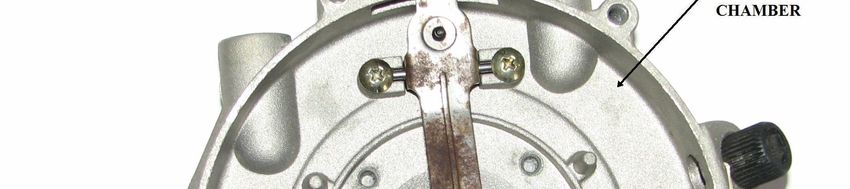
113
  Chapter 5 - STUDY AND ANALYSIS OF CNG/LPG CONVERSION SYSTEM
________________________________________________________________________

             Fig. 5.1. Overview of basic CNG conversion system [136].

             Fig. 5.2. Overview of basic LPG conversion system[136].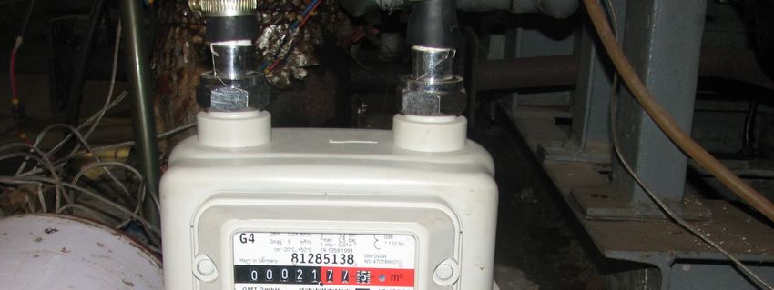
114
Chapter 5 - STUDY AND ANALYSIS OF CNG/LPG CONVERSION SYSTEM
________________________________________________________________________
Fig. 5.3. Components of CNG/LPG conversion system.
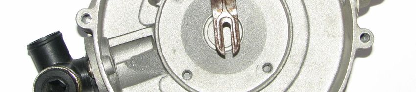
Fig. 5.4. Low Pressure Regulator (LPR)/Vapourizer.
115
Chapter 5 - STUDY AND ANALYSIS OF CNG/LPG CONVERSION SYSTEM
________________________________________________________________________
The fuel system consists of following major parts:
Unidirectional Receptacle Valve
Excess flow check valve
Burst Disc
Three way valve
High pressure gauge with indicator
High pressure filter and low pressure filter
High pressure regulator (HPR)
Low pressure regulator (LPR)
Gas shut off valve (GSOV)
Air fuel ratio (AFR) solenoid
Over speed controller
Air-fuel mixer
Gaseous Fuel Tank
AFR controller and engine speed governor
Injector cable emulator (in case vehicle is multipoint fuel injection)
Change over switch
Hoses and fittings
Pipes
Exhaust gas oxygen (EGO) sensor
Catalytic converter
Unidirectional Receptacle Valve
It is one way valve used for refuelling as shown in fig 5.5. It is to be ensured that
cap is closed after filling is done. Valve has a cut off switch as a safety device which cuts
off the ignition circuit when the cap is not fitted.
The system consists of one valve for filling tank and other for delivery to the
intake manifold. It is a non-return valve, thus filling of tank and delivery to the engine is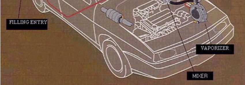
116
  Chapter 5 - STUDY AND ANALYSIS OF CNG/LPG CONVERSION SYSTEM
________________________________________________________________________

accomplished through same system and no separate valves are mounted. It is very tightly
fitted on the tank using bolts and rubber packing to avoid minor leakage. For filling gas
from gas filling station, filler valve is mounted on it. From gas station, filling equipment
is fitted on filler valve and gas is filling up into the tank at high pressure [88].

                          Fig. 5.5. Unidirectional Receptacle Valve.

The basic features are stated below:

    1. In case of an accident or leakage, the automatic operation of solenoid is shut off
        gas supply.

    2. It has manual shut off lever to control the operation.
    3. There is a provision of fusible plug which melts down if temperature increases
        and hence the gas releases.
    4. There is a pressure relief valve which operates when gas pressure in tank exceeds
        the limiting pressure.
Excess flow check valve

        This valve normally remains in open position and it closes automatically in the
direction of flow for which it is designed, when a predetermined flow limit is exceeded.
Excess flow valve checks for excess flow of gas in incident of any leakage. It is a safety
device assembled with T connector.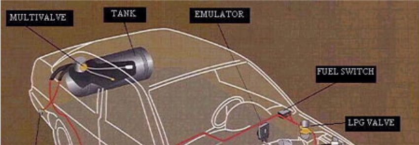
117
  Chapter 5 - STUDY AND ANALYSIS OF CNG/LPG CONVERSION SYSTEM
________________________________________________________________________

Burst disc

        A fusible disc is a safety device which comes into action when pressure in the
cylinders exceeds 300-330 bar. The fusible disc fuses at pressure more than 300-330 bar
and helps venting high pressure gas in the cylinder to escape in atmosphere through
certain vent hoses.

Change Over Switch

        The switch is wired into the vehicle’s electrical system, allowing for functioning
fuel gauge, as well as proper automatic switching between CNG/LPG and gasoline (along
with a dashboard-mounted manual switch). There must be connections to the engine’s
electronic control unit (ECU) so that the engine controller can adjust for different fuel
settings.

        Vehicles      with   an   electronic injection   system   will   probably   need    an
electronic emulator. When the engine is operating on CNG/LPG fuels, the fuel injectors
will not send any information to other sensors in engine - this will light up the “check
engine” light and give incorrect diagnostic readings. The emulator fakes the signals so the
ECU can operate properly.

                             Fig. 5.6. Dashboard fuel switch/gauge.

High Pressure Filter

        It filters CNG before it being sent to the system along with all kinds of suspended
dust particles and oil globules from entering into HPR. It is to be replaced within twelve
months of use. For maintenance procedure, close all cylinder valves and start the engine,
continue till the engine stops on its own. Ensure there is no gas in the system. Remove the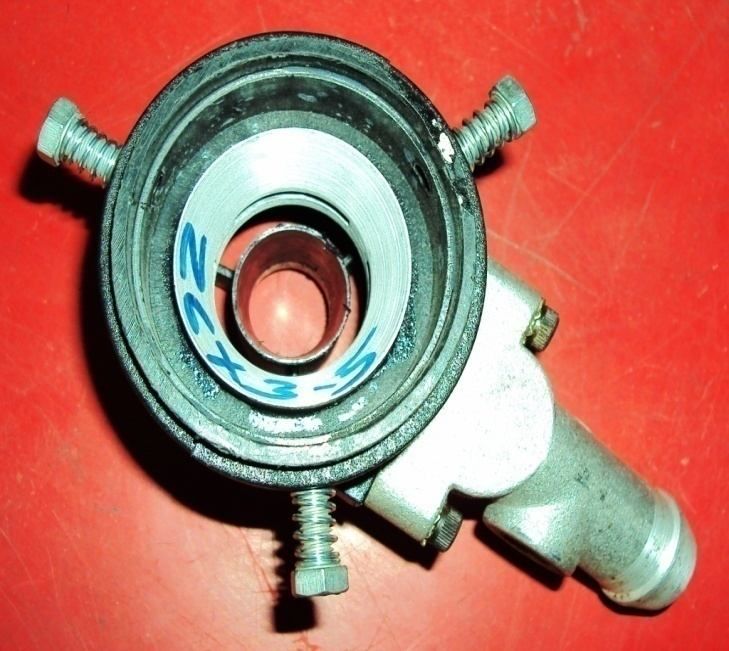
118
  Chapter 5 - STUDY AND ANALYSIS OF CNG/LPG CONVERSION SYSTEM
________________________________________________________________________

drain plug at the bottom of the filter assembly. Drain all oil, moisture, etc. Refit the drain
plug and check for leakage [127].

First stage regulator / HPR

        HPR is a single stage regulator. It is mounted between high pressure filter and gas
shut off valve. It is not field serviceable. The primary function of HPR is to accept fuel at
storage container pressure up to 200 bar, and reduce it to an outlet pressure of 14 bar.
This is necessary because of high storage pressure of CNG. It is heated by engine coolant
to eliminate freezing of any moisture during pressure drop. It is equipped with safety
relief valve, which will release pressure if it exceeds normal limit. This protects low
pressure components downstream. The safety relief valve is actuated by pressure only and
no temperature actuation is provided. The pressure relief valve will reset after opening
and reducing the pressure. It is not to be replaced after operation. Since HPR is heated by
engine coolant, it must be mounted near the radiator to avoid air being trapped into
regulator.

        Normally, HPR is set at the manufacturing end and should not be adjusted in the
field. Improper installation may damage surroundings. For maintenance purpose, for
every 50000 kms running of vehicle, HPR should be removed and check for output
                                        [127]
pressure at authorized service centre       . If output pressure is found to be more than 14
bar, it should be replaced with a new one. Also it should be check for any leakage after
installation.

Second stage regulator / LPR

        The function of second stage regulator is to reduce pressure of gas from 14 bar to
0.7 bar absolute, which is slightly below atmospheric pressure.

        LPR is reducing gas pressure, allowing a regular flow of gas every time the engine
requires. It is equipped with two natural gas reduction stages that allow stability at high
pressure solenoid valve upstream from the first stage. The absorption of heat taken from
parts of regulator, heated with liquid of engine cooling circuit, prevents gas from freezing
during fall in pressure.

        The flow of gas necessary for engine idling is obtained through main gas pipe due
to vacuum generated by engine. It includes an electronic starting device with a built-in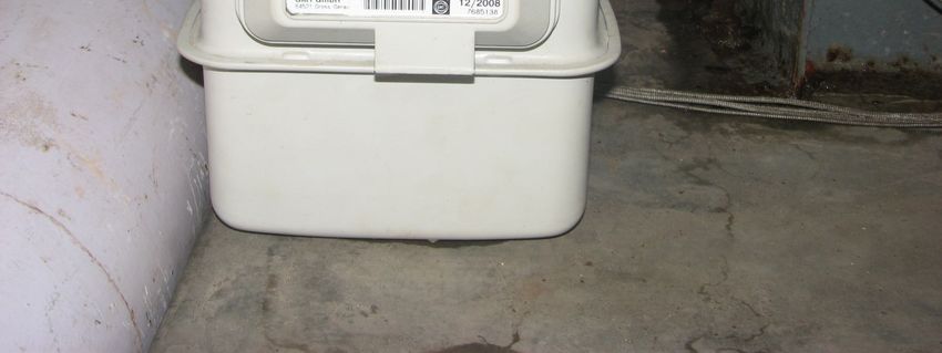
119
  Chapter 5 - STUDY AND ANALYSIS OF CNG/LPG CONVERSION SYSTEM
________________________________________________________________________

safety system that trips and shuts off gas solenoid valve if engine is switched off or even
stalls.

          After receiving an electric signal from air-fuel ratio (AFR) controller, GSOV
opens and CNG flows to inlet port of LPR. As CNG flows through LPR, the pressure is
reduced in two stages. In first stage gas flows through inlet union through duct to the first
stage valve and enters into the first stage chamber. Here pressure is reduced from 14 bar
to 3” to 6” of water column (wc), which is equivalent to 0.00747 bar to 0.015 bar. The
pressure of gas on the walls of this chamber expands the first stage diaphragm by
overcoming the resistance of calibrated spring. This first stage diaphragm is connected to
lever fulcrum which acts on the first stage valve. Due to open-close movement,
diaphragm creates a pressure balance. The pressure in this stage is kept constant by force
of spring that presses downwards due to effect of pressure under diaphragm, which
pushes it upwards. This way under diaphragm, gas enters into first stage chamber and
passes to the second stage. Practically, gas enters into first stage and gas pressure
generates a force that pushes first stage diaphragm up. The diaphragm, though, has a
spring above it that pushes it down with a counter-force (spring force) corresponding to
pressure generated in this stage. The generation of two counteracting forces makes the
lever to close gas inlet orifice.

          The second stage which is also known as low pressure stage consists of a rubber
diaphragm attached to the steel lever by an aluminum cap. This stage actually
communicates with the engine through gas outlet pipe, leading to mixer and thus subject
to negative pressure generated in mixer when throttle valve is opened.

          Practically when acceleration takes place, a force is created that pushes second
stage diaphragm inwards into reducer, thus allowing gas to pass through orifice to second
stage, from where the same quantity that comes out finally is sucked out of reducer into
mixer, and then fed into the engine. The sensitivity of spring that holds up lever is set by
adjuster on the side of reducer.

          The vacuum generated by engine produces an axial movement of second stage
diaphragm which being connected to lever and opens second stage valve, permitting the
gas to reach second stage chamber through orifice and finally to the engine by means of
special pipes. Valve opening, closing and lever seal is obtained due to calibrated spring.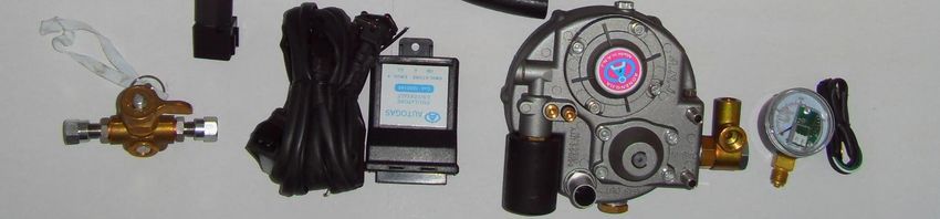
120
  Chapter 5 - STUDY AND ANALYSIS OF CNG/LPG CONVERSION SYSTEM
________________________________________________________________________

This spring acts on the lever by means of pin that ensures seal when the engine is turned
off. The device is made up by solenoid valve controlled by an electronic device that gives
current only when engine starts. Once the engine starts, device releases lever of second
stage and permits gas to outgo valve of second stage to reach the engine. If engine do not
starts, coil de-energizes the core and spring exerts again pressure on lever which further
closes the gas flow. This happens also if the engine should stop for any reason. When
current is supplied, the electronic device activates coil for a predetermined gap which
releases lever of second stage and supplies a sufficient quantity of gas to start engine.

       To maintain the stoichiometric ratio, regulator needs to change position of second
stage diaphragm. The position of diaphragm is depends on atmospheric pressure and
engine vacuum, which is connected to LPR control port through A/F solenoid. In normal
condition it senses the atmospheric pressure and delivers gas at higher side. After
receiving signal from A/F solenoid, it will connect engine vacuum to diaphragm through
LPR control port. A/F solenoid will reduce gas pressure as require and maintain
stoichiometric ratio.

Air Fuel Solenoid

       Normally it connects atmospheric pressure to LPR control port. After getting
signal from A/F controller, it connects mixer vacuum to LPR control port. Top port is
connected to mixer with hose, center port is connected to LPR control port with rubber
tube & bottom port is left open to atmosphere.

       A solenoid valve is an electro-mechanical valve which is controlled by electric
current through a solenoid coil. Solenoid valve may have two or more ports. In case of
two-port valve, the flow is switched on or off. In case of three-port valve, the outflow is
switched between two outlet ports. Multiple solenoid valves can be placed together on a
manifold. Solenoid valves are the most frequently used control elements in fluidics. They
are used to shut off, release, distribute or mix fluids. They are found in many application
areas. Solenoids offer fast and safe switching, high reliability, long service life, good
medium compatibility of materials used, low control power and compact design. A
solenoid valve must be installed on fuel line in between tank and regulator. This valve
cuts the flow of gas when vehicle is running on gasoline when engine is shut off. It also
has a filter built in, which removes any dirt in the fuel.
121
Chapter 5 - STUDY AND ANALYSIS OF CNG/LPG CONVERSION SYSTEM
________________________________________________________________________
The solenoid converts electrical energy into mechanical energy which, in turn,
opens or closes the valve mechanically. A direct acting valve has only a small flow
circuit, shown in section E in fig. 5.7. Solenoid valves may use metal or rubber seals and
may also have electrical interfaces to allow easy control. A spring may be used to hold
the valve opened or closed when it is not activated.
Fig. 5.7. Cross- section of solenoid valve.
A-Input side, B-diaphragm, C-Pressure chamber, D-Pressure relief conduit, E-solenoid,
F-output side.
As shown in fig.5.7 valve is in closed position initially. The fluid under pressure
enters at ‘A’ and a weak spring pushes elastic diaphragm ‘B’ to downward side. The
diaphragm has a pinhole through its centre which allows a very small amount of fluid to
flow through it. This fluid fills the cavity on other side of diaphragm so that pressure is
equal on both sides of diaphragm. While pressure is same on both sides of diaphragm, the
force is greater on upper side which forces the valve in closed position. The small
conduit ‘D’ is blocked by a pin which is armature of solenoid ‘E’ and pushed down by a122
Chapter 5 - STUDY AND ANALYSIS OF CNG/LPG CONVERSION SYSTEM
________________________________________________________________________
spring. If solenoid is activated by drawing pin upwards through magnetic force
from solenoid current, fluid in chamber ‘C’ will flow through conduit ‘D’ to output side
of the valve. The pressure in chamber ‘C’ will drop and incoming pressure will lift the
diaphragm thus opening main valve. Fluid now flows directly from ‘A’ to ‘F’. When
solenoid is actuated and the conduit ‘D’ is closed, the spring needs very little force to
push the diaphragm down and the main valve closes. In practice there is often no separate
spring, the elastomeric diaphragm is moulded so that it functions as its own spring,
preferring to be in the closed shape.
Over Speed Controller
It is used to govern engine speed, when engine rpm reaches more than rated speed,
it gives electric signal to over speed solenoid to reduce fuel flow by 80%. If engine speed
is increased to maximum operating range, it cuts the supply of shut off valve to govern
engine speed.
Gas Injectors:
These are used for conversion systems, where similar to multipoint fuel injection
system, individual gas injectors control gas flow into each cylinder further controlled by a
processor unit.
Emulator/Simulator:
The electronic fuel injection (EFI) system is generally kept non-functional at
CNG/LPG operation. In some engines feedback signals from the fuel injectors fed back to
the electronic control units (ECU). Under CNG operation the emulator simulates dummy
feedback signals to the ECU, maintaining its normal operation with gasoline. This
component may not be necessary for all models of EFI engines.
Fig. 5.8 Emulator.123
Chapter 5 - STUDY AND ANALYSIS OF CNG/LPG CONVERSION SYSTEM
________________________________________________________________________
Exhaust gas Oxygen (EGO) Sensor and Speed sensors
Often these are required in close-loop gas flow-control CNG conversion systems.
After getting heat from exhaust gases, it counts the amount of oxygen passing through
exhaust gas and gives the signal to air-fuel controller in DC voltage form.
Catalytic Converter
It is located between silencer muffler and exhaust manifold. Three-way catalytic
converter is installed in exhaust pipe, which controls out going exhaust emission to
minimum levels. The unit consists of ceramic substrate of honey-comb structure. This is
coated with catalyst material consisting of precious metals such as platinum and rhodium.
This catalyst material enhances the rate of chemical reactions. Following chemical
reaction takes place while exhaust gas passes through the catalytic converter.
2 NO2 N 2 2O2 (5.1)
2 HC 3O H 2O 2CO2 (5.2)
CO O CO2 (5.3)
The reduction catalyst is the first stage of catalytic converter. It uses platinum and
rhodium to reduce NOx emissions. When NO and NO2 molecule contacts catalyst, it
separates out nitrogen atom from its molecule and holds on to it, release oxygen in the
form of O2. The nitrogen atoms bond with other nitrogen atoms that are also stuck to the
catalyst, forming N2.
The oxidation catalyst (platinum and palladium) is second stage of catalytic
converter. It oxidizes the unburned hydrocarbons and carbon monoxide. This catalyst aids
the reaction of CO and hydrocarbons with remaining oxygen in exhaust gas [137].
Gas Flow Meter
The compact residential gas flow meter (fig.5.9) is designed to measure volumes
of natural gas, LPG and all non-corrosive gases very accurately. During the preliminary
test controls on the sonic nozzle test benches, all meters are tested at Qmin, 0.2 times Qmax
and Qmax [138].124
Chapter 5 - STUDY AND ANALYSIS OF CNG/LPG CONVERSION SYSTEM
________________________________________________________________________
Fig. 5.9. Gas flow meter.
Specifications:
Make : Germany
Gas Type : Natural gas, LPG and all non-corrosive gases
Cyclic Volume : 1.2 dm3
Operating Temperature : -25º C to + 55º C
Storage Temperature : -30º C to + 70º C
Maximum Operating Pressure: 0.5 bar for steel version
Measuring Range : G4
: Qmin = 0.04 m3/hr
: Qmax = 6 m3/hr
Pulse Generator : Standard 0.01 m3/pulse
Range : G1.6, G2.5, G4
Operating Principle
It is positive displacement diaphragm type gas flow meter with a twin chamber
measuring unit. The twin chambers are fitted with flexible and gas-tight diaphragm which
is actuated by the differential between inlet and outlet pressure. The gas enters one side of
the diaphragm pan while on the other side it comes out through a separate port on the
valve. When one side is full, the rotating mono-valve moves on to next position, allowing
the gas to fill empty side. A transmission gear and mechanical coupling or stuffing box125
Chapter 5 - STUDY AND ANALYSIS OF CNG/LPG CONVERSION SYSTEM
________________________________________________________________________
transfers the reciprocating motion to mechanical retrofitted index [139]. The measuring unit
is housed in a robust gas-tight casing.
Construction
Casing
With its casing in steel, high protection against corrosion is ensured by 500 hours
salt fog spray test resistant cataphoresis treatment. The extreme strength of case joint is
achieved by rolling the belt and compressing the flanges into contact with a sealant
applied between the faces, thus forming gas-tight joint.
Measuring Unit
The achievement of fixed stroke mechanism is the result of precision and high
quality automation. It eliminates the need for an adjustable tangent. The long life
synthetic diaphragms coupled to well-proven movement design combine to give excellent
stability and accuracy during whole life of meter.
All materials have been selected for their superior resistance to chemicals and gas.
A back run stop prevents the meter from running backwards in case of tempering.
AIR FUEL MIXER:
After reducing pressure of the gaseous fuel (CNG/LPG) in low pressure
regulator/vapourizer, gas is mixed with air for combustion. This process is called mixing
and it is done outside the combustion chamber. The device used to mix gaseous fuel with
air is called MIXER.126
Chapter 5 - STUDY AND ANALYSIS OF CNG/LPG CONVERSION SYSTEM
________________________________________________________________________
Fig.5.10. Cross section of a mixer.
As seen in the fig. 5.10, the section of mixer is like a converging-diverging nozzle.
The section at centre is called throat. When the accelerator is pressed, suction is created in
the engine and hence air is drawn at a greater rate. The air filter sucks air from
atmosphere. As shown in fig. 5.10, there is a converging section of nozzle, through which
air enters from air filter due to engine suction. The velocity of air increases in converging
section and its pressure drops. At the throat section of mixer, velocity is higher and
pressure is at its lowest value below atmospheric.
The gaseous fuel in the vapourizer is at nearly atmospheric pressure due to
pressure difference and velocity difference, thus fuel is entrained in the mixer. In general,
three inlet ports are provided on the periphery of the throat section at 120º. Fuel enters
into the mixer at throat section and proper mixing with air takes place.
In mixer, air-fuel mixture again expands in diverging section and its velocity
drops and pressure rise is negligible. Then mixture enters the engine combustion
chamber. Generally different types of engines have different geometry of mixers. The
flow of air and fuel is again controlled by solenoid valve. Fig. 5.11 shows air-fuel mixer
of maruti make, 800 cc engine.127
Chapter 5 - STUDY AND ANALYSIS OF CNG/LPG CONVERSION SYSTEM
________________________________________________________________________
Fig. 5.11. Air-Fuel Mixer.
For MARUTI 800 engine, the standard dimensions of an air-fuel mixture are as follows:
Material - alluminium alloy
Diameter (throat): 26 mm
Slot Width : 3.5 mm, 3 slots at an angle of 120o at throat periphery
Diaphragm:
Diaphragm is a specially designed rubber coated fabric of specific engineering
designed layout fitted with metal, rubber or/and plastic parts. It is used where
hermetically sealing & flexible working is required by dividing two volumes of
interchanging dimensions, interchanging pressures usually of different media.
Fig. 5.12. Diaphragm of 1st stage and 2nd stage vapourizer/LPR.128
Chapter 5 - STUDY AND ANALYSIS OF CNG/LPG CONVERSION SYSTEM
________________________________________________________________________
The diaphragm for LPG/CNG Auto conversion kits are made from ozone resistant
nitrile rubber reinforced with Nylon for strength and held with a special gasket sheet
meant for high temperature and oil resistance. Diaphragm thickness varying between 0.2
mm to 0.3 mm reinforced with 0.1 mm thick Nylon sheet with a breaking strength of 125
kg/sq cm.
Fuel Tank/Cylinder:
CNG cylinder:
CNG cylinders can be made of steel, aluminium or composite material. Light
weight composite (fibre-wrapped thin metal “ISO 11439 CNG-3”/ fibre-wrapped plastic
“ISO 11439 CNG-4”) cylinders are especially beneficial for vehicular use because they
offer significant weight reduction compared to steel and aluminium cylinders which leads
to lower fuel consumption.
CNG storage tanks are available in different shapes and sizes depending upon the
application. The main two types of storage tanks commonly used are cylindrical tank and
toroidal tank.
Since CNG is a gaseous fuel, storage capacity for CNG in a vehicle is
comparatively less than that of Gasoline. The quantity of CNG filled by the dispenser
during refuelling also depends upon pressure at the dispensing station. At maximum
permitted filling pressure (200 bar), an amount of 8/9/10 kg CNG is stored in 40/50/60
liters size cylinders respectively which is equivalent to approximately 11.2/12.5/14 liters
of Gasoline equivalent. However the gas quantity depends on ambient conditions and
actual fill pressure.
The quantity of the CNG in the cylinder usually depends on two factors pressure
and temperature. But there is a significant effect of compressibility factor on the quantity
of CNG in cylinder.129
Chapter 5 - STUDY AND ANALYSIS OF CNG/LPG CONVERSION SYSTEM
________________________________________________________________________
Fig. 5.13 Cylindrical Tank for CNG.
Fig. 5.14 Toroidal tank for CNG.
The compressibility factor z is a correction factor to the Boyle Gay-Lussac Law
P V z R T (5.4)
The z factor is depending on gas composition and temperature, e.g. at 250 bar and
20° C, z = 1.45, at 150 bar and 20° C, z =1.18 [3].
Vapour withdrawal low pressure LPG cylinder:
Vapour withdrawal LPG fuel tanks are designed for fuel systems that require fuel
to be supplied to pressure regulator in vapour form. Since propane expands 270 times as it
changes from a liquid to a vapour, far less fuel can flow through fuel line to engine. As a
result, vapour withdrawal systems are used primarily on small displacement engines.130
Chapter 5 - STUDY AND ANALYSIS OF CNG/LPG CONVERSION SYSTEM
________________________________________________________________________
Inside the fuel tank is a dip tube attached to a vapour outlet port. This dip tube is
designed so that open end is positioned in vapour space above 80% liquid level of fuel
tank when tank is properly positioned horizontally or vertically. It is very important that
fuel tank should not be filled more than 80% of total water capacity with LPG. Over-
filling and/or incorrect positioning of the fuel tank may allow liquid propane to enter the
vapour fuel system through the vapour outlet port of tank, causing fuel system to
malfunction and frost formation.
On vapour withdrawal fuel systems, propane stored as liquid in fuel tank, is
allowed to vapourize in the tank before entering fuel system. Since propane absorbs heat
when it vapourizes, the surface area of fuel tank must be capable of supplying enough
heat from the surrounding air to support vapourization process. If the surface area of fuel
tank is not large enough to support vapourization process, fuel pressure will drop and
reduction of engine power output may result. Frost forming on outside of fuel tank is an
indication that the surface area of fuel tank is not large enough to support rate of
vapourization.
Liquid withdrawal low pressure LPG cylinder:
Liquid withdrawal LPG fuel tanks are designed for fuel systems that require fuel
to be supplied to the pressure regulator in liquid form. Inside the fuel tank is a dip tube
attached to a liquid outlet port. This dip tube is designed so that ‘open end’ reaches the
bottom of fuel tank when tank is positioned properly. Incorrect positioning of the fuel
tank may allow propane vapour to enter liquid outlet port of tank. A lack of engine power
output and/or frost on fuel tank is an indication that the tank is not positioned properly.
LPG storage tanks are available in torpedo or donut shape. Torpedo tanks
generally have more capacity, but will take more space in vehicle. Donut tanks are
designed to fit in the spare wheel space of vehicle. In vehicles having large empty space,
multiple tanks can be used to increase fuel storage capacity.
Generally the gas filled in tank is lesser than the full capacity for safety purpose.
In case of any accident or collision, the tank may get deformed and there are chances of
leakage of gas in the compartment which can lead to dangerous explosion. For safety
purpose an extra pipe is kept in the multi function valve. This is mainly for venting out131
Chapter 5 - STUDY AND ANALYSIS OF CNG/LPG CONVERSION SYSTEM
________________________________________________________________________
the excess gas. If while filling or due to any reason, the gas leaks out, this pipe guides the
gas out of the vehicle compartment.
Vapourizer converts the liquid propane to a gas. The primary heat source for this
vapourization is engine-jacket water which flows through specially designed water
jackets cast into vapourizer body. It is necessary that propane fuel systems draw from
bottom of the tank rather than the top. If engine feed were drawn from gas phase, heavier
and higher boiling components in LPG would gradually become concentrated in liquid
phase creating a liquid mass with low vapour pressure and high freezing point. This liquid
would create various problems in the feel feed system. Therefore, LPG systems draw
from the bottom of tank and send liquid through a vapourizer which is heated by engine
coolant.
Fig. 5.15 Donut tank and torpedo tank for LPG.
LPG fuel tank is installed, along with a refuelling port, fuel lines and pressure
safety valves. A filter “fuel lock” removes particles that may be present in propane. LPG
tanks are constructed of heavy gauge steel, in compliance with Boiler and Pressure Vessel
Code of American Society of Mechanical Engineers (ASME) to withstand a pressure of
70 bar. Normal working pressures of tanks vary with ambient temperature and quantity of
fuel in tank. LPG systems limit the liquid level to 80% of total tank volume by a stop fill
valve. Common operating pressures are in the range of 9 to 12 bar. Tanks are equipped
with pressure relief valves that will release fuel vapour to the atmosphere to prevent tank
explosion under abnormally high pressure conditions.
High Pressure gauge:
It indicates gas pressure in the tank. It is mounted on unidirectional receptacle
valve.132
Chapter 5 - STUDY AND ANALYSIS OF CNG/LPG CONVERSION SYSTEM
________________________________________________________________________
Timing Advance Processor (TAP):
Timing signal processor is used in CNG/LPG vehicles. It sends specific signals to
ECU of vehicle and as a result advances the spark timing. This results in good pickup and
mileage on such alternate fuels. Timing Advance Processor is used in manual
transmission vehicles.
Setting:
IDLE SETTING LED ADVANCE
Min Max Min Max
Fig. 5.16. Working of timing advance processor [140].
Steps:
1. Press Throttle for advancing timing.
2. Set Idle Setting preset till LED glows.
3. Adjust Advance port till satisfactory result.
4. Condition 1: If Advance Port at minimum side means there is no advance.
5. Condition 2: If LED is not glow means there is no advance.
6. Condition 3: If there is LED indication, increase Idle Setting preset to Maximum
side.
Wiring Details:
1. Green: Gas Solenoid
2. Black: Battery Negative
3. White/Violet: TPS
4. Grey: Sensor Side
5. White: ECU side133
Chapter 5 - STUDY AND ANALYSIS OF CNG/LPG CONVERSION SYSTEM
________________________________________________________________________
This unit allows optional spark advances (e.g. 6, 9, 12, 15º BTDC), generally
during accelerating conditions. The processor modifies the spark advance signal to the
electronic ignition system accordingly. Use of this improves peak power and acceleration
performance of vehicle running on CNG, while retaining the performance with gasoline.
5.2 Design of a Lever of LPR
This lever is used to maintain constant pressure inside 1st stage chamber of LPR.
When the gas cylinder inlet valve is open, CNG released at maximum pressure of 200 bar
which is reduced at 14 bar through HPR mounted on the CNG cylinder. CNG at
maximum pressure of 14 bar enters through the valve of 1st stage chamber of LPR. The
details of components of LPR/vapourizor are shown in fig.5.17 and fig.5.18.
Straight lever with parallel forces acting in the same plane is considered. F is a
fulcrum about which the lever is capable of turning. For this lever, fulcrum is in between
the load (gas force, W) and effort (spring force, P). The perpendicular distance between
the load point and fulcrum (AO= l1) is known as load arm, and perpendicular distance
between the effort point and fulcrum (OB = l2) is known as effort arm.
According to the principle of moment,
W l1 P l2 or
W l2
(5.5)
P l1
W l2
i.e. Mechanical Advantage, M.A. =
P l1
The ratio of the effort arm to the load arm, i.e. l2/ l1 is called leverage.134
Chapter 5 - STUDY AND ANALYSIS OF CNG/LPG CONVERSION SYSTEM
________________________________________________________________________
Fig.5.17 Components of Low pressure regulator/Vapourizor-1
Fig. 5.18 Components of Low pressure regulator/Vapourizor-2135
Chapter 5 - STUDY AND ANALYSIS OF CNG/LPG CONVERSION SYSTEM
________________________________________________________________________
The valve rests over valve seat which is secured to casing fixed at the inlet of 1st
stage chamber of LPR. The location of spring and its distance from fulcrum are so
adjusted that the gas pressure acting upward on valve exceeds normal limit, it lifts the
valve and lever with its spring force. The gas enters inside the 1st stage chamber until
pressure increases up to required limit to close the valve. The pressure inside the 1st
chamber decreases when the gas flows through the 2nd stage chamber to engine intake
manifold (i.e. when engine starts), the spring force compresses the end of lever on
downward side and valve seat open and thus high pressure gas enters into the 1st stage
chamber through valve. The valve is held on its seat against upward gas pressure which
must be equal to spring force i.e. when the valve is closed.
A O B
W F
Fig. 5.19 Free body diagram of a lever of LPR.
As the gas inlet pressure from HPR mounted on CNG cylinder is 14 bar,
We have p1 = 14 bar = 1.4 N/mm2
Let us assume diameter of orifice through which gas enters into 1st stage chamber is 5
mm,
The maximum gas load (W), at which the valve opens out, is given by,
2
W d1 p1 (5.6)
4
Where, d1 = diameter of orifice = 5 mm
p1 = Gas pressure at valve inlet of 1st stage chamber = 1.4 N/mm2
W 5 2 1. 4
4
= 27.48 N
30 N136
Chapter 5 - STUDY AND ANALYSIS OF CNG/LPG CONVERSION SYSTEM
________________________________________________________________________
If a large load is to be lifted by a small effort, then effort arm should be much greater than
the load arm.
Let us assume l2 3 l1 (5.7)
So
W l2
M . A. 3
P l1
OB
Leverage 3
OA
For valve seat to be closed, for lever AOB, take moment @ O,
W OA F OB (5.8)
Where F = spring force required,
AO = l1 = load arm and
OB = l2 = effort arm
30
F
3
= 10 N
To facilitate lever inside casing of pressure regulator assume l1 = 8 mm,
l2
As, 3,
l1
l2
3,
8
l2 24 mm.
5.3 Design of 1st stage cylindrical chamber of LPR
Pressure of gas filled inside the 1st stage chamber = p2
To find out dimensions of cylindrical geometry of casing of 1st stage chamber,
p1 v1 p2 v2 (5.9)137
Chapter 5 - STUDY AND ANALYSIS OF CNG/LPG CONVERSION SYSTEM
________________________________________________________________________
Where, v1 = volume of valve chamber in mm3,
v2 = volume of 1st stage chamber of pressure reducer in mm3,
Assume length of orifice channel, l1 = 35 mm.
2
v1 d1 l1 (5.10)
4
52 35
4
= 700 mm3
From standard data available, gas pressure reduced to 0.07 N/mm2 (0.7 bar) in 1st stage of
regulator, so let us take
p2 0.07 N/mm2 = 0.7 bar
p1 v1 p2 v2
1.4 700 0.07 v2
v2 14000 mm3
Assume length of 1st stage cylindrical chamber of pressure reducer, l2 = 20 mm
and consider volume for gas of entire chamber is reduced because of casting parts, lever
assembly and supports, and it is considered as 20% of total volume.
2
v2 ' (0.2) d 2 l2 (5.11)
4
Where v2 ' = actual volume for gas trap in 1st stage chamber and
d 2 = diameter of 1st stage cylindrical chamber
2
14000 (0.2) d 2 20
4
d 2 65 mm
Let, v3 = volume of 2nd stage chamber of pressure reducer in mm3,
d3= diameter of 2nd stage cylindrical chamber = 134 mm, and138
Chapter 5 - STUDY AND ANALYSIS OF CNG/LPG CONVERSION SYSTEM
________________________________________________________________________
l3 = length of 1st stage cylindrical chamber of pressure reducer = 20 mm
2
v3 d 3 l3 (5.12)
4
(134 10 3 )2 (20 10 3 )
4
= 2.82 10-4 m3
Let, Vcyli. = volume of each cylinder of engine in mm3,
dc= bore diameter = 68.5 mm, and
lc= stroke = 72 mm
2
Vcyli. d c lc (5.13)
4
(68.5 10 3 )2 (72 10 3 )
4
= 2.653 10-4 m3
5.4 Design of spring for 1st stage of LPR
Required spring force to maintain the position of lever is 10 N, Let us design
spring for maximum of 45 N. Consider a deflection of 16 mm using the value of spring
index as 15.
The maximum permissible shear stress for spring wire is 220 MPa and modulus of
rigidity is 80 kN/mm2 [141].
Load, W = 45 N
Deflection, δ = 16 mm
Spring Index, C = D/d = 15
Maximum shear stress, τ = 220 N/mm2
Modulus of rigidity, G = 80000 N/mm2
Let, D = Mean diameter of spring coil, and
d = Diameter of spring wire.139
Chapter 5 - STUDY AND ANALYSIS OF CNG/LPG CONVERSION SYSTEM
________________________________________________________________________
Fig. 5.20 Spring of 1st stage of LPR
4C 1 0.615
Wahl’s factor, K (5.14)
4C 4 C
4 15 1 0.615
4 15 4 15
= 1.09
Maximum shear stress, τ
220
K 8 W C (5.15)
d 2
220
1.09 8 45 15
d 2
d 2.9 mm
Mean diameter of spring coil D C d (5.16)
15 2.9
= 43.5 mm
Outer diameter of the spring coil, Do D d (5.17)
= 43.5 + 2.9
= 46.4 mm
Let,
Number of turns of the coils = n
8 W C 3
n (5.18)
G d 140
Chapter 5 - STUDY AND ANALYSIS OF CNG/LPG CONVERSION SYSTEM
________________________________________________________________________
25
8 45 15 3
n
80000 2.9
n 3
For squared and ground ends, the total number of turns, n' n 2 (5.19)
= 3 +2
=5
Free length of the spring, LF n'd 0.15 (5.20)
5 2.9 16 0.15 16
= 33 mm
PF
Pitch of the coil, p (5.21)
n'1
33
5 1
= 8.25 mm
W
Spring Index, Stiffness or Spring Constant, k (5.22)
45
16
= 2.81 N/mm
Bar length required to manufacture spring, L D n' (5.23)
45 4
= 527.8 mm
5.5 Mass flow rate of gaseous fuel through LPR
Densities of gases and vapours vary significantly with both temperature and
pressure. The compressibility factor has to be considered for the flow of gases through
orifices.
One dimensional compressible flow under following assumptions is considered.141
Chapter 5 - STUDY AND ANALYSIS OF CNG/LPG CONVERSION SYSTEM
________________________________________________________________________
The gas is considered to be perfect and it confirms perfect gas relation
p R T (5.24)
The adiabatic flow is considered, i.e. no heat transfer to and from the fluid.
The gaseous fluid is flowing through a duct of slowly varying cross-section and
the fluid properties change only in the direction of flow.
The gaseous flow is considered frictionless and non-viscous.
No external work done on or by the gas.
Basic thermodynamic relations:-
Analysis of compressible flow of gases is described by five variables namely
velocity V, pressure p, temperature T, fluid density ρ and the governing equations are
those of mass, momentum and energy. The state of a flowing gas involves consideration
of an additional variable, the compressibility factor Zg which is related to pressure and
temperature by the characteristic gas equation.
p v m Zg R T (5.25)
Density (ρ) is a measure of the amount of fluid contained in a given volume and is
defined as mass per unit volume.
m
(5.26)
V
where m is mass of gas having volume V.
From the characteristic gas equation, density can be expressed as,
p M g
(5.27)
R T Z g
where Mg = molecular weight of gas,
Zg = compressibility factor for gas.
R = gas constant.
In vapourizer, change in state of gaseous fluid takes place at constant temperature.
For one-dimensional flow, continuity equation gives142
Chapter 5 - STUDY AND ANALYSIS OF CNG/LPG CONVERSION SYSTEM
________________________________________________________________________
m AV (5.28)
Where m = mass flow per unit time
A = flow area
V = fluid velocity and
ρ = mass density.
For application, mass flow is taken constant and hence continuity equation can be written
as:
AV C (5.29)
Table 5.1 shows values of densities of natural gas at various pressures. The values
of compressibility factor and density have been calculated from eq. 5.24.
Table 5.1 Compressibility factor and density at various pressures [142].
Pressure Compressibility Factor ‘Zg’ Density
(bar) (psi) (kg/m3)
14 203 0.95886 12.06
12 174 0.96474 10.28
10.35 150.075 0.96959 8.82
10 145 0.97062 8.51
1.04 15.08 0.99694 0.86
0.8 11.6 0.99765 0.66
0.7 10.15 0.99794 0.57
0.6896 10 0.99797 0.57
0.5517 8 0.99838 0.45
0.015 0.2175 0.99995 0.01143
Chapter 5 - STUDY AND ANALYSIS OF CNG/LPG CONVERSION SYSTEM
________________________________________________________________________
In LPR three working stages are there to deliver gas from HPR to the engine.
m 1 A1 V1 2 A2 V2 3 A3 V3 (5.30)
Maximum mass flow rate measured in experiment is 0.063 m3/min
0.063
m 0.01 1.05 10 5 kg / sec
60
The corresponding working pressure in stage three is 0.015 bar and density is 0.01
kg/m3. To facilitate LPR in free space nearby engine,
let us consider diameter of cylindrical chamber = 130 mm
m 3 A3 V3
2
1.05 10 5 0.01 130 10 3 V3
4
V3 = 0.079 m/sec
= 79 mm/sec
For working of stage two, the working pressure in stage two is 0.8 bar and corresponding
density is 0.66 kg/m3.
m 2 A2 V2
2
2
1.05 10 5 0.66 80 10 3 67 10 3 V2
4 4
V2 = 0.0106 m/sec
V2 = 10.6 mm/sec
The working pressure in stage one is 10 bar and corresponding density is 8.51 kg/m3
m 1 A1 V1
2
1.05 10 5 8.51 5 10 3 V1
4
V1= 0.0628 m/sec
V1= 62.8 mm/secYou can also read