WAP Pressure Diagnostics Procedure
←
→
Page content transcription
If your browser does not render page correctly, please read the page content below
WAP Pressure
Diagnostics Procedure

                        Page 1
WAP PRESSURE DIAGNOSTIC PROCEDURE

This document is meant to describe an overall procedure that will allow a WAP Energy

Assessor to conduct a thorough blower door / manometer guided diagnostic

assessment of a single family site built or manufactured home in the Weatherization

Assistance Program. This procedure is in no way a substitute for formal building

science training. This is a guide is designed to complement individuals that have been

properly trained by professional building science instructors.

This guide is illustrated using the ‘DG-700’ Digital manometer produced by the Energy

Conservatory, and is meant to be used in conjunction with the SWBSTC Digital

Manometer handouts provided by the SouthWest Building Science Training Center.

Data collected in this procedure will be the same with this model manometer as it will

with the Retrotec or Infiltec versions.

There are a lot of elements that go into a proper home energy audit. This guide only

encompasses the pressure diagnostics section, and does not imply a complete

assessment in any way. Your WAP program allows you to perform work on a home

based on “Priority Lists” or a “Site Specific Audit” which will include modeling the

home in your states approved energy modeling software. It is always recommended

that you follow the priority lists if possible. The following procedure should be

conducted in all WAP homes regardless of priority lists or site specific decisions.

                                                                                      Page 2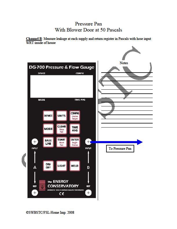
WAP PRESSURE DIAGNOSTIC PROCEDURE
                                                                Contents

1. Introduction........................................................................................................ . 4

2. Baseline ............................................................................................................... 5

3. Dominant Duct Leakage ...................................................................................... 7

4. Room Pressures ................................................................................................. 10

5. CAZ...................................................................................................................... 13

6. Combustion Safety ............................................................................................. 16

7. Static Pressure Test ............................................................................................ 19

8. Initial Blower Door Test (pressurize de-pressurize ............................................ 22

9. Air Sealing Budget procedure............................................................................. 27

10. Pressure Pan ....................................................................................................... 29

11. Estimating Total Duct Leakage ........................................................................... 31

12. Zonal Testing (Pressure Mapping ....................................................................... 32

                                                                                                                       Page 3
WAP PRESSURE DIAGNOSTIC PROCEDURE
                                                     Introduction

                                 Introduction

There are two main data collection procedures when conducting pressure diagnostics

on a home. First there are the tests that measure only the pressures created in the

home with the equipment in the home. In other words, the actual blower door does

not necessarily need to be set up. You will only need a few hoses and your

manometer. For the purposes of this guide, it will be assumed that the blower door is

set up in the front door of the home, but the fan cover is on. The second procedure is

when you have the blower door fan running, create a 50 Pascal pressure difference

and measure against that known pressure. At no point should your blower door fan

and ANY other exhaust fan or air handler fan be running at the same time.

This guide should be used in conjunction with the DG-700 Digital Manometer color

handout produced by the SouthWest Building Science Training Center.

Back To Table of Contents                                                         Page 4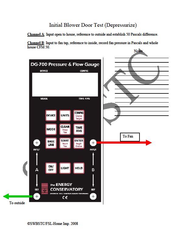
WAP PRESSURE DIAGNOSTIC PROCEDURE
Baseline
STEP 1 - SETTING BASELINE & SETTING HOUSE INTO BASELINE MODE
Baseline Mode is having all exterior doors and windows closed, and all interior doors
open. All exhaust fans and air handlers turned off. Your goal is to separate the indoors
from the outdoors. During an initial assessment, you are simply collecting data. You
should not fix anything to set up for pressure testing. If there is a manual or
mechanical damper connected to an evaporative cooler, or to the duct work that
separates an evaporative cooler from an air conditioning (AC) system you should close
it. If no damper is present, then that is how that house has been operating and your
data should reflect that. In the case of a doggy door, you should fasten it closed with
some painters tape. It is important to maintain your “Adjusted Baseline” throughout
all of the testing until you have completed the “CAZ” test. If you accidentally lose the
“ADJ” under the “A” channel window, you must re-baseline your gauge before
conducting a CAZ test.
Once the home is set up, follow the directions on fig. 1. Setting Baseline
You should have a hose to the outside on your channel A ‘Ref’ port.
All other pressure ports should be open.
You will be monitoring numbers in the A channel window.
Press “Baseline”
Press “Start”
Back To Table of Contents Page 5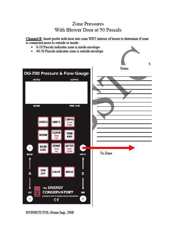
WAP PRESSURE DIAGNOSTIC PROCEDURE
Baseline
Wait for the number in the A channel window to settle and lock on a number
(30 seconds)
Press “Enter”
To Outside
FIG. 1
NOTE: Baseline is not intended to compensate for wind in any way. It is simply
looking at the natural pressure between the inside of the home With Reference To
the outside. You should not attempt to do a Baseline on a windy day.
Back To Table of Contents Page 6WAP PRESSURE DIAGNOSTIC PROCEDURE
Dominant Duct Leakage
STEP 2 - DOMINANT DUCT LEAKAGE
Your next test will be to determine the “Dominant Duct Leakage”. Refer to Fig 2
To Outside
FIG. 2
You should notice that nothing is changing with how the manometer is set up, and
nothing is changing with how the house is set up. You will be pressing no buttons on
your manometer.
Turn on air handler. If you have multiple Air Handlers, turn on “1” record
number, then turn on “2” and record combination number, then shut down “1”
to record the impact only the “2” air handler creates on the home etc.
Back To Table of Contents Page 7WAP PRESSURE DIAGNOSTIC PROCEDURE
Dominant Duct Leakage
Make sure air handler is running at full speed.
NOTE: Some high efficiency heating and cooling equipment may have multi-speed
fans. These need to be running at full capacity. This can usually be accomplished by
setting the Thermostat to the lowest possible temperature setting for AC and waiting
for 8 minutes, or the highest temperature possible for heating systems.
You are still monitoring the “A” Channel numbers. As the air handler winds up to full
speed, you will usually see a pressure appear on your manometer. While you do need
to keep the number in mind for other tests coming up, for the purposes of the
“Dominant Duct Leakage” test, the positive or negative is the more important piece of
information.
A positive pressure implies that you have more leakage on the RETURN side of the
duct system than the supply side.
A negative pressure implies that you have more leakage on the SUPPLY side of the
duct system than the return.
NOTE: This test does not show either side as being leak free. Just that one side may
be leaking MORE than the other. If you see no pressure changes at all, there could be
several things to consider.
1. You may have left a window or door open to the outside. Double check this
first. And if so, close it and start over from “Setting Baseline”
Back To Table of Contents Page 8WAP PRESSURE DIAGNOSTIC PROCEDURE
Dominant Duct Leakage
2. You may have left the cover off of your blower door fan. If this is the case,
cover the fan and start over with “Setting Baseline”
3. Your duct system may be leaking EQUALLY on both the return and supply
sides, and that will be determined later in this procedure.
4. Your house may have excessive shell leakage and that will be determined
later in this procedure.
Record your “Dominant Duct Leakage” number and specify if it was a negative or
positive number. Record this data for each AHU (Air Handler Unit) working alone and
in combination with other AHU’s operating.
Example: Dominant Duct:
1=-0.3
1+2= -1.3
2=-1.0
Note that both Air handlers must be
running for the next test “Room
Pressure’s” and these numbers will have
an impact on your CAZ procedure.
Back To Table of Contents Page 9WAP PRESSURE DIAGNOSTIC PROCEDURE
Room Pressures
STEP 3 - ROOM PRESSURE TESTING
This test is designed to see what happens to the pressure balances in the home when
interior doors are closed. Refer to Fig 3.
To Room
FIG. 3
You will be testing various ROOMs with reference to INSIDE.
For a room to qualify for a room pressure test, it must have a supply register, and / or
a return register and / or an exhaust or supply fan and a door. This includes bathrooms
and laundry rooms.
Back To Table of Contents Page 10WAP PRESSURE DIAGNOSTIC PROCEDURE
Room Pressures
The procedure for this test is to perform all room pressure testing clockwise from the
blower door. If your door is set up in the front doorway, you would look at it and walk
to your right hand side and test the first qualified room you come too.
Place ‘INPUT’ pressure hose a few feet into room.
Close door. Record pressure number and if it is positive or negative.
The Arizona WAP dictates that no room should exceed +/- 3 Pascal’s of pressure. If
your room DOES exceed 3Pa, the next step is to determine what it will take to alleviate
the pressure. You can do this by cracking the door open slowly until the pressure drops
to within limits, then calculating the net free square inches you opened the door by
multiplying the height of the door in inches by how many inches you cracked it open.
EXAMPLE: If my manometer reads 9.6 Pascal’s and I cracked the door two and a half
inches to get the pressure down under 3Pa. I would measure the Height of my door, in
this example, 80 inches and multiply that number by 2.5. That would let me know that
this particular room needs approximately 200 Square Inches of “Passive Return”
Conversely, if you are testing rooms with a supply register but no return system, and
do not see a pressure exceeding 3Pascal’s, that should be considered a flag for further
investigation. For example: A low room pressure could indicate a crushed or
disconnected duct, or maybe excessive shell leakage in that room. Once done with the
actual room pressure, you may collect one more piece of information while at each
Back To Table of Contents Page 11WAP PRESSURE DIAGNOSTIC PROCEDURE
Room Pressures
room that is used for the next test. Once you have collected the room pressure and
the amount of area needed to relieve that pressure, look around that room for any
type of exhaust fan.
NOTE: A clothes dryer is an exhaust fan.
If you see an exhaust fan, turn it on, close the door and note the new pressure. If the
room goes into a negative pressure, this is VERY IMPORTANT information for the CAZ
test and should be noted. A good example of note keeping for this particular test
would look like this.
9.5 / 200 / -1.2
This first number is the initial
positive pressure recorded.
This second number is the height of the door X the amount
you opened the door in inches.
The third number shows that there was an exhaust fan that created a negative
pressure.
Back To Table of Contents Page 12WAP PRESSURE DIAGNOSTIC PROCEDURE
CAZ
STEP 4 - “CAZ TEST”
NOTE: The CAZ test, as far as health and safety goes, is the single most important
test an energy assessor performs. You MUST have a baseline on your manometer
prior to performing this test. If you have no formal training in this area, STOP. You
are not qualified to perform this test alone.
Refer to Fig. 4 – “CAZ Test” for manometer set up.
To CAZ
Outside
FIG. 4
Back To Table of Contents Page 13WAP PRESSURE DIAGNOSTIC PROCEDURE
CAZ
The first step in a proper CAZ test is to set the actual CAZ into “Worst Case Scenario”.
In MOST cases this is easily accomplished with 3 simple steps involving information
you have already collected to this point. If your Dominant duct leakage from step one
is a NEGATIVE number follow these next three steps:
1. Turn on all exhaust fans. This includes the range hood, bath fans and the dryer.
Your air handler should still be running if you have followed every step to this
point.
2. Close all interior doors that have a positive pressure, and open all interior doors
that have a negative pressure behind them, any doors that appear to have no
pressure behind them at all should be closed. (It is very possible to have a
bathroom with an operating exhaust fan where the door will still be closed
because there is more supply air than is being exhausted by the fan. This was
determined by your Room Pressure Tests)
3. Run ‘Input’ hose to each individual CAZ WRT outside and record the number.
NOTE: If there is a door between the main body of the home and the CAZ, e.g.: Water
heater in a closet. Test your CAZ with that door open, then check again with the door
closed and record the GREATER negative number. For example, a reading of -3.9 is
GREATER than -3.1 and therefore your CAZ TEST Number for that particular CAZ is -3.9.
IF your Dominant Duct Leakage Number from step 2 was a POSITIVE number, you
should follow steps 1 through 3 above, but test each CAZ with air handler ON then
Back To Table of Contents Page 14WAP PRESSURE DIAGNOSTIC PROCEDURE
CAZ
again with air handler OFF to see which has the greater negative depressurization.
NOTE you may have scenarios where multiple AHU’s will have an impact on what
creates “worst case scenario”.
No home in the WAP program should have a CAZ zone with a pressure less than -
3.0Pa
The CAZ test should only be performed under the supervision of a trained
professional.
Back To Table of Contents Page 15WAP PRESSURE DIAGNOSTIC PROCEDURE
Combustion Safety
STEP 5 - COMBUSTION SAFETY
Once your home is in “worst case scenario” that is when you will perform all
“Combustion Safety Tests. These tests should only be performed by someone that
has been professionally trained or Certified.
It is recommended that you use and follow the combustion safety process highlighted
in the “Combustion Safety App” included in this field guide package.
SWS # 2.0201.1
Emergency problems (e.g., gas leak, ambient CO levels that exceed 35 ppm) will be
communicated clearly and immediately to the customer and appropriate solutions will
be suggested
FUEL LEAK DETECTION:
An electronic gas leak detector should be base lined outside in a clean air
sample area before being brought into a CAZ area.
Test all gas, oil or propane fuel lines at all connections and the entire lengths of
any flexible piping for leaks. Any positive leak indications from an electronic
detector should be verified with soap and water solution.
Scope of work will specify any repairs needed to correct fuel leaks of any kind.
Back To Table of Contents Page 16WAP PRESSURE DIAGNOSTIC PROCEDURE
Combustion Safety
COMBUSTION AIR REQUIREMENTS:
Combustion air will meet IRC 2012 Section G2407.5 guidelines
Volume of air indoors to supply a device will be no less than 50 Cubic Feet per
1000BTU’s of input for all devices in the space. Air volume must be always
accessible, and measured shell leakage of the building cannot be below 0.4
ACH.
If outside air is to be brought into the CAZ, at a minimum you will supply two
separate inlets. One that terminates within 12 inches from the ceiling, and
another that terminates within 12 inches of the floor. If inlets are horizontal
(through a wall) 1 Square inch, Net Free area will be provided for every 2000
BTU/hr input of all equipment in the CAZ, OR combustion air can be brought in
vertically (From vented attic space) providing a minimum of 1 Square inch, net
free area per 4000 BTU/hr of combined input for all atmospheric vented
appliances.
FLUE PIPE / EQUIPMENT INSPECTION:
All flue pipes will be visually inspected to verify they are the right size.
Slope a minimum of ¼” rise per foot of run.
Are free from blockage or excessive damage, leaks, disconnects, or other safety
hazards.
Back To Table of Contents Page 17`WAP PRESSURE DIAGNOSTIC PROCEDURE
Combustion Safety
SPILLAGE TESTING:
In worst case depressurization mode, all non-mechanically assisted drafting
devices must be tested for spillage at the diverter. If a device continues to spill
flue gasses after 2 minutes, it must be tested again at natural conditions to
determine if the failure is pressure induced or an issue with the device itself.
Any failure of spillage testing requires specifications on how to mitigate the
issue under any operating conditions.
UNDILUTED CARBON MONOXIDE TESTING:
Carbon Monoxide production levels must be measured in all combustion
appliances. In atmospheric, natural drafts appliances, this will be performed at
the exhaust ports before the gases can mix with dilution air. In Mechanically
Assisted or Sealed Combustion appliances this test is performed at the outdoor
termination of the flue pipe.
No appliance can exceed 200ppm undiluted, or 400ppm ‘Air Free’ at steady
state efficiency.
If CO levels exceed these limits in worst case conditions, they should be re-
tested at natural conditions to determine if the failure is due to CAZ pressures
or the device itself and appropriate actions to mitigate the problem should be
added to the scope of work.
Back To Table of Contents Page 18WAP PRESSURE DIAGNOSTIC PROCEDURE
Static Pressure Test
STEP 6 - EXTERNAL STATIC PRESSURE TEST
Refer to Fig. 6 for manometer set up.
To Return To supply
FIG. 6
The static test is meant to measure the static pressures created in the Air Handler itself
when operating normally. There actually needs to be two tests performed. One with
the air filter in place, and one with it removed and equipment operating without an air
filter. In both cases, all interior doors of the home should be opened back up, and all
the fans that were turned on for “Worst Case Scenario” should now be turned back
off. Any supply registers that have been closed or covered should be opened up.
Back To Table of Contents Page 19WAP PRESSURE DIAGNOSTIC PROCEDURE
Static Pressure Test
These tests are performed by drilling two 5/16” holes into both the supply and return
plenums as close as you can get to the air handler without drilling into an Air
Conditioning coil. Insert a draft probe into each hole insuring that both probes are
pointing into the air-stream. In other words, your probe in the supply plenum would
be pointing TOWARDS the air handler, while the probe in the return plenum would be
pointed AWAY from the air handler. To switch the units of measurement on a DG-700
simply press the “Units” button once. You will record a number that looks similar to
this: .5000 Repeat this test with the air filter removed and record that number as
well. Most heating and cooling air handler equipment has a manufacturer’s tag with
the model number and serial number on it. Usually on that same tag you will also find
the “Max External Static Pres. xxxx iwc”
Because you are testing pressures separately on both channels of your manometer you
can simply add the two numbers together ignoring the “-“ (Negative) sign. For example
Supply = 0.350 iwc
Return = -0.410 iwc
Total TESP = 0.760
Back To Table of Contents Page 20WAP PRESSURE DIAGNOSTIC PROCEDURE
Static Pressure Test
Compare your number to the number on the tag. This will tell you if the duct system is
operating at excessively high static pressures due to an undersized return system
among other things. You will notice that the number increases with an air filter and
even more with dirty filters. Both the supply and the return sides should be about Half
of the max pressure recommended by the manufacturer.
Alternatively, you can look up the “Blower Performance Chart” provided by the
manufacturer of the air handler unit. This chart estimates the volume of air the unit is
moving based on the Total External Static Pressure. ACCA standards recommend an air
flow in air conditioning units to be between 350-450 CFM per ton of air conditioning
capacity. It is recommended in hot dry climates that you get to the higher end of that
range for optimum efficiency.
Back To Table of Contents Page 21WAP PRESSURE DIAGNOSTIC PROCEDURE
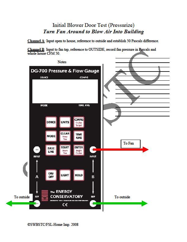
Initial Blower Door
STEP 7 - INITIAL BLOWER DOOR
First step in preparing for an initial blower door test is to set the house back into
BASELINE mode Note that you should still have a baseline on your gauge before
conducting this test. All exterior doors and windows should still be closed, and all
interior doors should now be open, and exhaust fans OFF, from the static pressure
testing. Your air handler can now be turned off. You should set all atmospheric
combustion appliances in the home to OFF or PILOT and place your car keys on the
water tank so that you cannot drive away without returning all equipment to
operation positions.
As and energy assessor, you must now make a decision as to whether you want to
“pressurize” or “de-pressurize” for your testing. Here are some considerations.
If any of the following conditions exist, you CANNOT depressurize:
You find mold anywhere in the home
You find Vermiculite insulation in the attic
You suspect any friable asbestos is present in the home
There is a fire burning in a fireplace within the home
You suspect there may be lead dust from lead based paint in the home
You may NOT want to depressurize if there are any ashes in a fireplace within the
home, however wet newspaper carefully laid out will usually hold the ashes down on a
Back To Table of Contents Page 22WAP PRESSURE DIAGNOSTIC PROCEDURE
Initial Blower Door
depressurization test. When looked at carefully, there are really only two benefits to
De-pressurization testing.
1. The blower door is designed to give you access to the rings in the fan only
when set up in De-pressurization mode.
2. You can feel infiltration on your skin when the door is operating at 50pa.
When you consider the dollar value of infiltration repair in some climate Zones in
Arizona, being able feel infiltration is not really much of a benefit, but the potential to
pull Mold spores, Lead dust, or Asbestos into the family’s living space is quite a
downside. If you do choose to Pressurize with the blower door, check for ‘Up-Ducts’,
and temporarily hold all exhaust fan dampers closed with tape. Make sure that the
manual gates that can be closed are in fact closed, and the spring or barometric
controlled dampers are temporarily held closed.
NOTE: In order to ‘Pressurize’ for blower door testing, you MUST turn the entire fan
around. You CANNOT flip the flow reversing switch that is on some fans, this will give
very in-accurate numbers.
Back To Table of Contents Page 23WAP PRESSURE DIAGNOSTIC PROCEDURE
Initial Blower Door
To “Pressurize” see fig 7
To “De-Pressurize” see fig 8 for manometer set up.
FIG 7
Back To Table of Contents Page 24WAP PRESSURE DIAGNOSTIC PROCEDURE
Initial Blower Door
FIG 8
Back To Table of Contents Page 25WAP PRESSURE DIAGNOSTIC PROCEDURE
Initial Blower Door
Once you are all set up, choose which ring you feel will be appropriate for the home
you are testing. There are a couple rules of thumb that many people like to use. The
reality is that it is in fact just a guess at this point. My experience has been that starting
with the ‘A’ ring is a good guess. To start you should turn your rheostat clockwise
increasing the fan speed until you achieve 50Pa on your ‘A’ channel. This is the HOUSE
With Reference To Outside. From this point forward, all testing will be performed with
the house at this 50Pa pressure differential with reference to the outside.
At this point a couple of things must happen. First you should verify that you have a
minimum of 25Pa on your ‘B’ channel. If you do, you can skip ahead to the next step. If
however you’re ‘B’ channel is less than 25Pa, you will have to add another flow ring to
your fan to increase the pressure inside the fan housing in order to produce an
accurate CFM Flow number. Once you have 50Pa on your ‘A’ channel and a minimum
of 25Pa on your ‘B’ Channel you will need to push the “MODE” button. This will switch
the ‘B’ channel window from ‘Pa’ to ‘CFM’. You should also notice that at the top left
hand side of that same window you will see “OPEN”. This is referring to your fan
configuration. If you have an open fan, then the number you see above ‘CFM’ in the ‘B’
channel window is your CFM50 number. If you had to use a flow ring to get to this
point you will have to tell the gauge which ring is in the fan. Press the “CONFIG” button
and you will see the word “OPEN” scroll through the options available to the DG-700.
You would press the button once for “A” ring, twice for “B” ring and so on. If you
accidentally skip past your ring, just keep pressing “CONFIG” and you will see it
Back To Table of Contents Page 26WAP PRESSURE DIAGNOSTIC PROCEDURE
Initial Blower Door
scroll back to its original setting. The number you need here is pretty simple. It is a
“CFM@50Pa” number.
If you are unable to achieve 50 Pascal’s due to a very leaky home, you can push the
“Mode” button again for a calculated flow at an estimated 50 Pascal’s.
This is the whole house leakage number and is very important in weatherization for a
few reasons. If you look carefully at the two windows in your manometer, you will see
how this number is formed.
AIR SEALING BUDGET PROCEDURE
Let’s say for example that the test reads:
2000CFM50
The “2000” is the number in the ‘B’ channel, and directly below that you will notice
“CFM”. In the ‘A’ channel, you should always see “50” and below that number “Pa”. So
when you break it down, you have 2000 Cubic Feet per Minute moving through the fan
at 50 Pascal’s of pressure.
The Weatherization Assistance Program has established within its priority lists, dollar
amounts that can be spent when dealing with infiltration you find with your ‘CFM50’
number. The following procedure explains what to do with your ‘CFM50’ number to
determine how much money can be spent to seal these holes. Let’s use the previously
Back To Table of Contents Page 27WAP PRESSURE DIAGNOSTIC PROCEDURE
Initial Blower Door
mentioned number of 2000CFM50 as an example. You can calculate how much to seal,
and how much you can spend to accomplish that goal.
2000CFM50…Blower door reading
1100CFM50…Where I want to be.
900CFM50…Infiltration sealing
900 ……………Square inches to
seal
900 X $35.oo .Budget
I have $315.oo max. To seal 900CFM50
Can you seal 90 square inches of holes in the shell of this building for less than $315
dollars? That includes the time and materials to find and seal these penetrations. An
effective tip is if you see a hole that you think is actually shell leakage, tape it off with
Duct Mask and re test your home. If the infiltration drops 100CFM50 for example, ask
yourself: Can I seal that hole for $35?
Remember: this dollar amount varies greatly depending on climate zone AND building
type. Consult your priority list for building type and climate zone to determine your
specific dollar amounts.
Back To Table of Contents Page 28WAP PRESSURE DIAGNOSTIC PROCEDURE
Pressure Pan Testing
STEP 8 - PRESSURE PANS TESTING
SEE FIG 9
FIG 9
Back To Table of Contents Page 29WAP PRESSURE DIAGNOSTIC PROCEDURE
Pressure Pan Testing
In this test you are looking for the answers to two main questions.
1. Is the duct system leaking?
2. Where is the location of the majority of the leaks?
This test will NOT tell you how much leakage there is, only that there is leakage, and
the approximate location of that leakage.
You will notice that at this point we have removed our green reference hose from the
‘A’ channel reference port. You are now able to disconnect yourself from the blower
door by removing the pressure hoses from the manometer. DO NOT ADJUST THE
RHEOSTAT. If left alone, the blower door will maintain the 50Pa pressure difference
between the indoors and outdoors. Though you will no longer see it on your
manometer, that pressure is there.
NOTE: This test only works if the home is at 50Pa of pressure. If you could not
achieve that pressure you will have to use an alternative method to estimate duct
leakage or temporarily seal shell leakage, or run a second blower door so that you
can achieve 50Pa of pressure.
You must now hook up your pressure pan to the ‘B’ channel input tap with a pressure
hose. Starting from the blower door, you will want to go clockwise around the house,
Back To Table of Contents Page 30WAP PRESSURE DIAGNOSTIC PROCEDURE
Pressure Pan Testing
ground floor first then second floor clockwise from the top of the stairs and record ALL
the pressures you find in EVERY supply and return register. Any reading of 1.0Pa and
over is an indication of a leaky duct system. The larger the number the closer to the
leak you are in most cases. The goal of the WAP program is to see the duct system
become as leak free as possible. Less than 1pa at all supply and return registers
indicates a “relatively leak free system”.
Note: If two registers are within 6’ of each other in the same run, you should tape
one register off completely and just record the pressure in the other register. If your
pressure pan does not completely cover any register, it is acceptable to tape that
register off enough to where your pressure pan will then completely cover it.
ESTIMATING TOTAL DUCT LEAKAGE
Estimating Total Duct Leakage to the Outside:
Because your priority lists, or a computer modeling software will require a total duct
leakage measured @25Pa or @50Pa you can use the “Pressure Pan / Duct Sealing
potential calculator” included in this field guide to calculate a total leakage number
based on average pressure pan readings collected in this test.
Back To Table of Contents Page 31WAP PRESSURE DIAGNOSTIC PROCEDURE
Zonal Testing
STEP 9 - ZONAL PRESSURES (aka. Pressure mapping)
See FIG 10
FIG 10
Back To Table of Contents Page 32WAP PRESSURE DIAGNOSTIC PROCEDURE
Zonal Testing
NOTE: House must be at 50Pa for this test to work properly.
The Zonal tests or “Pressure Mapping” are the tests that show the energy assessor
where the actual air barriers of the home are located. Up to this point, we generally
assume that the sheetrock on the inside of the exterior walls, the ceiling and the floor
make up the surfaces that separate the inside conditioned air from the outside. Zonal
tests will demonstrate where the air barriers are located in reality. You cannot visually
see air barriers, but your manometer can.
Note: Although the WAP only requires you to report the zone that contains the duct
system, that in no way implies that only one zonal test needs to be taken. A good
energy assessor will take upwards of twenty quick tests or more and determine
exactly where the actual air barriers are for better or worse.
When determining air barriers, there is a scale that tells you what is inside the
pressure boundary and what is outside that boundary, and what is neither in nor out,
but ‘confused’.
Inside “Confused” Outside
0-10Pa 11-39 Pa 40-50Pa
Back To Table of Contents Page 33
PWAP PRESSURE DIAGNOSTIC PROCEDURE
Zonal Testing
With a pressure hose connected to your manometers ‘B’ Channel ‘Input’ Tap, and the
other end attached to your pressure probe or pressure pan, and with the blower door
still running the house at a 50 Pascal pressure difference with the outside. You can
begin testing any area’s you suspect may have faulty pressure boundaries as well as
verifying areas where the pressure boundary should in fact be. Good areas to always
test are:
1. Drop soffits
2. Chases
3. Interior walls
4. Archways
5. Wet walls
6. Ceilings
7. Floors (if home is not slab on grade)
8. Interior walls alongside staircases
9. Build-outs around showers and baths
In general, what you are looking for is that anything that should be inside your home
eg. Interior walls and soffits are in fact inside the pressure boundary. Meaning you see
readings of 10 or less Pascal’s on your manometer. Whereas areas that should be
outside the home e.g. Attics, attached garages and crawlspaces, are reading above 40
Back To Table of Contents Page 34WAP PRESSURE DIAGNOSTIC PROCEDURE
Zonal Testing
Pascal’s on your gauge. If you have attended quality professional building science
training, you will know that in direct contact with your pressure boundary should
always be a continuous thermal boundary. That is easy to spot. It’s the insulation. At
ANY time, if you know there is insulation covering a plane, and a zonal test shows that
plane is less than 40 Pascal’s, that insulation is NOT performing properly. Conversely
you may test a ceiling plane and get a reading of above 40 showing that the ceiling
plane is an effective air barrier, but later on in your audit you see that the insulation is
up at the roof deck, you are in fact looking at an un-insulated attic. The thermal
boundary must be 100% continuous around the envelope of the building (exterior
walls, floor and ceiling / roof deck) and the pressure boundary must be 100%
continuous around the envelope, and most importantly, the pressure boundary and
the thermal boundary must be in 100% contact with each other to perform properly.
While your eyes can locate the thermal boundaries, only your manometer and blower
door can locate the pressure boundaries. So take lots of tests. Find the pressure
boundaries everywhere in that home and determine if it is in contact with the thermal
boundary. That is why this test is also known as ‘Pressure Mapping’.
Back To Table of Contents Page 35You can also read