Distributed I/O and RTU replacement solution SMP IO-2330-C1 combo system - SMP IO-2330-C1 Catalog Data
←
→
Page content transcription
If your browser does not render page correctly, please read the page content below
[Product#]
 SMP IO-2330-C1
 Catalog Data      New issue August 2021
                   Supersedes January 2021
 CA912014EN

 Distributed I/O and RTU replacement solution
 SMP™ IO-2330-C1 combo system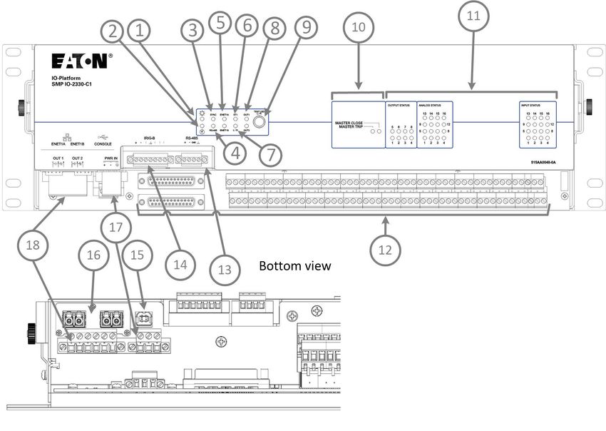
Contents
Contes

Catalog Data                                                                                                                                                        1
         The SMP IO-2330 system....................................................................................................................... 1

         General features...................................................................................................................................... 2

         Cybersecurity...........................................................................................................................................3

         Benefits....................................................................................................................................................3

         System architecture and I/O features......................................................................................................4
             Front panel.......................................................................................................................................7
         Specifications (physical characteristics)................................................................................................ 10

         Certifications and compliancy notes...................................................................................................... 18

         Type test details.................................................................................................................................... 19
         Temperature derating............................................................................................................................ 22

         Dimension drawings.............................................................................................................................. 23

         Ordering information.............................................................................................................................. 23

         Accessories and cables.........................................................................................................................30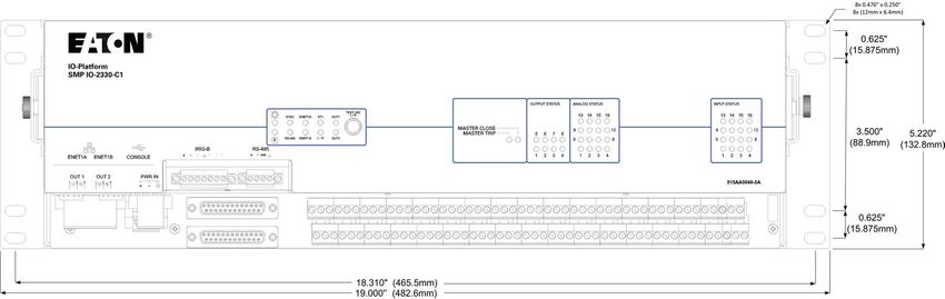
SMP IO-2330-C1 combo system                                                                              Catalog Data CA912014EN
                                                                                                                     Issue Date August 2021

 Catalog Data

 The SMP IO-2330 system
                Description                                                  SMP Gateway automation platform

                The SMP IO-2330-C1 is a distributed I/O unit which is        Both Eaton’s SMP SG-42xx automation platform models
                part of Eaton's SMP IO-2000 series and is used with          are substation-grade gateways with a proven history in
                the SMP Gateway automation platform for Eaton's RTU          data acquisition and distribution automation applications,
                upgrade solution, to replace legacy RTU systems.             as protocol conversion device and integration solution
                The hardware layout of the SMP IO-2330-C1 is based           for secure IED remote access. They are recognized
                on the legacy GE D20 I/O peripheral of the same type,        as one of the most efficient and reliable automation
                matching exactly the I/O mapping of the legacy product.      platforms on the market and are perfect for distributed
                However, the functionality is based on the SMP IO-2000       automation.
                series, our latest generation of distributed I/O platform.
                                                                             SMP IO-2330 system
                RTU upgrade solution
                                                                             SMP IO-2330's software functionality is based on
                Eaton’s RTU upgrade solution provides utilities with a       Eaton’s SMP IO-2000 series which is specially designed
                cost-effective answers to upgrading legacy RTUs with         to meet modern industry and utility requirements. It
                cybersecurity as a priority. Based on the utility hardened   is fully integrated with the SMP Manager and Tools
                and proven Eaton’s SMP family of substation automation       application for device configuration and maintenance.
                products, the SMP SG-42xx automation platform and on         It integrates seamlessly with the SMP Gateway
                the SMP IO-2330 distributed I/O unit, our RTU upgrade        automation platforms–simplifying both system setup
                solution supports most legacy RTU configurations.            and commissioning. The hardware layout is however
                Eaton's RTU upgrade solution is easily adaptable to any      different from the SMP IO-2230 unit to accommodate
                specific RTU deployment scenarios (e.g. GE D20), is          customers' needs with a 3U form factor, smaller depth
                wall- and rack- mountable and all connections are at the     and all connectors located at the front of the device
                front of the units.                                          which makes it perfect for a wall-mount installation in a
                The solution keeps the legacy RTU existing field wiring,     confined space.
                allowing for great cost savings on field installation man-
                hours and service interruptions.                             The SMP IO-2330 system uses a template-driven
                                                                             configuration tool, SMP Config, and includes numerous
                                                                             cybersecurity features to help utilities meet their
                                                                             compliance requirements, including NERC CIP (certified
                                                                             under UL 2900-1 for firmware version 2.0).

                                                                             Open frame options
        Figure 1: Eaton's complete upgrade solution
                                                                             The SMP IO-2330 system can be acquired in different
                                                                             sections based on your needs. The open frame
                                                                             options include the logic panel for data acquisition
                                                                             and communications (EDAC, SMP IO-2830) and the
                                                                             terminations panel (ETRM, SMP IO-2730), for each
                                                                             offered model.
        Figure 2: Eaton's open frame option (Eaton's EDAC over
        existing GE D20 WESTERM)                                             An EDAC panel can be associated to an existing Eaton's
                                                                             ETRM panel or to a GE D20 WESTERM panel of the
                                                                             same model. An ETRM panel is only compatible with
                                                                             an Eaton's EDAC panel of the same model; it can be
                                                                             used to replace a defective WESTERM panel that is
                                                                             connected to an Eaton's EDAC logic panel.

www.eaton.com/smartgrid                                                                                                           page 1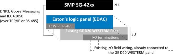
Catalog Data CA912014EN                                                                  SMP IO-2330-C1combo system
Issue Date August 2021

General features

  Hardware                                                   Software

   • Form factor: 3U wall- or rack-mount, all connections    •   Linux®-based operating system
     located at the front of the device                      •   Seamless integration with the SMP Gateway
   • Pre-mapped I/O offer with 4 models                      •   Access to SMP Manager's Tools
   • Individual LEDs for each I/O and application LEDs       •   Remote management (firmware upgrade, setting
   • No moving part                                              changes, license update)
   • Two built-in Form C relays for system alarm and         •   Configuration with SMP Config (also for standalone
     control (configurable)                                      units), multi- protocols/instances, configurable point
   • System status LEDs                                          mapping
   • Application LEDs (model-dependent)                      •   Offline and template-driven configuration
   • Multi-function button (Local/Remote selector and Test   •   Use of SMP Stats, SMP Log and SMP Trace
     LED)                                                    •   Micro PLC for local programmable logic (fast and
   • USB 2.0 maintenance port (Type B)                           complete PLC functions)
   • Protected against polarity reversal for power supply    •   Ready for remote management via Enterprise
   • Supported polarity reversal for Inputs/Outputs              Management Software (IMS)
                                                             •   System alarms
  Protocols
                                                             Mapping
   • DNP3, IEC 61850, GOOSE (Serial or TCP/IP links)
   • DNP3 event queue (up to 1000 events/slave)              • Predefined mappings
   • Up to 5 server instances                                • Serial number, version, internal status, current time,
                                                               last reset time and more are available in the protocol
                                                               mapping
  Communication and Web interface                            • Exportable DNP3 protocol device XML profile

   • RS-485 serial interface
   • 2 x 10/100 Mb/s Ethernet ports or 2 x 100 Mb/s          System
     optical Ethernet ports
   • Daisy chain Ethernet capabilities                       • Integrated self-diagnostics
   • Web interface for I/O commissioning                     • Integrated watchdog timer
   • Secured remote maintenance using transparent            • Real-time clock (with battery backup)
     connection (SMP Gateway and IMS passthrough)            • Internal clock synchronization using IRIG-B, NTP or
                                                               via protocols
                                                             • Local/Remote switching mechanism and state (logical
                                                               points)
                                                             • Logs support (Security, System)

page 2                                                                                         www.eaton.com/smartgrid
SMP IO-2330-C1 combo system Catalog Data CA912014EN
Issue Date August 2021
Cybersecurity
• UL2900-1 compliant for firmware version 2.0: • Access management (log, lockup, etc.)
Standard for Software Cybersecurity for Network- • Account management:
Connectable Devices - Strong passwords
• IEEE 1686-2013 compliant - Single Admin account
• Integrated Ethernet firewall - User accounts and user groups
• Ability to disable any unused port (report enabled- - Detailed group permissions
disabled ports) • All system components digitally signed
• Secure maintenance connection (TLS) via • Settings integrity validation
SMP Gateway Passthrough or via direct SMP • Factory reset in case of Admin password loss
Manager connection
• AES-128/256 encryption
• Secure USB maintenance port
• Secure command shell
Benefits
With its robust and scalable design, Eaton's RTU upgrade solutions are flexible and adapts to evolving automation
requirements.
Reliability Easy integration
• Designed to evolve through regular software and • Complete support for the SMP Tools
firmware updates, ensuring a future-proof automation • Easy configuration using SMP Manager's
system SMP Config
• Helps meet NERC CIP requirements by securing • Simplified pre-loading operation of existing
IED remote access and enhancing SCADA configuration into the SMP Gateway prior to
communication links installation
Scalability Productivity
• Use of open industry protocols (standard DNP3, • 70% labor cost reduction compared to a traditional
GOOSE messaging or IEC 61850 over a TCP/IP or RTU upgrade solution due to the use of existing
RS-485 link) with over 80 protocols to integrate other wiring
IEDs in the substation via the automation platform • Offline configuration tools
• Web interface for I/O commissioning
• Uses the same management applications as the
SMP Gateway automation platform (SMP Manager)
• Seamless I/O integration between the SMP Gateway
and distributed I/O unit
• Enhanced automation capabilities using the IEC
61131-3 SoftPLC of the SMP Gateway automation
platform and/or the micro PLC of the SMP IO-2330
distributed I/O unit
www.eaton.com/smartgrid page 3Catalog Data CA912014EN SMP IO-2330-C1combo system
Issue Date August 2021
System architecture and I/O features
The following I/O features are available for the RTU upgrade solutions, I/Os types availability depends on the specific
model.
Analog inputs Binary inputs
• High/Low warning support • DC inputs
• Deadband, scaling and units • Tolerance/Intolerance filtering
• User calibration at fixed ambient temperature • Chatter protection
• Fail safe circuit (active level in normal state)
Binary outputs • Binary points software polarity reversal
• Timetag at the beginning or end of the filtering
• Output protection against single component failure (setting)
• Trip/close pair, Raise/Lower, latch, pulse and pulse • Persisted counters (total transitions, up/down
pair support direction), with deadband, scaling and roll over
• Pulse train command support detection.
• Persisted operation counter/operation time • Freeze, clear, freeze and clear counters support
• Binary points software polarity reversal
• Control queuing allows up to 10 parallel requests,
sequentially processed when the same point is
targeted
Table 1: RTU upgrade solution, available models
Type Model Available I/Os
Wall-mount or
Rack-mount SMP IO-2330-A Complete system for 32 analog inputs: disconnect terminations
(3U)
Logic panel for communications and for 32 analog inputs. This panel can
Open frame
SMP IO-2830-A be connected to an Eaton ETRM panel or GE D20 WESTERM panel of
EDAC (3U)
the same type.
Termination panel for 32 analog inputs. This panel can be connected to an
Open frame
SMP IO-2730-A Eaton EDAC panel of the same type. Can be used to replace a defective
ETRM (3U)
GE D20 WESTERM panel.
Complete Combo system offering :
Wall-mount or • 16 status and alarm inputs: disconnect terminations
Rack-mount SMP IO-2330-C1 • 8 control outputs: disconnect terminations with 2 x DB25 connectors for
(3U) connection to existing GE D20 interposing relays
• 16 analog inputs: disconnect terminations
Logic panel for communications and for the combo unit:
• 16 status and alarm inputs
Open frame • 8 control outputs
SMP IO-2830-C1
EDAC (3U) • 16 analog inputs
This panel can be connected to an Eaton ETRM panel or GE D20
WESTERM panel of the same type.
page 4 www.eaton.com/smartgridSMP IO-2330-C1 combo system Catalog Data CA912014EN
Issue Date August 2021
Table 1: RTU upgrade solution, available models
Type Model Available I/Os
Termination panel for the combo unit:
• 16 status and alarm inputs: disconnect terminations
• 8 control outputs: disconnect terminations with 2 x DB25 connectors for
Open frame
SMP IO-2730-C1 connection to existing GE D20 interposing relays
ETRM (3U) • 16 analog inputs: disconnect terminations
This panel can be connected to an Eaton EDAC panel of the same type.
Can be used to replace a defective GE D20 WESTERM panel.
Wall-mount or
Complete system for 32 binary outputs: disconnect terminations (K) or
Rack-mount SMP IO-2330-K
DB25 connectors (KR)
(3U)
Open frame Logic panel for communications and for 32 binary outputs.
SMP IO-2830-K This panel can be connected to an Eaton ETRM panel or GE D20
EDAC (3U)
WESTERM panel of the same type.
Termination panel for 32 binary outputs: disconnect terminations (K) or
Open frame DB25 connectors (KR)
SMP IO-2730-K
ETRM (3U) This panel can be connected to an Eaton EDAC panel of the same type.
Can be used to replace a defective GE D20 WESTERM panel.
Wall-mount or
Rack-mount SMP IO-2330-S Complete system for 64 status and alarm inputs: disconnect terminations
(3U)
Open frame Logic panel for communications and for 64 status and alarm inputs.
SMP IO-2830-S This panel can be connected to an Eaton ETRM panel or GE D20
EDAC (3U)
WESTERM panel of the same type.
Open frame Termination panel for 64 status and alarm inputs: disconnect terminations
SMP IO-2730-S This panel can be connected to an Eaton EDAC panel of the same type.
ETRM (3U)
Can be used to replace a defective GE D20 WESTERM panel.
www.eaton.com/smartgrid page 5Catalog Data CA912014EN SMP IO-2330-C1combo system
Issue Date August 2021
The SMP IO-2330-C1 configuration is fixed at 16 binary inputs, 8 binary outputs + 2 built-in binary outputs and 16 analog
inputs, the following features apply to this SMP IO-2330 system:
• Can be configured to be connected to a GE D20 KI • Master Close/Trip logic
interposing relay or to an LPL
• Local/Remote switch via the test LED L/R button
• 16 analog inputs: ±10 V, ±1 mA, ±2 mA, ±20 mA
• Control output methods (hardware and software
Note: Other input ranges will be available upon adjustable):
request. - Pulse duration
• Available mode for analog inputs: Voltage and - Latched-output (discrete timed/latch relay
Current with or without Loop Supply functionality supported)
• Shipped pre-configured according to the selected • All binary input changes are reported in the order they
mode for analog inputs occurred with accurate timetag
• An event is generated for each change of state of the • Wetting for status and alarm inputs is protected by a
status and alarm input that gets through debouncing 2A fuse, on both side of the wetting
(tolerance/intolerance filter), the current state of the • Counts on rising and falling edges of status and alarm
input is available inputs as well as for the total number of detected
• Each status and alarm input is photo-coupled transitions on each input
• Possible control output configurations:
- 8 Trip/Close pairs
- 6 Trip/Close pairs and 1 Raise/Lower pair
- 4 Trip/Close pairs and 2 Raise/Lower pairs
- 2 Trip/Close pairs and 3 Raise/Lower pairs
- 4 Raise/Lower pairs
- 8 isolated Form C contact control outputs
page 6 www.eaton.com/smartgridSMP IO-2330-C1 combo system Catalog Data CA912014EN
Issue Date August 2021
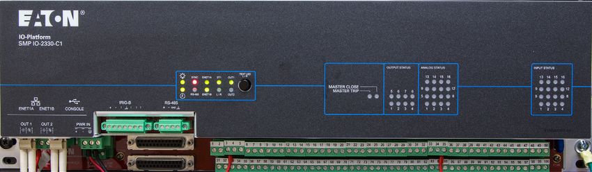
Front panel
This section describes the front panel of the SMP IO-2330-C1, all main components are identified.
Figure 3: The front panel of the SMP IO-2330-C1
The following table describes the front panel components related to the previous figure:
Table 2: Front panel components of the SMP IO-2330-C1
# ID Description
Power LED.
This LED indicates the status of the SMP IO-2330 system internal power supply.
1 Power LED
Note: Additional information about the power supply is also available from the SMP IO-2330
system, using the SMP Stats program.
Watchdog
2 Watchdog timer status LED.
LED
Clock synchronization LED.
3 SYNC LED This LED indicates the synchronization status of the SMP IO-2330 system connected to an
IRIG-B synchronization source.
4 RS-485 LED Built-in RS-485 serial port activity LED.
www.eaton.com/smartgrid page 7Catalog Data CA912014EN SMP IO-2330-C1combo system
Issue Date August 2021
Table 2: Front panel components of the SMP IO-2330-C1
# ID Description
LEDs Built-in ENET1A and ENET1B2 port activity LEDs.
5 ENET1A, The two Ethernet ports are used as Ethernet switches for daisy-chain connections. Each LED
ENET1B indicates the speed and activity level of the corresponding Ethernet port (switch).
Status LED 1.
6 ST1 LED This LED indicates the various steps the SMP IO-2330 system goes through during the startup
sequence.
Local / Remote control status LED.
7 L/R LED The local/remote interlock mechanism is a safety measure which totally disables the operation
of control outputs when set to Local.
OUT1 / OUT2
8 On board relay status LED, OUT1 and OUT2.
LEDs
Multi-function button used to:
• Test the SMP IO-2330 system front panel LEDs. When pressed, all LEDs should light.
Button • Switch the operation between Local and Remote operation. To do so, press and hold
the button during the first five (5) seconds during steady operation of the device (boot-
9 Test LED up sequence must be terminated), until the LEDs light up. The SMP IO-2330-C1 will then
or L/R switch between Local and Remote modes.
• Force the system to boot into rescue mode. To do so, press and hold the button during
the first five (5) seconds during the boot-up sequence, until the LEDs light up. The
SMP IO-2330-C1 will then boot in rescue mode.
LEDs specific to the SMP IO-2330-C1 model. They are:
Application • MASTER CLOSE
10 • MASTER TRIP
LEDs
The Master Close and Master Trip relays (Form A) are used for hardware control security
measure.
11 I/O Status I/Os activity/state for the 8 output status, 8 analog status and 16 input status.
LEDs Each LED indicates the input status of the point.
Terminal blocks (quick disconnect type) for connecting up to 16 Binary inputs, 8 Binary
Outputs and 16 Analog Inputs . The connectors are used to connect the existing field wiring to
the SMP IO-2330-C1.
When the binary outputs are configured in wetting mode (Trip/Close and Raise-Lower/Latch
output configurations only), a 2 A TL fuse is protecting the circuit.
Terminal Three (3) different configuration modes are available for each analog input, these are current,
12 blocks voltage and loop supply modes. The voltage or current mode is configurable by installing the
supplied configuration modules on the ETRM termination panel. To setup these modes:
• voltage mode (default)
• current mode
• current mode with voltage loop supply (module rotated 180 degree)
DB 25 connectors may be used to connect to GE D20 KI interposing relays (8 Trip/Close and
4 Raise-Lower/Latch pairs).
page 8 www.eaton.com/smartgridSMP IO-2330-C1 combo system Catalog Data CA912014EN
Issue Date August 2021
Table 2: Front panel components of the SMP IO-2330-C1
# ID Description
Terminal block reserved for the serial RS-485 communication (COM1)
• 2 wire RS-485 support (multidrop)
RS-485 serial • Up to 1200 m (4000 ft.)
13
port • Up to 32 devices (multidrop)
Baud rates supported on this port: 300, 600, 1200, 1800, 2400, 4800, 9600, 19200, 38400,
57600, 115200 bps
Terminal block reserved for the reception of a demodulated IRIG- B signal.
14 IRIG-B port Eaton recommends the use of a shielded cable with twisted 22 — 16 AWG wires for the IRIG-
B terminal block.
Type-B USB 2.0 port.
CONSOLE This port is used for maintenance and configuration of the SMP IO-2330 system; it is always
15
port enabled. This port is also used to access the SMP IO-2330 system's web interface to monitor
and control I/Os for commissioning.
Built-in Ethernet connectors (switch).
ENET1A, The following connector types are available for theses built-in ports:
16 • Shielded metallic RJ45 (standard)
ENET1B
• Fiber-optic LC (option)
Note: Both connectors of the built-in ports are of the same type.
Wiring terminals for the power supply.
PWR The power supply can accept an input range of 19.2 — 60 VDC.
17 Power supply Eaton recommends the use of a shielded cable with 18 to 12 AWG wires for the SMP IO-2330-
terminal block C1 power supply terminal block.
Note: If the SMP IO-2330-C1 is intended for use at ambient temperatures greater than
140°F (60°C), use a cable with a suitable temperature rating.
Two (2) NO/NC (normally open / normally closed) Form C relays:
OUT1 relay's NC contact is pre-configured for system health monitoring (application). Both
relays are available for system applications and can be activated through a system data output
point, if configured.
18 OUT1, OUT2
When configured for system health monitoring, the OUT1 relay's NC contact operates as
follows:
The relay's NC contact remains closed until the SMP IO-2330 system is started. Thereafter,
the contact is opened if the SMP IO-2330 system is working properly. In case of failure, the NC
contact closes.
www.eaton.com/smartgrid page 9Catalog Data CA912014EN SMP IO-2330-C1combo system
Issue Date August 2021
Specifications (physical characteristics)
Table 3: General specifications
General specifications
Height: 5.23 in. (132.8 mm)
Width: 19 in. (482 mm)
Dimensions No connectors on the rear panel
Depth: 2.8 in. (71 mm)
10 lb max (4.5 kg)
Back to back on panel (rack-mount) or
Installation
wall-mount
Warranty 10-year limited
Operating * : cTUVus safety marking is based on the
-40°F to +185°F * (-40°C to 85°C)
temperature temperature table.
Storage temperature -40°F to +185°F (-40°C to 85°C)
Humidity 5 to 95%, non-condensing
Degrees of protection IP00 IEC60529: 2013
provided by enclosure (design to meet IP30)
The MTBF value is obtained from the ratio of the
number of devices in operation over the actual
MTBF Real MTBF (practical): > 100 years
number of failures observed on devices of the
same SMP family.
Maximum altitude Up to 6561.7 feet (2000 meters)
Power
Watchdog
Clock synchronization (SYNC)
Build-in serial port (RS-485)
Build-in Ethernet ports (ENET1A,
ENET1B)
Status (ST1)
Status LED display
Local/Remote status LED for Control
outputs (L/R)
Relay status (OUT1, OUT2)
Master Close
Master Trip
Output Status (1 to 8)
Analog Status (1 to 16)
Not serviceable
Lifetime: > 20 years (Rechargeable
Internal Battery Battery autonomy > 20 days
lithium battery)
Battery charging time < 24 hrs
page 10 www.eaton.com/smartgridSMP IO-2330-C1 combo system Catalog Data CA912014EN
Issue Date August 2021
Table 4: Power supply specifications
Power supply specifications
Note: The power cable is not shipped with the device. The cable must be ordered separately or supplied by the cus-
tomer. Refer to section Accessories and Cables options for details about the power cable.
Specifications
Nominal voltages 24, 48 VDC
Input voltage range 19.2 – 60 VDC
24 VDC: 17A < 0.5 ms
Inrush current
48 VDC: 50A < 0.5 ms
24 VDC: 10 ms
Short interruption Typical load @ 25°C
48 VDC: 50 ms
Power consumption 10W max
65 VDC, 8.4 J Differential MOV Protection
3.15A TL fuses on + and -
Protection Fuses are not user-serviceable.
1000 VDC dielectric
Reverse polarity protection
Terminal block power 3-pin connector Located on the bottom left side
12 – 30 AWG solid wire
Wire size
12 – 30 AWG stranded wire
Wire screw max torque 5.3 lb-in (0.6 N-m)
www.eaton.com/smartgrid page 11Catalog Data CA912014EN SMP IO-2330-C1combo system
Issue Date August 2021
Table 5: Communication ports Ethernet
Ethernet communication ports
Note: Both connectors of the built-in Ethernet ports are of the same type.
Located on the front bottom left
Ports Two (2) ports, no LED indicators
side
Metallic connectors
2 x 10/100/BASE-T/TX RJ-45 connectors
(standard)
LC connectors
Fiber-optic (option) 2 x 100BASE-FX, up to 2 km
Multimode 1300 nm
Table 6: Communication port serial
Serial communication port
2-wire RS-485 support (multidrop) protection
Feature Up to 1200 m (4000ft.)
32 devices and 115200 b/s Common mode TVS
Protection 12 VDC Common mode TVS 40 A 8.3 ms
Wire size 16 – 28 AWG
Wire screw max torque 2.2 lb-in (0.25 N-m)
Table 7: Auxiliary port
Auxiliary port
USB
USB 2.0 client (CONSOLE) Type B connector (front panel) Located on the bottom left side
Table 8: Time synchronization
Time synchronization
Demodulated IRIG-B
page 12 www.eaton.com/smartgridSMP IO-2330-C1 combo system Catalog Data CA912014EN
Issue Date August 2021
Table 8: Time synchronization
Time synchronization
Via terminal block Isolated
Current sink at 5 V IRIG-B 5 mA
2 V high-level detection
Current sink at 10 V IRIG-B; 11 mA
Input
Vin max up to 12 VDC, Opto-isolated
IEEE 1344, C37.118, B002, B003, B004, Input impedance = 1000Ω ±10%
B006, B007
Accuracy: ± 100 µs
Protection
Differential mode TVS
Terminal block IRIG-B 7-pin connector
Wire size 16 - 28 AWG
Wire screw max torque 2.2 lb-in (0.25 N-m)
Drift: ± 10 sec/day on normal operating
temperature range and ± 20 sec/day
Real-time clock outside the operating temperature range,
(with battery backup) when unit is powered off.
Drift: < 3 sec/day on all temperature
ranges when unit is running.
Table 9: Auxiliary relays (alarm relays)
Auxiliary relays (alarm relays)
Normally open and normally closed relays Located on the bottom left side
contacts (NO/NC). 60W / 125 VA (max power)
1st relay is pre-configured for system
health monitoring. 1
125 VDC / 120 VAC (max voltage)
2 Form C relays
2A (max interruption current)
(OUT1, OUT2) Both relays are available for system
applications and can be activated through 3A (max carrying current)
a system data point. 1
: The use of output relays with
voltage over 48 VDC is out of the
scope of cTUVus certification.
630 VAC / 810 VDC, 9.5 J Common MOV
protection
Protection
260 VAC / 340 VDC, 9.5 J MOV
Protection across contacts
www.eaton.com/smartgrid page 13Catalog Data CA912014EN SMP IO-2330-C1combo system
Issue Date August 2021
Table 9: Auxiliary relays (alarm relays)
Auxiliary relays (alarm relays)
Terminal block Auxiliary relays 6-pin connector 2 Form-C contacts
12 – 30 AWG solid wire
Wire size
12 – 30 AWG stranded wire
Wire screw max torque 5.3 lb-in (0.6 N-m)
Table 10: CPU
CPU
Processor architecture ARM
Operating system LINUX
Processor ® ®
ARM Cortex - A8 600 MHz
Memory 2 Gbit NAND Flash, 256 MB DDR3 RAM
Important: cTUVus certification applies for the SMP IO-2330-C1 with wetting voltages that are isolated from the primary
power supply.
Table 11: Status and alarm inputs (Binary inputs)
Status and alarm inputs (Binary inputs)
Important: All binary inputs must be activated by the same voltage type and level. For example, if 125VDC is
selected, it must be 125 VDC for all binary inputs of the SMP IO-2330-C1.
Voltage range (selectable by installing the proper resistor on the termination panel, ETRM)
± 24 VDC ON > ± 12 VDC; OFF ± 24 VDC; OFF ± 65 VDC; OFFSMP IO-2330-C1 combo system Catalog Data CA912014EN
Issue Date August 2021
Table 11: Status and alarm inputs (Binary inputs)
Status and alarm inputs (Binary inputs)
Important: All binary inputs must be activated by the same voltage type and level. For example, if 125VDC is
selected, it must be 125 VDC for all binary inputs of the SMP IO-2330-C1.
No hardware filter on activation
Debouncer delay Software configurable up to 127 ms 1 ms hardware filter on release from high-impedance
input
2A TL fuses for wetting supply.
Protection across contacts:
260 VAC / 340 VDC, 9.5J MOV and
Fuses are user-serviceable, by qualified personnel
Protection 0.011 µF capacitor
only.
Common protection:
640 VAC / 915 VDC, 9.5J MOV and
0.011 µF capacitor
Terminal block binary input
Wire size 12 – 30 AWG
Wire screw
maximum 5.3 lb-in (0.6 N-m)
torque
Table 12: Control outputs (relays)
Control outputs (relays)
Important: All control outputs must be activated by the same voltage type and level. For example, if 125 VDC is
selected, it must be 125 VDC for all control outputs of the SMP IO-2330-C1.
Output relays Form C relays
2A TL fuses for wetting supply.
1000 VDC dielectric
Protection across contacts:
260 VAC/ 340 VDC, 9.5J MOV and 0.011 Fuses are user-serviceable, by
Protection
µF capacitor qualified personnel only.
Common protection:
640 VAC / 915 VDC, 9.5J MOV and 0.011
µF capacitor
Pickup 10 ms maximum
Operating time at 20°C, excluding bouncing
Dropout 6 ms maximum
www.eaton.com/smartgrid page 15Catalog Data CA912014EN SMP IO-2330-C1combo system
Issue Date August 2021
Table 12: Control outputs (relays)
Control outputs (relays)
Important: All control outputs must be activated by the same voltage type and level. For example, if 125 VDC is
selected, it must be 125 VDC for all control outputs of the SMP IO-2330-C1.
Relay rating Form C
Nominal switching capacity 2A / 30 VDC (resistive load)
Max switching power 60W / 125 VA
Maximum switching current 2A
Maximum voltage 125 VDC / 120 VAC
Continuous carry 3A
Minimum load 10 mA, 10 VDC
Relay rating Trip/Close and Raise-Lower/Latch
Nominal switching capacity 2A / 30 VDC (resistive load)
Max switching power 60W / 125 VA
Maximum wetting voltage 125 VDC / 120 VAC
Maximum switching current 2A
Terminal Block Binary Output
Wire size 12 – 30 AWG solid wire
Wire screw maximum torque 5.3 lb-in (0.6 N-m)
page 16 www.eaton.com/smartgridSMP IO-2330-C1 combo system Catalog Data CA912014EN
Issue Date August 2021
Table 13: Analog inputs
Analog inputs
Input range
Operation mode Voltage or current modes
Dynamic range: 120%
Voltage mode Nominal range : ± 10 V
Maximum voltage: 13.3V
Nominal range: ± 20 mA (4 – 20 mA
transducers) Dynamic range: 120%
Voltage and current modes require
Nominal range: ± 2 mA (0 – 1 mA
Current mode configuration modules.
transducers), over range capabilities
Current mode may be configured to
Nominal range: ± 1 mA (0 – 1 mA provide loop supply from external source.
transducers)
Input impedance
Voltage mode > 11.5 MΩ ±5% ± 10 V
500 Ω ± 20 mA
Current mode 5 kΩ ± 2 mA
10 kΩ ± 1 mA
Resolution 16 Bits + sign
Accuracy
Voltage mode ± 0.02 % of full scale @ 25 °C Factory calibrated (25 °C)
Current mode ± 0.05 % of full scale @ 25 °C
Accuracy variation ± 0.015 % / °C of full scale @ 25 °C
Isolation
www.eaton.com/smartgrid page 17Catalog Data CA912014EN SMP IO-2330-C1combo system
Issue Date August 2021
Table 13: Analog inputs
Analog inputs
1A TL fuse for current mode.
1000 VDC dielectric
Protection across contacts:
260 VAC/ 340 VDC, 9.5J MOV and 0.011 Fuses are user-serviceable, by qualified
Protection
µF capacitor personnel only.
Common protection:
640 VAC / 915 VDC, 9.5J MOV and 0.011
µF capacitor
1000 VDC, all analog inputs to protective
Dielectric
earth
Common Mode Rejection
> 90 dB
DC (CMR)
Sampling rate 200 ms
Terminal Block Analog Inputs
Wire size 12 – 30 AWG solid wire
Wire screw maximum
5.3 lb-in (0.6 N-m)
torque
Certifications and compliancy notes
The SMP IO-2330-C1 was developed under rigorous design requirements and meets or exceeds the standards that were
required for the legacy RTU that will be replaced.
Table 14: Certification and standard compliancy
Certification and standard compliancy
Certification Details Notes
cTUVus Marking IEC 61010-1:2010/AMD1:2016
RoHS 2002/95/EC
REACH Regulation (EC) No 1907/2006
page 18 www.eaton.com/smartgridSMP IO-2330-C1 combo system Catalog Data CA912014EN
Issue Date August 2021
Table 14: Certification and standard compliancy
Certification and standard compliancy
ISO 9001:2008 certificate of
conformance was awarded by an
ISO : Equipment is designed and independent certification authority.
manufactured using ISO 9001
certified quality program The corresponding certificate,
quality manual and quality policy are
available on demand.
Achilles certification Level 1
Type test details
Table 15: Type test details: Electromagnetic Compatibility (EMC)
Type test details
Electromagnetic Compatibility (EMC)
FCC part 15 subpart B (2019)
Conducted emissions ICES-003 (2016) Class A
CISPR32 (2015)
FCC part 15 subpart B (2019)
Radio Disturbance
ICES-003 (2016) Class A
Characteristics
CISPR32 (2015)
80MHz — 2.7GHz:
• 10V/m + 1kHz
• 80%AM (18V/m Peak)
IEC 61000-4-3 (2006) • Dwell time: 0.5s
RF immunity
A1 (2007) A2 (2010) Spot frequencies: 80MHz, 160MHz, 380MHz,
450MHz, 900MHz, 1850MHz, 2150MHz:
• 10V/m + 1kHz 80%AM (18V/m Peak)
• Dwell time: 10s
DC Power (48Vdc and 24Vdc):
• L-PE : ±0.5kV,±1kV, ±2kV, ±4kV
• L-L : ±0.5kV,±1kV, ±2kV
Communication (Shielded at both ends) -
Electrostatic Discharge IEC 61000-4-2 (2008) method with 10m cable:
• L-PE : ±0.5kV,±1kV, ±2kV, ±4kV
I/O:
• L-PE : ±0.5kV,±1kV, ±2kV, ±4kV
• L-L : ±0.5kV,±1kV, ±2kV
Surge Immunity EN 61000-4-5 (2006) Level 4
www.eaton.com/smartgrid page 19Catalog Data CA912014EN SMP IO-2330-C1combo system
Issue Date August 2021
Table 15: Type test details: Electromagnetic Compatibility (EMC)
Type test details
150kHz-80MHz:
• 10Vrms + 1kHz
• 80% AM
• Dwell time: 0.5s
Spot frequencies: 27MHz,
68MHz,150kHz-80MHz:
• 10Vrms + 1kHz
Conducted Immunity IEC 61000-4-6 (2013) • 80%AM
• Dwell time: 10s
On DC power (48Vdc & 24Vdc) with CDN
On PE with CDN
On communication with EM clamp
On I/O with EM clamp
Continuous field:
• 100 A/m / 50 Hz & 60 Hz
Power Frequency
EN 61000-4-6 (2007) Short duration field:
Magnetic Field
• 1000 A/m / 50 Hz & 60 Hz
Criteria / Class: A
DC Power (48Vdc & 24Vdc):
• ±2.5kV CM /1kV DM with direct coupling,
1MHz
Communication (Shielded at both ends) -
Damped Oscillatory IEC 61000-4-18 (2006) method with 10m cable:
Wave • ±2.5kV CM with direct coupling, 1MHz
A1 (2010)
I/O:
• ±2.5kV CM /1kV DM on I/O with direct
coupling, 1MHz
Test duration 2s / polarity
Conducted Disturbances IEC 61000-4-16 (2006)
Test level: 15% dc value (100Hz/120Hz)
Ripple on DC Input IEC 61000-4-17 (1999) Test performed @ lowest & highest voltage
power port immunity test A1 (2001) A2 (2009) range
Duration: 1min
DC Power (48 VDC & 24 VDC):
• 70% Un during 0.5s
• 40% Un during 0.2s
DC Voltage Variations* IEC 61000-4-29 (2000) • 0% Un during 5s
• 0% Un during 50 ms
*: Not compliant at 24 VDC
page 20 www.eaton.com/smartgridSMP IO-2330-C1 combo system Catalog Data CA912014EN
Issue Date August 2021
Table 15: Type test details: Electromagnetic Compatibility (EMC)
Type test details
IO: 5 kV
Relay CPU: 5 kV
Impulse Voltage IEC 60255-5 (2000) Power supply: 5 kV
IRIG-B: 2.5 kV
Enet: 2.5 kV
Power: 1000 VDC
IO: 1000 VDC
Dielectric IEC 60255-5 (2000) Enet: 1500 Vrms
IRIG-B: 1500 Vrms
Relays: 0.8 VDC
Table 16: Type test details: Climatic environment conditions
Type test details
Climatic environment conditions
Cold Test IEC 60068-2-1 -40°C, 16hours, test Ad
Dry Heat IEC 60068-2-2 +85°C, 16 hours, test Bd
Damped heat humidity IEC 60068-2-30 Variant 2, 55°C, 6 cycles, test dB
Table 17: Type test details: Mechanical environmental conditions
Type test details
Mechanical environmental conditions
Frequency: 10 — 150 Hz
Acceleration: 1g
IEC 60068-2-6
Sinusoidal Vibration Sweep speed: 1.0 oct/min
IEC 60255-21-1 (1988) Class 1
Cycles per axes: 20
Axes: X, Y, Z
CEI 60068-2-31 (2008)
Drop test ISO 4180 (2009) Package: 1m
ISO 2206 (1987)
www.eaton.com/smartgrid page 21Catalog Data CA912014EN SMP IO-2330-C1combo system Issue Date August 2021 Temperature derating To be compliant with the IEC 61010-1 certification, the SMP IO-2330-C1 can be used within the temperature range that is function of the total power dissipated in the unit, as described below. According to the standard, the SMP IO-2330-C1 can support operating temperatures between -40°F to +185°F * (-40°C to 85°C). Table 18: Temperature derating table for the SMP IO-2330-C1 system Features 8BI + 8BO + 8AI 16BI + 8BO + 16AI 16BI + 16AI Maximum operation temperature - Copper 70°C 70°C 70°C Maximum operation temperature - Optical 60°C 60°C 60°C page 22 www.eaton.com/smartgrid
SMP IO-2330-C1 combo system                                                                Catalog Data CA912014EN
                                                                                                      Issue Date August 2021

 Dimension drawings
 Following are the front,side and bottom views for the SMP IO-2330-C1.

 Figure 4: SMP IO-2330-C1- Front view

 Figure 5: SMP IO-2330-C1- Side view

 Figure 6: SMP IO-2330-C1- Bottom view

 Ordering information
 The packing slip refers to an SMP IO-2330-C1 system number which is based on the configuration charts.
 We provide the configuration chart for the SMP IO-2330-C1 and separated configuration charts for the open frame pan-
 els (EDAC and ETRM), if you choose one of these options.
 The tables display information to verify that the received product corresponds to the system requirements; they can also
 be used to order an SMP IO-2330-C1 with the options needed. The tables detail all characteristics to match the expected
 features of the SMP IO-2330-C1 or open frame options.

www.eaton.com/smartgrid                                                                                           page 23
Catalog Data CA912014EN SMP IO-2330-C1combo system
Issue Date August 2021
Note: The SMP IO-2330 system consists of a logic panel (EDAC) and a termination panel (ETRM) assembled together.
The ETRM panel, as an open frame option, can only be used with and EDAC panel. The main use case for this panel is
to replace a defective GE D20 WESTERM panel that is connected to an Eaton EDAC panel.
The following table covers the complete SMP IO-2330-C1 system.
Table 19: SMP IO-2330-C1 configuration chart
Description 123 4 5 6 7 8 9 10 11 12 13 14 15 16 17 18
Family
[IO2] Substation IO IO2
Format
[3] IO-2330 Wall-mount/slim-rack-mount
3
3U (EDAC & ETRM)
Model / Application
[3] Basic - I/O Acquisition (Monitoring &
3
Control)
I/O Type
[D] C1 - Combination Module: 16xBI,
D
8xBO, 16xAI
Connector Type
[N] Compression Disconnect Termination
N
(w plug) & DB25 for Interposing relays
[P] Compression Disconnect Termination
P
(w/o plug) & DB25 for Interposing relays
Internal Flash Memory
[A] 2 Gb NAND Flash A
Basic Ethernet Option
[C] 2 Ethernet 10/100 Base-T C
[L] 2 Ethernet 100 Optical, LC
L
connectors
Power Supply
[L] 24 - 48 VDC L
page 24 www.eaton.com/smartgridSMP IO-2330-C1 combo system Catalog Data CA912014EN
Issue Date August 2021
Table 19: SMP IO-2330-C1 configuration chart
Description 123 4 5 6 7 8 9 10 11 12 13 14 15 16 17 18
Internal 1
[0] None 0
Internal 2
[0] None 0
Internal 3
[0] None 0
Internal 4
[0] None 0
Internal - SAP 15 Analog Input Mode
[2] Voltage Input Adaptor (Set of 16) 2
[4] Current Input Adaptor - 1mA / 10V
4
(Set of 16)
[6] Current Input Adaptor - 2mA / 10V
6
(Set of 16)
[8] Current Input Adaptor - 20mA / 10V
8
(Set of 16)
Internal SAP 16 - Wetting
[0] None / External Wetting Only 0
Internal SAP 17 - Default BI configuration
[2] 24V BI 2
[3] 48V BI 3
[5] 125V BI 5
I/O Software package option
[0] SMP IO-2200 Basic profile / NONE
This profiles includes:
• DNP3 Server 0
• IEC 61850 GOOSE
• Basic SoftPLC capabilities
www.eaton.com/smartgrid page 25Catalog Data CA912014EN SMP IO-2330-C1combo system
Issue Date August 2021
Table 19: SMP IO-2330-C1 configuration chart
Description 123 4 5 6 7 8 9 10 11 12 13 14 15 16 17 18
[A] SMP IO-2200 61850 profile
This profiles includes:
• DNP3 Server A
• IEC 61850 Server
• IEC 61850 GOOSE
• Basic SoftPLC capabilities
The following table covers the logic panel (EDAC) associated to the SMP IO-2330-C1 system.
Table 20: EDAC logic panel configuration chart ( SMP IO-2830-C1)
Description (SMP-) 123 4 5 6 7 8 9 10 11 12 13 14 15 16 17 18
Family
[IO2] Substation IO IO2
Format
[8] SMP IO-2330 Wall-mount - Header
8
(EDAC Only)
Model / Application
[3] Basic - I/O Acquisition (Monitoring &
3
Control)
I/O Type
[D] C1 - Combination Module: 16xBI,
D
8xBO, 16xAI
Connector Type
[0] None 0
Internal Flash Memory
[A] 2 Gb NAND Flash A
Basic Ethernet Option
[C] 2 Ethernet 10/100 Base-T C
[L] 2 Ethernet 100 Optical, LC
L
connectors
page 26 www.eaton.com/smartgridSMP IO-2330-C1 combo system Catalog Data CA912014EN
Issue Date August 2021
Table 20: EDAC logic panel configuration chart ( SMP IO-2830-C1)
Description (SMP-) 123 4 5 6 7 8 9 10 11 12 13 14 15 16 17 18
Power Supply
[L] 24 - 48 VDC L
Internal 1
[0] None 0
Internal 2
[0] None 0
Internal 3
[0] None 0
Internal 4
[0] None 0
Internal - SAP 15 Analog Input Mode
[0] None 0
Internal SAP 16 - Wetting
[0] None 0
Internal SAP 17 - Default BI configuration
[0] None 0
I/OSoftware package option
[0] SMP IO-2200 Basic profile / NONE
This profiles includes:
• DNP3 Server 0
• IEC 61850 GOOSE
• Basic SoftPLC capabilities
[A] SMP IO-2200 61850 profile
This profiles includes:
• DNP3 Server A
• IEC 61850 Server
• IEC 61850 GOOSE
• Basic SoftPLC capabilities
The following table covers the terminations panel (ETRM) associated to the SMP IO-2330-C1 system.
www.eaton.com/smartgrid page 27Catalog Data CA912014EN SMP IO-2330-C1combo system
Issue Date August 2021
Table 21: ETRM termination panel configuration chart ( SMP IO-2730-C1)
Description (SMP-) 123 4 5 6 7 8 9 10 11 12 13 14 15 16 17 18
Family
[IO2] Substation IO IO2
Format
[7] IO-2330 Wall-mount - Terminal
7
(ETRM Only)
Model / Application
[3] Basic - I/O Acquisition (Monitoring &
3
Control)
I/O Type
[D] C1 - Combination Module: 16xBI,
D
8xBO, 16xAI
Connector Type
[N] Compression Disconnect Termination
N
(w plug) & DB25 for Interposing relays
[P] Compression Disconnect Termination
P
(w/o plug) & DB25 for Interposing relays
Internal Flash Memory
[0] None 0
Basic Ethernet Option
[0] None 0
Power Supply
[0] None 0
Internal 1
[0] None 0
Internal 2
[0] None 0
Internal 3
page 28 www.eaton.com/smartgridSMP IO-2330-C1 combo system Catalog Data CA912014EN
Issue Date August 2021
Table 21: ETRM termination panel configuration chart ( SMP IO-2730-C1)
Description (SMP-) 123 4 5 6 7 8 9 10 11 12 13 14 15 16 17 18
[0] None 0
Internal 4
[0] None 0
Internal - SAP 15 Analog Input Mode
[2] Voltage Input Adaptor (Set of 16) 2
[4] Current Input Adaptor - 1mA / 10V
4
(Set of 16)
[6] Current Input Adaptor - 2mA / 10V
6
(Set of 16)
[8] Current Input Adaptor - 20mA / 10V
8
(Set of 16)
Internal SAP 16 - Wetting
[0] None 0
Internal SAP 17 - Default BI configuration
[2] 24V BI 2
[3] 48V BI 3
[5] 125V BI 5
I/O Software package option
[0] SMP IO-2200 Basic profile / NONE 0
www.eaton.com/smartgrid page 29Catalog Data CA912014EN SMP IO-2330-C1combo system
Issue Date August 2021
Accessories and cables
Table 22: Accessories
Part number Description
SMP-PSU-2001 External Wetting Power supply: IN: 48VDC; OUT: 24 VDC
SMP-PSU-2002 External Wetting Power supply: IN: Univ. 125V; OUT: 24 VDC
SMP-AIM-V001-W-16 Analog Input Module: Voltage Input Adaptor (Set of 16)
SMP-AIM-C001-W-16 Analog Input Module: Current Input Adaptor - 1mA / 10V (Set of 16)
SMP-AIM-C002-W-16 Analog Input Module: Current Input Adaptor - 2mA / 10V (Set of 16)
SMP-AIM-C003-W-16 Analog Input Module: Current Input Adaptor - 20mA / 10V (Set of 16)
SMP-BIM-0024-W-06 Binary Input Module: Configuration Resistor 24V (Set of 16)
SMP-BIM-0048-W-06 Binary Input Module: Configuration Resistor 48V (Set of 16)
SMP-BIM-0125-W-06 Binary Input Module: Configuration Resistor 125V (Set of 16)
Table 23: Cables
Part number Description
Shielded Power Cable
AC Power Cable Shielded Nema 5-15-Wire
P-CABC-0303-00
Important: Must be used for Demo or laboratory only
P-CABC-0306-00 Power Cable Shielded Wire-Wire 1.8m
P-CABC-0318-10 Power Cable Shielded Wire-Wire 10m
P-CABC-0318-03 Power Cable Shielded Wire-Wire 3m
P-CABC-0318-01 Power Cable Shielded Wire-Wire 1m
P-CABC-0318-xx Power Cable Shielded Wire-Wire xm
USB cable
Replacement USB Cable, Shielded
600AB0008R
Note: For USB Console Port
Ethernet Multimode Fiber
-LC-LC
page 30 www.eaton.com/smartgridSMP IO-2330-C1 combo system Catalog Data CA912014EN
Issue Date August 2021
Table 23: Cables
Part number Description
P-CABC-0315-0050 Multimode Fiber OM1 62.5/125um LC-LC 50m
P-CABC-0315-0025 Multimode Fiber OM1 62.5/125um LC-LC 25m
P-CABC-0315-0010 Multimode Fiber OM1 62.5/125um LC-LC 10m
P-CABC-0315-0003 Multimode Fiber OM1 62.5/125um LC-LC 3m
P-CABC-0315-0001 Multimode Fiber OM1 62.5/125um LC-LC 1m
P-CABC-0315-xxxx Multimode Fiber OM1 62.5/125um LC-LC xm
-ST-LC
P-CABC-0316-0050 Multimode Fiber OM1 62.5/125um LC-LC 50m
P-CABC-0316-0025 Multimode Fiber OM1 62.5/125um LC-LC 25m
P-CABC-0316-0010 Multimode Fiber OM1 62.5/125um LC-LC 10m
P-CABC-0316-0003 Multimode Fiber OM1 62.5/125um LC-LC 3m
P-CABC-0316-0001 Multimode Fiber OM1 62.5/125um LC-LC 1m
P-CABC-0316-xxxx Multimode Fiber OM1 62.5/125um LC-LC xm
Ethernet RJ45 Shielded cable
P-CABC-0310-025 Copper Ethernet Cable RJ45 CAT6 25m
P-CABC-0310-010 Copper Ethernet Cable RJ45 CAT6 10m
P-CABC-0310-03 Copper Ethernet Cable RJ45 CAT6 3m
P-CABC-0310-01 Copper Ethernet Cable RJ45 CAT6 1m
P-CABC-0310-xxx Copper Ethernet Cable RJ45 CAT6 xm
DB9 Serial Shielded Cable
RS-485 2-wires + IRIG-B, shielded cable, DB9 to Wires
P-CABC-0309-0010 RS485 2-wires Serial Cable DB9M to Wire 10m
P-CABC-0309-0003 RS485 2-wires Serial Cable DB9M to Wire 3m
P-CABC-0309-0001 RS485 2-wires Serial Cable DB9M to Wire 1m
P-CABC-0309-xxxx RS485 2-wires Serial Cable DB9M to Wire xm
www.eaton.com/smartgrid page 31Catalog Data CA912014EN SMP IO-2330-C1combo system
Issue Date August 2021
Table 23: Cables
Part number Description
Time Synchronization Shielded Cable
4 Twisted Pairs Shielded cable: Irig-B; RS-485 4-Wires/2-Wires Wire-Wire
P-CABC-0320-25 4 Twisted Pairs Cable Wire-Wire 25 m
P-CABC-0320-10 4 Twisted Pairs Cable Wire-Wire 10 m
P-CABC-0320-03 4 Twisted Pairs Cable Wire-Wire 3 m
P-CABC-0320-01 4 Twisted Pairs Cable Wire-Wire 1 m
P-CABC-0320-xx 4 Twisted Pairs Cable Wire-Wire xm
Some cables can be provided with custom lengths, according to customer request. For a custom length-cable, use the
required length to create your own cable code.
Contact your Eaton representative to validate the maximum length for your application. Example: a cable P-CABC-0310-
xxx with 2 meters length will be P-CABC-0310-002 (always use length in meters). Contact Eaton for other cable require-
ments.
page 32 www.eaton.com/smartgridCatalog Data
This page is intentionally left blank
www.eaton.com/smartgridEaton 1000 Eaton Boulevard Cleveland, OH 44122 United States Eaton.com Eaton’s Power Systems Division 2300 Badger Drive Waukesha, WI 53188 United States Eaton.com/smartgrid © 2021 Eaton All Rights Reserved Eaton is a registered trademark. Printed in USA For Eaton's product information, Publication No. CA912014EN All other trademarks are property of their call 1-877-277-4636 or visit: August 2021 respective owners. www.eaton.com/smartgrid
You can also read