FLIGHT-PI FLIGHTAWARE PIAWARE ON THE RASPBERRY PI
←
→
Page content transcription
If your browser does not render page correctly, please read the page content below

Flight-Pi ~FlightAware PiAware on the Raspberry Pi
                                                 Whitham D. Reve

                                                    1. Introduction

Flight-Pi is a packaged implementation of the FlightAware ADS-B receiver and a Raspberry Pi computer running
FlightAware PiAware software (figure 1). Builders can implement Flight-Pi for < 80 USD. The work described here
is mostly mechanical (drilling and cutting) with a small amount of soldering. Packaging the receiver and
Raspberry Pi as described here reduces the possibility of accidental disconnection and damage to the relatively
fragile connectors on the devices.

                                                      Figure 1 ~ Flight-Pi eliminates flying leads and exposed electronics
                                                      by packaging the receiver, Raspberry Pi computer and a converter
                                                      power supply in an extruded aluminum enclosure. The USB-A
                                                      extension cable in the foreground is used to connect the receiver
                                                      USB port on the upper-left of the front panel to one of the
                                                      Raspberry Pi USB ports on the lower-right. The receiver USB port is
                                                      shown here with the protective cover. The power jack, power
                                                      indicating LED and power switch are located on the rear panel. The
                                                      Flight-Pi principle dimensions are 160 D x 109 W x 45 H mm. Image
                                                      © 2018 W. Reeve

Flight-Pi’s purpose is to receive and process the ADS-B flight information signals transmitted by aircraft at 1090
MHz, display them on a map and provide aircraft tracking and statistical data. ADS-B stands for Automatic
Dependent Surveillance – Broadcast and is briefly described in the next section. Flight-Pi displays not only the
real-time positions of ADS-B-equipped aircraft but also of transponder-equipped aircraft that may not have ADS-
B capability or have that capability turned off (for example, some military aircraft). The latter uses a process
called multi-lateralization (abbreviated Mlat or MLAT), which computes aircraft position and altitude based on
the timing of the signals received by multiple stations whose positions are accurately known and that have
accurate timekeeping.

                                2. Automatic Dependent Surveillance – Broadcast

Automatic Dependent Surveillance – Broadcast {ADS-B} is an aircraft surveillance
                                                                                         References in braces { } are
system used by both aircraft and ground stations to track aircraft (figure 2). An ADS-   weblinks, and the full URLs
B equipped aircraft determines its position from an onboard Global Navigation            are listed in section 6.

Satellite System (GNSS) receiver such as the Global Positioning System (GPS). It then periodically broadcasts the

                 See last page for copyright and document information, File: Reeve_Flight-Pi.doc, Page 1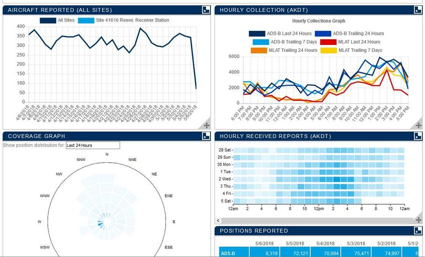
aircraft position and other data such as altitude and speed. The transmitted signals can be received by a ground
receiver as well as other aircraft. ADS-B currently supplements air traffic control radar for aircraft tracking and
allows pilots to be aware of and avoid other aircraft. ADS–B is automatic – requires no pilot intervention – and is
dependent – depends on the aircraft onboard navigation systems and air data sensors.

                                             Figure 2 ~ ADS-B functional diagram shows the three basic components –
                                             Global Satellite Navigation System (GNSS), aircraft equipped with flight data
                                             sensors and ADS-B transmitters and receivers, and ground station receivers.
                                             The aircraft systems depend on onboard sensors and automatically
                                             broadcast position and other flight information data. The data are processed
                                             by receivers to display aircraft positions on a map and provide alerts and
                                             other information to ground stations and other aircraft. Flight-Pi is an
                                             example of a ground station receiver. Image © 2018 W. Reeve

                                               3. Flight-Pi Description

Flight-Pi receives and processes ADS-B and transponder signals and sends the processed data to {FlightAware}
where it is shared with other users (figure 3). A map with aircraft data may be displayed on a local PC along with
numerous statistics associate with the specific PiAware installation (figure 4). Receivers in the area that receive,
process, and share the same flight data as Flight-Pi allow the positions of aircraft that are equipped with
transponders but not equipped with ADS-B to be computed. Flight-Pi operates from a nominal 12 Vdc power
supply and requires a local area network (LAN) and antenna connection (figure 5).

                                                                                                     Figure 3 ~ Block
                                                                                                     diagram of the
                                                                                                     Flight-Pi application.
                                                                                                     The only Raspberry
                                                                                                     Pi software required
                                                                                                     besides the
                                                                                                     operating systems
                                                                                                     are the PiAware
                                                                                                     software and a web
                                                                                                     browser. The
                                                                                                     PlanePlotter
                                                                                                     application shown
                                                                                                     here is optional.
                                                                                                     Image © 2018 W.
                                                                                                     Reeve

                 See last page for copyright and document information, File: Reeve_Flight-Pi.doc, Page 2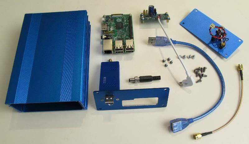
Figure 4.a ~ Web
                                                                                                    browser screenshot
                                                                                                    of PiAware map as
                                                                                                    well as tabulated
                                                                                                    aircraft data being
                                                                                                    received at
                                                                                                    Anchorage, Alaska
                                                                                                    early Saturday
                                                                                                    evening. The table
                                                                                                    may be turned off.
                                                                                                    This map is about 60
                                                                                                    nm across. Aircraft
                                                                                                    tracks are turned
                                                                                                    on. To access the
                                                                                                    map, the IP address
                                                                                                    of the Flight-Pi is
                                                                                                    entered in the
                                                                                                    browser.

                                                                                                    Figure 4.b ~ Web
                                                                                                    browser screenshot
                                                                                                    of PiAware statistics
                                                                                                    for my Flight-Pi
                                                                                                    installation. Only
                                                                                                    some of the
                                                                                                    statistics are shown
                                                                                                    here. The statistics
                                                                                                    are accessed
                                                                                                    through an
                                                                                                    individual
                                                                                                    FlightAware
                                                                                                    webpage assigned
                                                                                                    to that station.

                                                     Figure 5 ~ Flight-Pi interconnections. All components are enclosed
                                                     in an extruded aluminum enclosure, and all device interconnections
                                                     except the USB cable are internal. Image © 2018 W. Reeve

A working flight tracking system may be built by simply connecting the FlightAware receiver to a Raspberry Pi,
inserting a preprogrammed memory card with the PiAware software image and connecting 5 Vdc power, LAN
and antenna. Such a setup would be considered temporary because the components are exposed to damage or

                See last page for copyright and document information, File: Reeve_Flight-Pi.doc, Page 3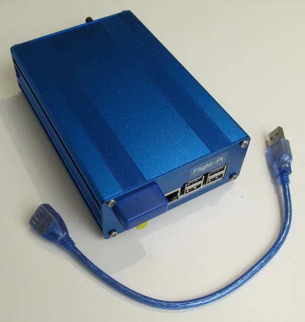
accidental disconnection. The Flight-Pi includes all components in an enclosure with a dc-dc converter so that
the system may be powered from a 12 Vdc station power supply. The package makes the system more
permanent, reliable and easier to physically manage.

Receiver: The FlightAware receiver is an RTL-dongle-type software defined radio (SDR) receiver that has been
optimized for reception of ADS-B signals at 1090 MHz (L-band). The receiver digitizes the radio frequency signals
and converts them to an in-phase and quadrature-phase (I/Q) digital bit stream that is processed and
demodulated by the software on the Raspberry Pi computer. The receiver version used here is the FlightAware
USB Pro Stick Plus (figure 6), which has a built-in bandpass filter to reduce interference from extraneous
transmissions. As of May 2018 the receiver costs about 19 USD and it is available in the USA through eBay and
Amazon. A version of the receiver, the FlightAware USB Pro Stick, is available without the internal filter for 18
USD but an external bandpass filter is recommended for use with that receiver. The receiver is powered through
the USB connection to the Raspberry Pi. A short USB-A extension cable is used on Flight-Pi to connect the
receiver to a Raspberry Pi USB port.

                                                      Figure 6 ~ FlightAware USB Pro Stick Plus receiver. The receiver is
                                                      powered by 5 Vdc through the USB connection on the left. The SMA
                                                      antenna connector is on the right. This version of the receiver has a
                                                      built-in bandpass filter to reduce interference. Principle dimensions
                                                      are 70 L x 30 W x 13 D mm. Image source: FlightAware

Raspberry Pi: While building this system I tried both the Raspberry Pi 2 model B (RPi2) and Raspberry Pi 3 model
B (RPi3) platforms. The RPi3 has built-in Wi-Fi capability (2.4 GHz); however, the built-in Wi-Fi will not work
when installed in the aluminum enclosure. A Wi-Fi USB dongle can be used in its place where wireless operation
is desired. I will refer to both platforms as RPi except where differentiation is needed. Both types use a micro-SD
memory card to store the operating system and application software.

Power supply: The power supply is based on a modular dc-dc converter that has an input range of 6.5 to 18 Vdc
and approximately 90% efficiency. The minimum input voltage is increased to 8 Vdc by the polarity guard diode
voltage drop plus a margin. The converter is mounted on a small PCB, which also includes a power input
connector, power output cable and an inductor and capacitors for filtering. Power is supplied through a 2.1 x 5.5
mm coaxial dc power jack (center positive).

Enclosure: The enclosure is the Box Enclosures B3-160. The Raspberry Pi Ethernet and USB connectors, receiver
USB connector and antenna are on the front panel and dc input connector, power switch and power indicating
LED are on the rear panel (figure 7).

Software: The PiAware software is a free download that must be installed on a micro-SD memory card. The
installation uses two partitions with a total requirement of about 4.8 GB. I used an 8 GB, Class 10 card but larger
and slower cards may be used. Once installed, the software is ready to use and no configuration is needed with
a wired Ethernet LAN. Configuring it for Wi-Fi operation requires a temporary wired LAN connection to access
and specify the Wi-Fi settings. PiAware is compatible with other ADS-B receivers but their implementation is
beyond the scope of this article.

                 See last page for copyright and document information, File: Reeve_Flight-Pi.doc, Page 4
Figure 7 ~ Front and rear end panels. Image © 2018 W. Reeve

                                                                                               4. Construction

Enclosure: The extruded aluminum enclosure includes two sheet aluminum end panels (figure 8). The front
panel requires cutouts for the RPi USB and Ethernet connectors, receiver USB connector and antenna connector.
The rear end panel requires cutouts for a power indicating LED, power toggle switch and coaxial dc power jack.
The enclosure body requires drilled holes for mounting the internal power supply and Raspberry Pi, both of
which are installed on 6 mm brass standoffs. The polarity guard diode and capacitors that are part of the input
filter for the dc-dc converter power supply are installed on the rear panel (figure 9).

               22.4                                                                                          21.2               20.0

                       14.0                                                                                                 Power           Ø 7.8
   12.25                                                                                              13.2                                               S/N FPxxx-2
                                                      17.0           Flight-Pi                                                                          DD MMM YYYY
                                                7.0          3.0
29.35                                                                                          30.2
                                                                                                                                                Ø 6.2
           Ø 0.25
                                                                                                                    +8 ... 16          ON
                                                                                                                      Vdc                      Ø 6.0
                                                                                        17.5

                      Antenna                                                           8.0

               22.4                                                53.5          15.0

                                                                                                                                       Figure 8 ~ Upper: Front and rear end panels
                                                                                                                                       require circular and rectangular cutouts. Lower:
                                                                                                                                       The RPi and power supply PCB are mounted to the
                                                                                                                                       bottom of the enclosure body with brass
                         CPS-1 Drill Template

                                                                                                                                       standoffs.

                                                                                                                                       I print paper templates from scaled drawings,
                                                                                                                                       tape them to the panels and body and mark with
                                                                                                                                       a center punch. After scribing the outline of the
                                                                                                                                       rectangular cutouts with a hobby knife, I drill pilot
                                                                                                                                       holes. The pilot holes are then enlarged as
                                                                                                                                       required for each cutout. The rectangular holes
                                                                                                                                       are finished to the outline with small files. Image
                                                                                                                                       © 2018 W. Reeve

                                                See last page for copyright and document information, File: Reeve_Flight-Pi.doc, Page 5
White USB cable w/
right-angle connector
Figure 9 ~ Power circuit wiring
Red: +5 V
Blk: Gnd
diagram. All components on the
5 Vdc, 1000 mA NC
right are installed on the rear
5
1
6
5 CPS-1 Mod 1
Shell
panel. LED (LED1) has a built-in
PP2:
PJ1
Insulating sleeve
current limiting/voltage
Micro-USB
Right-angle LED1
both leads dropping resistor for 12 V
K C1001
Center operation. C101 is used with L1
C101 D1 and C11 on the power supply
A
Install at IC5 with
SR10 P1 Top Insulating
sleeve + lead
PCB as a pi-filter for the input of
S05
text facing board Blk Red Gnd
the dc-dc converter. Image ©
S1
In Gnd Out
VIn Twist full length 2018 W. Reeve
Power supply: The main component of the internal power supply is a 10 W, 12 V nominal input, 5 V output dc-dc
converter and a printed circuit board. Also included is a PTC resettable fuse for overcurrent protection and
capacitor and inductor filter components, which together with the capacitors on the rear panel form a Pi input
filter for the dc-dc converter.
Bill of material: The BOM is straight-forward and requires only a few unique parts (table 1). Although certain
part numbers are called out, substitutions may be made that have equivalent voltage, current and power
ratings.
Table 1 ~ Flight-Pi material list (NPN: No Part Number)
Item Qty P/N Mfr or Vendor Description
1 1 RPi Raspberry Pi Raspberry Pi 2 model B (or Raspberry Pi 3 model B)
2 1 NPN Generic Micro-SD memory card, 8 GB, Class 10
3 1 NPN FlightAware FlightAware Pro Stick Plus USB Receiver
4 1 NPN RFSupplier Coaxial jumper cable, SMA-M to SMA-F bulkhead mount, 150 mm
5 1 NPN Generic USB-A extension cable, 150 mm
6 1 CPS-1 M1 Reeve Power supply printed circuit board, mod 1
7 1 22-23-2021 Molex Header, 2C, with friction lock
8 1 22-01-3027 Molex Wire mount housing, 2C, with friction lock and polarizing ribs
9 2 08-50-0114 Molex Contact, spring-type, 24-26 AWG
10 1 NPN Generic Micro-USB-B to blunt power cable, 150 mm
11 4 NPN Generic Rubber bumper feet, self-adhesive, 10 x 3 mm
12 1 B3-160xx Box Enclosures Enclosure, extruded aluminum, 160 x 109 x 45 mm (xx = color)
13 1 317228 Jameco Toggle switch, miniature, SPST
14 1 L722A Switchcraft DC coaxial power jack, locking, 2.1 x 5.5 mm
15 1 767K Switchcraft DC coaxial power plug, long barrel (locking), 2.1 x 5.5 mm
16 2 860020474014 Wurth Capacitor, 470 F, 25 V, electrolytic, 105 °C, 3.5 mm LS, C102, C11
17 3 NPN Generic Capacitor, 10 nF, 50 V, MLCC, 2.5 mm LS, C1001
18 1 AIAP-01-6R8K-T Abracon Inductor, 6.8 μH, 1.6 A, epoxy coated, L1
19 1 MF-R090 Bourns PTC resettable fuse, 900 mA, 60 V
20 1 SR10S05 XP Power Encapsulated power supply, 12 V:5V, 10 W
21 1 637183 Jameco LED, 12 V, Green, panel mount (with internal dropping resistor)
22 1 1N5819 Generic Schottky diode, 40 V, 1 A
23 2 WH24-xx NTE Hookup wire, stranded 7x32, 24 AWG, 300 V PVC, red and black
24 4 92005A116 McMaster Machine screw, M3 x 6 mm, phillips pan head
See last page for copyright and document information, File: Reeve_Flight-Pi.doc, Page 625 4 91106A122 McMaster Washer, internal star, 3 mm
26 4 92148A150 McMaster Washer, split lock, 3 mm
27 4 90591A250 McMaster Hex nut, M3
28 4 NPN Generic Hex standoff, male-female, M3 x 6 x 6 mm, brass
29 4 92005A066 McMaster Machine screw, phillips pan head, M2.5 x 6 mm
30 4 91106A150 McMaster Washer, internal star, 2.5 mm
31 4 92148A070 McMaster Washer, split lock, 2.5 M
32 4 90591A270 McMaster Hex nut, M2.5
33 4 NPN Generic Hex standoff, male-female, M2.5 x 6 x 6 mm, brass
Assembly: The components are built into subassemblies – power supply and front and rear panels – and, with
the RPi, are installed on the enclosure body (figure 10). The receiver is mounted on the front panel along with an
SMA-F bulkhead mount antenna connector.
Figure 10 ~ Collection of prototype Flight-Pi
components. The RPi is top-middle of image and
the fully assembled power supply PCB is just to
the right of it. The front panel (lower-middle) has
the receiver fastened to it and the rear panel
(upper-right) has power wiring installed. The
prototype is shown here with a coaxial jumper
cable (lower-right corner) that uses SMA-M
connectors at both ends and connects to a
bulkhead mount SMA-F to SMA-F coupler on the
front panel. The BOM eliminates the coupler and
uses a jumper cable with SMA-M to SMA-F
bulkhead mount connectors. Image © 2018 W.
Reeve
The receiver is not designed for panel mounting but I adapted it. The receiver has a small, raised plastic
reinforcement ridge around the USB connector. The front panel cutout shown on the drawings matches this
reinforced area allowing the receiver to be epoxied in place with clearance for the connector. I used two small
screws to add support, although they probably are not necessary. For these screws I carefully drilled two #50
holes through the panel and into the receiver plastic housing and then enlarged the panel holes to #43. These
holes were placed to ensure that drilling would clear the receiver PCB inside the plastic enclosure but I was
careful to prevent the drill bit from penetrating the housing. I inserted two 2-56 flat-head screws just long
enough to fit the panel and plastic housing and added a small amount of adhesive to the threads. To complete
the front panel subassembly after the receiver was mounted, I added a coaxial jumper cable from the receiver
RF input connector to the front panel. Prior to installing the RPi in the enclosure, load the PiAware software on a
memory card as described in the next section and insert into the card slot on the RPi PCB.
The power switch, LED and coaxial power jack are mounted and wired. The rear panel includes a connectorized
2-conductor pigtail, which connects to the power supply mounted in the enclosure body. After the two panels
are finished and the power supply and RPi are connected and mounted in the enclosure body, the panels may be
installed. The first time the panels are mounted on the body, the screws cut their own threads. This is made
easier with a very small amount of thread-cutting oil on the screws before inserting them. I withdraw the screws
to clean any left-over oil and metal fragments and then reinsert.
See last page for copyright and document information, File: Reeve_Flight-Pi.doc, Page 75. Setup
Detailed information on installing the PiAware software on a memory card is available at {PiAware}. Where a
wired LAN connection is used, no additional setup is needed (Wi-Fi is discussed at the end of this section). With
the Flight-Pi connected to the antenna, LAN and power, the PiAware application software automatically loads
when power is applied and obtains a free account from {FlightAware}. Allow a couple minutes for the RPi to
boot. If after obtaining the FlightAware account a new image is loaded on the RPi memory card, PiAware will
automatically obtain a new but different account. This could lead to multiple accounts assigned to one user, but
it can be avoided as explained later. If the extra accounts go unused for a month, they will disappear and any
statistics associated with them will be lost.
Flight-Pi management: Flight-Pi is operated in a “headless” mode in which no keyboard, mouse or display is
connected. All provisioning is through a LAN connected PC that is running a terminal emulator program such as
PuTTY or Tera Term. Refer to {RPiBasic} for details. First, determine the IP address of the RPi. The IP address may
be determined with the free NetScan, AngryIP or Advanced IP programs running on a Windows PC. The address
also may be obtained from the LAN router network map, although I find a dedicated program is much better.
Now, access Flight-Pi from the PC running PuTTY or Tera Term and login. The default user and password are:
Default user: pi
Default password: flightaware
Password: After logging into the RPi be sure to change the default password. To change the password, follow the
on-screen prompts after entering:
passwd
Status: Check the status of PiAware by entering:
sudo piaware-status
If necessary PiAware may be restarted if there had been a problem or configuration change. To restart enter:
sudo systemctl restart piaware
The CPU load can be determined from the top command (figure 11). Top is a built-in tool that shows all running
processes and is similar in function to the Windows Task Manager. At the console prompt enter:
top
See last page for copyright and document information, File: Reeve_Flight-Pi.doc, Page 8Figure 11 ~ PuTTY screenshot shows the results of the top
command. As indicated just below the dark column
header, the dump1090 application (program ID 842), which
processes the signals from the ADS-B receiver, places the
highest load, in this case about 34%.
To return to the prompt, enter q or CTRL-C.
The SoC (System on a Chip, or CPU) internal temperature is measured by entering the following string at the
PuTTY command line prompt:
sudo vcgencmd measure_temp && date
The appended date command (&& date) helps to track the temperature over time. The indicated SoC
temperature will depend on the ambient temperature but should be below approximately 50 °C.
After Flight-Pi is in service, its unique FlightAware account number, called feeder_id, should be determined and
saved for future reference. It will be needed to prevent extra accounts from being assigned and statistics lost in
case the PiAware image has to be reinstalled on the RPi memory card.
To find the assigned feeder_id, use WinSCP and go to the /var/cache/piaware directory. Open the file labeled
feeder_id using the WinSCP editor. The feeder ID is a 32 hex digit string of the form:
hhhhhhhh-hhhh-hhhh-hhhh-hhhhhhhhhhhh.
Alternately, the ID also can be found on the user’s online FlightAware account (view the My ADS-B tab and look
for the Unique Identifier field in the Site Information section) or it may be determined from the PuTTY or Tera
Term console. At the prompt enter:
sudo nano /var/cache/piaware/feeder_id
If, in the future, it is necessary to reload the PiAware image from scratch to the RPi memory card, a new
FlightAware account is automatically assigned when the Flight-Pi is reconnected. To avoid this and retain the
original account and associated statistics, it is necessary to slightly modify the PiAware configuration file before
first powering the Flight-Pi with the new image. To load a new image, the Flight-Pi enclosure needs to be opened
and the RPi removed for access to the memory card slot. Remove the memory card from the RPi and insert in a
card reader/writer device then connect the reader/writer to a PC.
After loading the new image on the memory card but before removing it from the PC, open the piaware-
config.txt file on the card using a text editor such as NotePad or NotePad++. Scroll down to the Receiver
Configuration section and add the text feeder_id and the ID determined previously, separated by one space
(figure 12). Save the file to the memory card, eject it from the PC and install it in the Flight-Pi. Now, when the
See last page for copyright and document information, File: Reeve_Flight-Pi.doc, Page 9Flight-Pi is started with the new image, it will use the existing account. After the new PiAware image has
connected to FlightAware, the ID will be inserted automatically in the /var/cache/piaware directory and the
feeder_id entry in the configuration file may be commented out with the # character.
Figure 12 ~ NotePad screenshot shows the changes to the
PiAware configuration file piaware-config.txt. Add
the two lines shown bottom-left at any convenient location
in the file. One line is commented with the # character and
has the existing FlightAware site number for reference, and
the other line has the 32 digit feeder_id string associated
with the existing FlightAware account. The account
number is a series of hex characters shown here as h,
where h = 0 to 9 and a to f.
Timing: Accurate timing is required for multi-lateralization (Mlat) computations. Accurate receiver station
position also is required. The PiAware software uses Coordinated Universal Time (UTC) as the time reference
and the Network Time Protocol (NTP) for timekeeping. The default NTP configuration file in PiAware uses four
time server pools and can be improved by using specific geographically nearby time servers. The best timing is
obtained from local time servers (such as, for example, {GpsNtp-Pi}) with time server pools as backup. The NTP
chooses the best time server from all of those listed in the NTP configuration file – usually a local time server if
one is available.
The NTP configuration file can be edited to change, delete or add time servers:
sudo nano /etc/ntp.conf
Scroll down to the server pools (server x.debian.pool.ntp.org iburst where x is 0 to 3) and change each of
the four from debian to use the pool of choice (figure 13). Users in the USA should select the US pools as shown
below (the first three lines beginning with the # character are existing comments). Users in other countries can
select a regional, continental or country pool from {NTPPool}.
# pool.ntp.org maps to about 1000 low-stratum NTP servers. Your server will
# pick a different set every time it starts up. Please consider joining the
# pool:
server 0.us.pool.ntp.org iburst
server 1.us.pool.ntp.org iburst
server 2.us.pool.ntp.org iburst
server 3.us.pool.ntp.org iburst
If local time servers are available, they should be added to the configuration file, one on each line before or after
the server pools (their actual location in the configuration file does not matter but it is convenient to have them
near the pools list). The example below shows the IP addresses of two local time servers in my network
(substitute the addresses of your own time servers).
# local NTP servers
server 10.0.0.131 iburst
server 10.0.0.143 iburst
See last page for copyright and document information, File: Reeve_Flight-Pi.doc, Page 10Figure 13 ~ PuTTY screenshot shows the NTP configuration
file. Changes have been made to the time server pools, and
local time servers have been added as described in the
text.
When finished editing the NTP configuration file, save the changes by entering CTRL-X, Y, Enter. After saving the
changes, restart NTP:
sudo service ntp restart
Wait a few minutes and then check the time servers with the NTP query tool (figure 14):
ntpq –crv –p
Figure 14 ~ PuTTY screenshot shows the results of an NTP
query. This example shows four pools and two local
time servers and other details. The symbols next to
the servers are:
* = current time source
# = source selected, distance exceeds maximum value
o = source selected, Pulse Per Second (PPS) used
+ = source selected, included in final set
x = source false ticker
. = source selected from end of candidate list
– = source discarded by cluster algorithm
blank = source discarded high stratum, failed sanity
The setup described above uses a wired LAN connection. If a Wi-Fi (also called WLAN) connection is desired,
follow the description at {RPiWLAN}.
6. RF Notes
Low noise amplifier: Where the system layout requires long cable runs from the antenna to receiver, an LNA can
be used to improve the system noise figure. For example, 30 m of LMR-400 (10 mm diameter) coaxial cable has
a loss of 4.7 dB (including connectors) at 1090 MHz. The receiver noise figure is around 3 to 4 dB, so this cable
would increase the system noise figure to 8 or 9 dB. A higher noise figure indicates lower sensitivity; therefore,
the receiver range will be significantly reduced. An LNA located close to the antenna will improve the system
noise figure, but it may be necessary to reduce the receiver gain or to insert an attenuator between the LNA and
receiver to prevent overload. LNAs with a built-in bandpass filter for 1090 MHz and bias-tee powering or
external powering are available from {Uputronics}.
See last page for copyright and document information, File: Reeve_Flight-Pi.doc, Page 11Antenna: For the best performance, use a high-gain, omni-directional antenna mounted as high as possible.
Foliage and building loss at L-band can be significant, so the antenna should be clear of trees and obstructions
and have a clear view of the sky in all directions if at all possible. The range of a system with a good antenna and
no obstructions or foliage can approach 200 nm. An example of a purpose-built ADS-B antenna is the DPD
Productions ADS-B omni-directional, collinear dipole antenna, which has an advertised gain of 9.0 dBi {DPD}. A
1/4-wavelength indoor whip antenna placed near a window may be used to confirm system operation but is not
recommended for a permanent installation because of low overall performance.
Coaxial cable and connectors: Use only high quality coaxial cable and connectors for all RF connections. RG-58
and equivalent cables introduce high loss at 1090 MHz and are not recommended in lengths > 10 m unless a low
noise amplifier is used at the antenna. Never use push-on (tool-less) RF connectors.
6. Weblinks and References
{ADS-B} https://en.wikipedia.org/wiki/Automatic_dependent_surveillance_%E2%80%93_broadcast
{DPD} http://www.dpdproductions.com/page_vhf_air.html#adsbout
{FlightAware} https://flightaware.com/adsb/
{GpsNtp-Pi} http://www.reeve.com/RadioScience/Raspberry%20Pi/GpsNtp-Pi.htm
{NTPPool} https://support.ntp.org/bin/view/Servers/NTPPoolServers
{PiAware} https://flightaware.com/adsb/piaware/
{RPiBasic} http://www.reeve.com/Documents/Articles%20Papers/Reeve_RPi_BasicSetup.pdf
{RPIWLAN} http://www.reeve.com/Documents/Articles%20Papers/Reeve_RPi_WLANSetup.pdf
{Uputronics} https://store.uputronics.com/index.php?route=product/product&path=59&product_id=50
Author - Whitham Reeve is a contributing editor for the SARA journal, Radio Astronomy.
He obtained B.S. and M.S. degrees in Electrical Engineering at University of Alaska
Fairbanks, USA. He worked as an engineer and engineering firm owner/operator in the
airline and telecommunications industries for more than 40 years and now manufactures
electronic equipment used in radio astronomy. He has lived in Anchorage, Alaska his
entire life.
See last page for copyright and document information, File: Reeve_Flight-Pi.doc, Page 12Document information
Author: Whitham D. Reeve
Copyright: © 2018 W. Reeve
Revisions: 0.0 (Draft started 28 Feb 2018)
0.1 (1st draft completed, 03 Mar 2018)
0.2 (Revised time server details and cleaned up, 05 Mar 2018)
0.3 (Added Mlat position requirement, 07 Mar 2018)
0.4 (Added PiAware images and add’l cleanup prior to distribution, 06 May 2018)
0.5 (Distribution, 07 May 2018)
Word count: 4511
File size: 6495232
See last page for copyright and document information, File: Reeve_Flight-Pi.doc, Page 13You can also read