PROPANE WATER CHILLERS HEAT PUMPS - R290 - Skadec

Page created by Aaron Burton
 
CONTINUE READING
PROPANE WATER CHILLERS HEAT PUMPS - R290 - Skadec
PROPANE
WATER CHILLERS
HEAT PUMPS

  R290
  ENVIRONMENTALLY
  FRIENDLY
PROPANE WATER CHILLERS HEAT PUMPS - R290 - Skadec
CONTENTS

       SKADEC products _______________________________________________________ 3
       Propane (R290) water chillers and heat pumps _________________________________ 4
       F-gas regulation _________________________________________________________ 6
       Intelligent machine control _________________________________________________ 8
       SKADEC remote maintenance _____________________________________________ 10
       R290 product line ______________________________________________________ 11
       • R290 water chillers with free cooling and special solutions _____________________ 12
       • R290 heat pumps with performance data __________________________________ 14
       • R290 water chillers with performance data _________________________________ 16
         Air conditioning application VCG ________________________________________ 18
         Air conditioning application VCGV________________________________________ 19
         Cold storage and supermarket VCG_______________________________________ 20
         Cold storage and supermarket VCGV______________________________________ 21
         Dimensions _________________________________________________________ 22

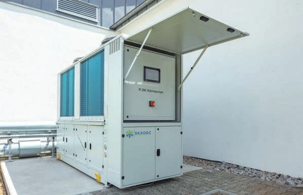
Example propane heat pump

2     PROPANE WATER C HILLERS
PROPANE WATER CHILLERS HEAT PUMPS - R290 - Skadec
SKADEC PRODUCTS

SKADEC is your strong partner when it comes to natural refriger-
ants. Our innovative chillers and heat pumps are operated with the
natural refrigerant propane (R290). They are an environmentally
friendly and energy efficient solution and a sustainable alterna-
tive to conventional chillers and heat pumps operated with HFC
refrigerants. All chillers are optionally available with a free cooling
coil. At low ambient temperatures, the free cooling replaces the
compression refrigeration technology, resulting in a high increase        BAFA eligibility of water chillers and
in energy efficiency.                                                     heat pumps

SKADEC has many years of experience and expertise in using the            Water chillers and heat pumps operated with the natural,
natural refrigerant propane. Our service and maintenance staff            halogen-free propane refrigerant are eligible in the appropriate
are competent in the use of natural refrigerants.                         configuration.

Already today we have realised numerous projects with propane             The German Federal Office for Economic Affairs and Export Control
chillers. The propane chiller and heat pump product line is devel-        (BAFA) hathas launched a federal funding program to increase en-
oped in collaboration with experienced engineers and technicians.         ergy efficiency in companies. In this program, a subsidy for efficient
Proximity to the end customer enables us to offer market-oriented         refrigeration/air conditioning systems and free cooling is available.
overall solutions. Experiences from production, assembly and ser-         The chillers and heat pumps have to run at least 5 years on Ger-
vice are continuously incorporated into the further development.          man federal territory without discontinuation or sale.

                                                                          We would be happy to advice you on eligible configurations
                                                                          and on the application for funding.
Programmable logic control PLC
                                                                          Just contact us.
As a standard, we offer you an individually adaptable, industry-
standard solution with very high operational reliability with our
in-house developed PLC-based control programs.
                                                                               CE Declaration of Conformity and
                                                                               Certifications

                                                                               All appliances offered are supplied with a CE Declara-
                                                                               tion of Conformity.

                                                                               Production is certified according to Module A2, B, C2
                                                                               and D of the Pressure Equipment Directive 2014/68 EU
                                                                               and to ISO 9001.

                                                                               Standards and Guidelines:

                                                                               • DIN EN 378
                                                                               • Pressure Equipment Directive
                                                                               • Low Voltage Directive
                                                                               • Machine Directive
                                                                               • Electromagnetic Compatibility

                                                                                                            PROPANE WATER C HILLERS           3
PROPANE WATER CHILLERS HEAT PUMPS - R290 - Skadec
PROPANE (R290) WATER CHILLERS
AND HEAT PUMPS

Sustainability, energy efficiency, redundancy, plant safety and life-cycle
costs are the criteria taken into account for the development of our future-
proof water chillers and heat pumps. Wherever possible, we already
rely on the use of natural refrigerants that are proven to be efficient, safe,
environmentally friendly and future-proof for the respective application.
Water chillers and heat pumps are designed in such a way that the
refrigerant charge is low and high plant availability is ensured. An exten-
sive safety concept ensures safe operation of the systems.

The use of natural refrigerants, especially hydrocarbons such as R290,
is particularly suitable in air-cooled water chillers and heat pumps
for outdoor installation. Legal restrictions on the filling quantity and
EX protection requirements to be observed in individual cases can be
implemented well here. The refrigerant neither has an ozone depletion            Advantages of hydrocarbons
potential (ODP = 0), nor a significant direct greenhouse effect (Global
Warming Potential –GWP = 3) and also has very high coefficients of               • Environmentally friendly operation of the system due
performance. As a result, the life cycle costs are significantly lower com-         to high system efficiency, high coefficients of perfor-
pared to comparable systems with conventional HFC refrigerants.                     mance.
                                                                                 • GWP = 3 (global warming potential) close to zero,
For service technicians, the natural refrigerant propane (R290) is easy             the gas also is part of the atmosphere!
to handle. It is characterised by similar pressures as conventional HFC          • No regulation by the F-gas regulation, natural refrig-
refrigerants.                                                                       erant!
                                                                                 • Even a future tightening of the F-gas regulation will
                                                                                    not affect propane (R290).
                                                                                 • Low pressure, less than 28 bar.
                                                                                 • Safer operation of the system even at high outside
                                                                                    temperatures.
                                                                                 • Efficient operation in summer and winter.

4      PROPANE WATER C HILLERS
PROPANE WATER CHILLERS HEAT PUMPS - R290 - Skadec
FUTURE-PROOF – OUR SUSTAINABLE CONCEPT FOR THE
ENVIRONMENT AND YOUR COMPANY

Fulfilling future bans and market regulations today.

Direct and indirect emissions of water chillers and heat pumps

The emissions of liquid chillers and heat pumps are composed of direct and
indirect emissions. Direct emissions are caused by leaks and the escape of
refrigerant into the atmosphere. Choosing the natural refrigerant R290 with
                                                                                                     R290
                                                                                                     ENVIRONMENTALLY
                                                                                                     FRIENDLY
a very low GWP = 3 (global warming potential), leads to avoiding notable
direct emissions. The commonly used refrigerants R410A (GWP = 2090) and
R134a (GWP = 1430) in comparison are damaging to the climate.

Increasing the energy efficiency of the systems influences the indirect emis-
sions (current consumption). The efficiency-optimized generous design of the
main components ensures high energy efficiency ratios (EER). As a standard,
electronic injectors are used. A generously dimensioned condenser surface
ensures a low condensation temperature.

                                               »                     Where will refrigeration technology be in ten years?

                                                                     Quotation of the German Federal Environment Agency
                                                                     on the use of HFC refrigerants:

                                                                     “For new systems, the Federal Environment Agency does not
                                                                     consider these refrigerants [HFKWs] as trendsetting, as long
                                                                     -term safe alternatives are available with halogen-free, natural
                                                                     refrigerants such asCO₂, NH₃ or hydrocarbons.”

                                                                                                    PROPANE WATER C HILLERS         5
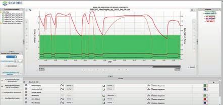
PROPANE WATER CHILLERS HEAT PUMPS - R290 - Skadec
F-GAS REGULATION*

The use of fluorinated greenhouse gases is regulated by the European Parliament in the F-gas Regula-
tion (EU) No. 517/2014 and Regulation 2006/40/EG. The F-gas Regulation, amended in 2014, came
into force on 1st January 2015, significantly tightening the previously F-gas Regulation No. 842/2006
from 2007.
The objective of the new F-gas Regulation is to contribute to a reduction in the amount of F-gases emit-
ted in the EU in “tonnes of CO2 equivalents” of 70 % by the year 2030 compared to the level in 1990.

                                                    The quantities of HFCs available on the market will be reduced in stages.

                                                    Fixed initial quantity
                                            100 %
                                                              93
    Quantity calculated in CO₂ equivalent

                                             90 %
                                                                                    Fixed initial quantity is gradually reduced,
                                             80 %
                                                                                    but not reduced to zero.(“Phase down”).
                                             70 %
                                             60 %                            63
                                             50 %
                                                                                           45
                                             40 %
                                             30 %                                                            31
                                             20 %                                                                                  24
                                                                                                                                           21
                                             10 %
                                              0%
                                               2015         2017         2019     2021      2023        2025         2027          2029   2031
                                                                                             Year

Reducing the quantity of HFCs available on the market and introducing additional HFC refrigerant
taxes from 2015 onwards will inevitably lead to supply bottlenecks, increasing refrigerant prices, push-
ing HFC refrigerants out of the market in several stages. This should lead to a change in attitude of

                                                                                   »
operators of chillers, encouraging them to invest in new technologies using future-proof refrigerants.

*Contents page 6-7 Source: Federal Environment Agency
  (Brochure in German: “Hauptsache KALT?”)

                                                                                                               Statement by the German Federal Environment Agency:

                                                                                                               “Due to the quota system introduced in the EU, a significant in-
                                                                                                               crease in the price of R404A and other refrigerants with a high
                                                                                                               GWP is to be expected.”

                                                                                                               “Whether this will lead to a shortage of refrigerants within the next
                                                                                                               ten years, remains to be seen.”

6                                           PROPANE WATER C HILLERS
PROPANE WATER CHILLERS HEAT PUMPS - R290 - Skadec
Following entry into force of the new regulation, as from 01.01.2020 new systems may only be filled with
refrigerants with a GWP lower than 2500. Applications with cooling temperatures below -50 °C are not
affected. A further tightening of the regulations for new plant will comes into force on 01.01.2022. From
then on, multipurpose centralised refrigeration systems for commercial use with a capacity of more than
40 kW may only be marketed with a refrigerant with GWP  1.500
                                          1.430   1.397
 1.500

 1.000                                                                         Further tightening
                                                           675                 for CM with GWP >150
                                                                               to be expected
  500
                                                                     6            3              1     0
    0
                                                                                                                 see Bitzer refrigeration report
           R404A      R410A       R407F   R134a   R449A    R32    R1234ze      R290           R744    R717

   The European Parliament is already discussing a further tightening of the
   F-gas Regulation (EU) No. 517/2014 leading to further CO2 reductions.
   A reduction in emissions of 80 to 95% by the year 2050 is currently be-
   ing discussed. Thus, in the long term, only refrigerants with a GWP
PROPANE WATER CHILLERS HEAT PUMPS - R290 - Skadec
INTELLIGENT MACHINE CONTROL

As control systems we use the freely programmable controllers. They are ideally suited for incorporating our many
years of experience in refrigeration and air-conditioning technology into our specially developed control algo-
rithms. In the design of our control programs, the main focus of our in-house programming department is on user-
friendliness, high availability as well as the efficiency of the systems..

Visualisation – Everything at a glance

                                                                                    The schematic representation of the
                                                                                    system shows all important process
                                                                                    data at a glance.

                                                                                    Detailed information about each ac-
                                                                                    tuator can be found on its information
                                                                                    screen.

                                                                                    Malfunctions or irregularities are high-
                                                                                    lighted in colour directly on the respec-
                                                                                    tive system component and in full text
                                                                                    in the alarm list. The intuitive display
                                                                                    concept ensures easy user-machine
                                                                                    interaction.

8      PROPANE WATER C HILLERS
PROPANE WATER CHILLERS HEAT PUMPS - R290 - Skadec
Control system

The heart of the machine control system is the control algorithm which ensures efficient and trouble-free opera-
tion of the system. Thanks to “condition monitoring”, the constant monitoring and analysis of all components and
process data, faults are detected as soon as they arise. As a result, for example, maintenance can be planned in
advance. However, should there be any irregularities or malfunctions, the machine responds autonomously and
provides the maximum possible power during emergency operation, despite any impairment.

Integration and communication

Thanks to the implementation of various bus interfaces, the systems can be easily integrated into existing processes.
These interfaces include among others Industrial Ethernet, Profibus-DP, Modbus-RTU, Modbus-TCP/IP and CANopen.

Data logger / Data plotter

Recording and analysis of a wide range of process data is becoming increasingly important. For this purpose,
our controller provides the user with a freely configurable data logger. The relevant data can be easily selected
via process visualisation. The controller automatically saves the data as a *.csv file on an SD memory card.
When required, the data can also be sent to a server. To be able to conveniently analyse the sometimes large
amounts of data, the controller additionally includes a data plotter which converts the recorded data into mean-
ingful line graphs. It is also possible to save the graphs as *.jpg, *.png or *.csv files.

                                                                                                         PROPANE WATER C HILLERS   9
SKADEC REMOTE MAINTENANCE

The powerful programmable logic controllers (PLC) of the series PFC with the in-house SKADEC chiller
software are IP capable as standard and provided with a web server for process and data visualisation.

Thanks to the use of HTML5, the visualisation can be operated and displayed with all popular end
devices such as smartphones, tablets and PCs using HTML5-capable web browsers (Microsoft Edge,
Google Chrome, Mozilla Firefox, Apple Safari, etc.).

To access the machine control outside the intranet, a secured connection can be used via a VPN router,
permitting remote monitoring, remote maintenance, troubleshooting, alarm reporting as well as long-term
process analysis and process optimisation. The router is conform to ISO27002, IEC62443-2-4, NIST Cy-
ber Security Framework 1.0, BSI TR-02102-1 & TR-02102-2 (German Federal Office for IT safety).

Communication

The VPN router can be connected to the Internet via Ethernet (Standard RJ-45), WLAN or the mobile
network.

                                     HTTPS

                                          VPN                                     VPN

10     PROPANE WATER C HILLERS
R290 PRODUCT LINE
EFFICIENT, SUSTAINABLE, QUIET AND SAFE

Production in accordance with the Pressure Equipment Directive
and European Safety Standard DIN EN 378

                    R290 WATER CHILLERS WITH FREE COOLING
                    AND SPECIAL SOLUTIONS                                12 – 13

                    R290 HEAT PUMPS
                    WITH PERFORMANCE DATA                                14 – 15

                    R290 WATER CHILLERS
                    WITH PERFORMANCE DATA                                16 – 17

                                                       PROPANE WATER C HILLERS   11
R290 WATER CHILLERS WITH FREE COOLING
AND SPECIAL SOLUTIONS

                                                                                           Special systems

                                                                                           • Individual programming
                                                                                           • High demands regarding noise emission
                                                                                           • Limited space
                                                                                           • Highly efficient systems
                                                                                           • Flexible machine configuration
                                                                                           • High/low ambient temperatures

                                                                                           High product standard

                                                                                           • Use of German-made components
                                                                                           • Programmable logic control (PLC) with 7" touch
                                                                                              screen
                                                                                           • Inverter for power regulation of the compressors
                                                                                           • EC fans
On request BAFA-eligible                                                                   • Optional: Live COP/EER (Accessories* required)
system configuration.

Propane (R290) water chillers are available in a wide range of capacities to satisfy specific process requirements
and environmental conditions. The machine design is individually adapted to the customer’s requirements. The main
focus may be on plant efficiency or redundancy, quiet operation or cost criteria. All machines are equipped with the
programmable logic controller developed in-house. This controller, which has been specially developed with opera-
tional safety in mind, ensures flexibility that was hitherto not possible.

Flexible production allows us to respond individually to customer requirements with tailor-made equipment.

                                           Air-cooled R290 water chillers

     100                            400                                        800                                       1.200 kW

Accessories – energy efficiency increase      Accessories – general                                   Accessories – electronics and monitoring
• Inverter control of compressors             • “low-noise” version                                   • Remote maintenance (Ethernet, W-LAN, UMTS)
• Inverter technology for pumps               • Shell & tube heat exchanger                           • Modbus RS485/ Modbus TCP, Profibus, Profinet
• EC fans                                     • Partial heat recovery/full heat recovery              • 10" touch screen
• Fan speed control                           • Spring anti vibration mounts                          • Energy meter*
                                                                                                      • Electronic flow monitor*

12       R 290 WATER C HILLERS WITH FREE COOLING AND SPEC IAL SOLUTIONS
Free cooling
All water chillers are optionally available with a free-cooling register arranged hydraulically in series.
Free cooling is used when there is a year-round demand for cooling in combination with higher system
temperatures. The use of sliding free cooling already permits in the transitional period mixed operation
of mechanical and free cooling, thereby greatly increasing the energy efficiency of the system.

Advantages
• Cooling without cold compression
• Short amortisation period of the additional investment
• Great reduction in CO2 emissions
• BAFA bonus funding possible (+30% above basic funding)

Air conditioning application
Propane water chillers in combination with a water or cooling brine
circuit are ideally suited for air conditioning of industrial or office build-
ings. High requirements for energy efficiency and noise protection
must be taken into account.

Process cooling
Operational safety and redundancy are the focus of product develop-
ment of propane chillers for process cooling. The application of free
cooling is used for appropriate system temperatures.

Cold storage and supermarkets
Propane chillers can be specially tailored for use in supermarkets and
for the storage of refrigerated goods such as fruit and vegetables.
Optimisation of energy costs while reducing dehumidification of re-
frigerated goods is becoming increasingly attractive to operators.

                                                                                                       Optionally separate hydraulic module

Optionally integrated hydraulic module

Single or double pump (inverter or standard), safety valve, water drain valve, water pressure gauge,
flow monitor, integrated buffer tank (depending on model), expansion tank and shut-off valve.

                                                                   R 290 WATER C HILLERS WITH FREE COOLING AND SPEC IAL SOLUTIONS             13
R290 HEAT PUMPS

                                                                                            Special systems

                                                                                            • Individual programming
                                                                                            • High demand regarding noise level
                                                                                            • Limited space
                                                                                            • Highly efficient systems
                                                                                            • Flexible heat pump configurations
                                                                                            • High/low ambient temperatures

                                                                                            High product standard

                                                                                            • Optimised design for heating operation
                                                                                            • Heat pump control algorithm developed in-house
                                                                                            • Use of German-made components
                                                                                            • Programmable logic control (PLC) with 7" touch
                                                                                               screen
                                                                                            • Inverter for power regulation of the compressors
                                                                                            • EC fans
                                                                                            • Optional: Live COP/EER (Accessories* required)
Condensation water drains off easily!

On request BAFA eligible
system configuration.

Air-cooled propane heat pumps for cooling and heating with the secondary medium water or brine are available in
a wide range of performance classes. Propane heat pumps are equipped with several refrigeration circuits, so that a
small amount of refrigerant is sufficient. Furthermore, refrigeration system redundancy is assured. In areas with strict
noise level regulations, the heat pumps are provided with large condenser surfaces, slow-moving fans and closed
compressor chambers. A comprehensive safety concept ensures safe operation of the systems. All heat pumps can
be supplied with the in-house developed, programmable logic controller. This controller, which has been specially
developed with operational safety in mind, affords great flexibility and can be integrated seamlessly into the existing
building control system.

Accessories – energy efficiency increase      Accessories – general                                   Accessories – electronics and monitoring
• Inverter control of compressors              • “low-noise” version                                   • Remote maintenance (Ethernet, W-LAN, UMTS)
• Inverter technology for pumps                • Shell & tube heat exchanger                           • Modbus RS485/ Modbus TCP, Profibus, Profinet
• EC fans                                      • Partial heat recovery/full heat recovery              • 10" touch screen
• Fan speed control                            • Spring anti vibration mounts                          • Energy meter*
                                                                                                       • Electronic flow monitor*

14       R 290 HE AT PUMPS
R290 Heat pumps CH and CW
Performance data for cooling and heating operation
                                                              CH-                CH-           CH-                CH-                CW-               CW-              CW-
  Heat pump for air conditioning                           CR11140IHP         CR22136IHP    CR22140IHP         CR22150IHP         CR22152IHP        CR33152IHP       CR44152IHP
  Cooling capacity                                 kW          38                52             76.1               145.9             171.8               257.7          343.6
  Power consumption for cooling                    kW         10.6               14.8           21.3               38.7              45.6                68.4            91.1
  Power consumption for cooling                     A         18.82             26.83           37.64              68.38             83.34              125.01         166.68
  Mass flow rate of refrigerant for cooling       kg/h        369.8             253.1           369.8              707.6             834.2               834.2          834.2
  EER                                                         3.58               3.52           3.58               3.77              3.77                3.77           3.77
  Heating capacity                                 kW         42.5               58.3            85                160.3             189.4               284.2          378.9

                                                                                                                                                                                      R290 Heat pumps CH and CW
  Power consumption for heating                    kW         11.2               15.5           22.3               40.5              40.8                61.25           81.7
  Current consumption for heating                   A         19.61             27.87           39.23              71.13             86.39              129.59         172.79
  Mass flow rate of refrigerant for heating       kg/h        328               223.3           328                626.5             740.8               740.8         740.79
  COP                                                         3.81               3.76           3.81                3.96             4.64                4.64           4.64
  Maximum current consumption                       A         20.2               40.4           27.2                74.4              88                  132            176
  Maximum starting current without inverter         A         82.4              102.6           75.8               134.2              169                 213            257
  Sound pressure level in 10 m on request         dB(A)        ––                ––              ––                  ––                ––                  ––             ––
  Device data
  Refrigerant                                     Type                                                             R290
  Power supply                                  Ph/V/Hz                                                       3/400V/50 Hz
  Number of compressors                             n           1                                         2                                                3              4
  Number of circuits                                n           1                                         2                                                3              4
  Capacity steps                                    –                                                         Stepless Inverter
  Semi-hermetic reciprocating compressor
  Max current consumption compressor                A         20.2               13.6           20.2                37.2              44                  44             44
                                                                                                                                   125.0 A Y /         125.0 A Y /    125.0 A Y /
  Max. inrush current                               A         82.4               62.2           82.4              97.0 A Y         211.0 A YY          211.0 A YY     211.0 A YY
  Max. power consumption                           kW         11.3               7.6            11.3                 21                25                  25             25
  Axial fans
  Number of fans                                    n           1                 2               2                  4                 4                   6              8
  Airflow fans                                    m³/h       15810              31620          31620              63240             63240               94860          126480
  Power consumption fans                           kW         1.85               3.7             3.7                7.4               7.4                 11.1          14.8
  Max. current consumption fans                     A         2.85               5.7             5.7                11.4              11.4                17.1          22.8
  Plate heat exchanger
  Flow rate of medium for cooling                 m³/h         6.4               9.7            14.14              27.09             31.93               47.88          63.84
  Flow rate of medium for heating                 m³/h        7.04              11.28          14.44               27.49             32.5                48.75           65
  Pressure drop                                    kPa        14.48             14.41           14.61              17.75             19.72               49.52          49.52
  Volume                                            L         8.99              12.82           19.01              34.92             46.02               54.54          72.72
  Optionally integrated hydraulic module
  Expansion vessel                                dm³          25                35              35                  50               50                  50             50
  Flow rate of pump                               m³/h         50                60              70                  80               85                  90              95
  Pump head low lift (LL)                          kPa         178               210            192                 255               221                 216            196
  Pump head high lift (HL)                         kPa         216               284            279                 274               271                 269            267
  Power consumption of pump (LL)                   kW           4                5.5             5.5                7.5               7.5                 7.5            7.5
  Power consumption of pump (HL)                   kW          11                 11             11                  11                11                  11             11
  Weight of hydraulic module                       kg          312               351            351                 384               384                 384            278
  Dimensions
  Length                                           mm        1860*              2700            3500               6070              4350               5810*          7270*
  Width                                            mm         1340              1340            1340               1340              2260                2260           2260
  Height                                           mm         2410              2410            2510               2510              2440                2440           2440
  Weight                                           kg         728*               1110           1397               2340              2793              3549.5*         4176.9*

Models marked with an * will be designed after the order
has been placed and may differ in their dimensions

        Optional integrated hydraulic module                                            Design data
        Single or double pump (inverter or standard), safety valve, water               Cooling                                              Heating
        drain valve, water pressure gauge, flow monitor, integrated buffer              Water inlet 12°C / water outlet 7°C                  Water inlet 40°C / water outlet 45°C
        tank (depending on the model), expansion vessel and shut-off valve.             Ambient temperature 35°C / water                     Ambient temperature 7°C / water

                                                                                                                                                    R 290 HE AT PUMPS            15
R290 WATER CHILLERS
WITH PERFORMANCE DATA

                                                                                        SKADEC water chillers are equipped with recipro-
                                                                                        cating compressors (VCG) or screw compressors
                                                                                        (VCGV) and designed for system temperatures as-
                                                                                        sociated with air conditioning and cold storage as
                                                                                        well as supermarkets.

                                                                                        All machines can be supplied with our in-house-
                                                                                        developed programmable logic controller which is
                                                                                        characterised by maximum operational safety and
                                                                                        flexibility.

                                                                                        Water chillers with our industry-standard PLC con-
                                                                                        troller can be integrated seamlessly into your own
                                                                                        automation system.

                                                                                        On request BAFA eligible
                                                                                        system configuration.

   Air conditioning VCG

   Air conditioning VCGV

   Cold storage and Supermarket VCG

   Cold storage and Supermarket VCGV

Accessories – energy efficiency increase   Accessories – general                               Accessories – electronics and monitoring
• Inverter control of compressors          • “low-noise” version                               • Remote maintenance (Ethernet, W-LAN, UMTS)
• Inverter technology for pumps            • Shell & Tube heat exchanger                       • Modbus RS485/ Modbus TCP, Profibus, Profinet
• EC fans                                  • Partial heat recovery/Full heat recovery             10" touch screen
• Fan speed control                        • Spring anti vibration mounts                      • Energy meter*
                                                                                               • Electronic flow monitor*

16       R 290 WATER C HILLERS WITH PERFORM ANC E DATA
DESIGN FEATURES

Housing                                                                                 Refrigeration circuit
The self-supporting frame and housing are made of galvanised,                           Two or three separate refrigerant circuits with suction gas heat
weather-resistant steel sheet protected by a polyester powder                           exchanger and electronic expansion valve as well as safety pres-
coating in the colour RAL 7035. In the “low-noise” version, the com-                    sure relief valve, high pressure switch and low pressure switch en-
pressor room is separated, soundproofed and equipped with a gas                         sure redundancy. Oil pressure switch, filter dryer, level indicator
detector and ventilation system which shuts down the system in case                     with humidity indicator are arranged in a service-friendly way.
of an accident, activating the EX-fan and thus preventing formation                     The required components are certified according to ATEX.
of any explosive gas mixture.

                                                                                        Control cabinet and microprocessor
Compressors                                                                             The control cabinet is manufactured and wired to comply with
Semi-hermetic reciprocating compressors mounted on rubber                               current CE directives. Overcurrent protection, main switch, circuit
vibration dampers and additionally on a substructure, decoupled                         breakers for each consumer, service socket, transformer for control
via spring vibration dampers to suppress structure-borne noise, are                     circuit, cabinet ventilation and microprocessor controller are man-
fitted as a standard. Power and inverter regulation for one or more                     datory.
compressors is available optionally.

                                                                                        Safety design features
Evaporator                                                                              “low-noise” version
The brazed stainless steel plate heat exchangers with several se-                       In case of leakage, the propane gas detector reacts and EX-fan runs
parate refrigeration circuits are insulated with flexible, closed-cell                  when reaching a refrigerant concentration of 10% below the lower
foam. The protective device is a differential pressure switch or                        explosive limit. In case of a refrigerant concentration of 30% below
flow switch and antifreeze sensor. Optionally, a separate plate                         the lower explosive limit, the system will shut down and only the EX-
heat exchanger is available for each circuit.                                           fan will continue operating.

Condenser                                                                               Safety design features
Depending on the model, aluminium microchannel heat ex-                                 Standard version
changers are used. The heat exchangers are designed with ge-                            In the standard version, all refrigerant-carrying components are lo-
nerous reserve capacity to increase energy efficiency.                                  cated outside closed machine parts, so that an exchange of air with
                                                                                        the ambient air around them is possible. Any escaping refrigerant
                                                                                        can mix with the ambient air, so that no explosive mixture can form. .
Fans
Modern EC or AC axial fans from German manufacturers with
thermal overload protection and protection class IP 54 meet the
highest quality standards.

Optional integrated hydraulic module

Single or double pump (inverter or standard), safety valve, water drain valve, water pressure gauge, flow monitor,
integrated buffer tank (depending on the model), expansion vessel and shut-off valve.

                                                                                                   R 290 WATER C HILLERS WITH PERFORM ANC E DATA          17
Air-cooled water chillers with reciprocating compressor VCG
                                   Air conditioning application

                                    Air conditioning application VCG                      60          80          100            130         150            180         210            260      290           360
                                    Standard version
                                    Cooling capacity                           kW         62.9       87.5         106.7          138.5       152.6          182.6       211.3          262.7   292.9          365.1
                                    Power consumption Version S                kW         18.8       27.5         34.0           42.6        46.8           58.1        66.2           90.2     89.6          116.1
                                    Total current consumption Version S        A          33.0       61.1         65.3           75.2        81.4           101.2       120.1          165.2   157.4          202.5
                                    EER Version S                                         3.3         3.2          3.1            3.3         3.3            3.1         3.2            2.9     3.3            3.1
Air conditioning application VCG

                                    Sound pressure level in 10 m               dB          48         54           54             57          57             57          55             60       55            61
                                    Weight                                     kg         990        1050         1150           1730        1730           1860        2240           2470    3060           3370
                                    Noise reduced version (“low-noise”)
                                    Cooling capacity                           kW         62.9       87.5         106.7          138.5       152.6          182.6       211.3          262.7   292.9          365.1
                                    Power consumption Version LN               kW         20.2       26.8         33.3           41.2        45.4           56.7        70.3           88.1     95.0          113.4
                                    Total current consumption Version LN       A          35.2       60.4         64.6           73.8        80.0           99.8        126.7          163.1   166.1          199.7
                                    EER Version LN                                        3.1         3.3          3.2            3.4         3.4            3.2         3.0            3.0     3.1            3.2
                                    Sound pressure level in 10 m               dB          43         45           44             47          47             49          50             53      50             52
                                    Weight                                     kg         1110       1140         1240           1870        1870           2000        2520           2660    3460           3650
                                    Device data
                                    Refrigerant                               Type                                                                   R290
                                    Power supply                             Ph/V/Hz                                                          3/400V/50 Hz
                                    Number of compressors                       n                                                        2                                                              4
                                    Number of circuits                          n                                                        2                                                              4
                                    Capacity steps                              n                2                                                                  4
                                    Refrigerant charge                         kg          5           6            6             10          11             12          17             18      22             24
                                    Semi-hermetic reciprocating compressor
                                    Max. current consumption                   A          21.6       35.9         36.9           42.8        47.0           61.0        74.0           99.8     47.0          61.0
                                    Max. inrush current2                       A          59.1       87.5         118.3          144.5       144.5          159.2       188.2          326.0   144.5          159.2
                                    Power consumption                          kW         17.9       24.5         31.0           36.7        40.9           52.2        63.5           81.3     86.0          104.3
                                    Current consumption                        A          30.8       56.0         60.2           65.0        71.2           91.0        113.4          149.8   148.4          182.0
                                    Axial fans Version S and LN
                                    Number of fans                              n                      2                                       4                                 6                      8
                                    Standard version
                                    Airflow                                   m³/h       21200       32000        32000      64000           64000         64000        63600        96000     84800        128000
                                    Power consumption of the fans              kW         0.9         3.0          3.0            5.9         5.9            5.9         2.7            8.9     3.6           11.8
                                    Max. current consumption of the fans       A          2.2         5.1          5.1           10.2        10.2           10.2         6.7           15.4     9.0           20.5
                                    “Low-noise” version
                                    Airflow                                   m³/h       33000       33000        33000      66000           66000         66000        99000        99000     132000       132000
                                    Power consumption of the fans              kW         2.3         2.3          2.3            4.5         4.5            4.5         6.8            6.8     9.0            9.0
                                    Max. current consumption of the fans       A          4.4         4.4          4.4            8.8         8.8            8.8        13.3           13.3     17.7          17.7
                                    Plate heat exchanger
                                    Number of plate heat exchangers             n                                                        1                                                              2
                                    Flow rate                                 m³/h        10.8       14.6         18.5           24.0        25.2           30.8        36.1           44.3     50.3          60.2
                                    Pressure drop                              kPa        15.7       27.0         19.5           19.5        20.7           22.5        26.7           26.7     27.2          26.0
                                    Water content                               l         6.4         8.3         10.1           13.5        13.9           16.8        22.2           27.7     13.9          16.8
                                    Optional integrated hydraulic module
                                    Volume of buffer tank                     dm³         200        200          200            200          200           400         400            400      400           500
                                    Expansion vessel                          dm³          12         12           12             12          12             25          25             25      25             35
                                    Flow rate of pump                         m³/h         11         15           19             24          25             30          35             45      50             60
                                    Pump head low lift (LL)                    kPa        180         166          157           157          154           194          182           186      178           210
                                    Pump head high lift (HL)                   kPa        275         265          255           294          290           314          304           314      216           284
                                    Power consumption of pump (LL)             kW         1.5         1.5          1.5            2.2         2.2              3          3             4        4             5.5
                                    Power consumption of pump (HL)             kW          3           3            3             4            4             5.5         5.5            11       11            11
                                    Weight of hydraulic module                 kg         188         188          188           208          208           282          284           312      312           351
                                    Dimensions and water connection
                                    Water connections                          DN                            65                                       80                               100                    125
                                    Length                                     mm                                         2900                                                  3850                   5000
                                    Width                                      mm                    1510                                                               2280
                                    Height                                     mm                                                                  max. 2650

                                   Design data
                                                                                     Version
                                   Water inlet 12°C / water outlet 7°C,              S = Standard version
                                   Ethylene glycol 35%                               LN = “Low-Noise” version, unit with larger fans and
                                   Ambient temperature 35°C                          additional sound insulation in the compressor room
                                                                                     2
                                                                                       for individual compressor

                                   18         R 290 WATER C HILLERS WITH PERFORM ANC E DATA
Air-cooled water chillers with screw compressor VCGV
Air conditioning application

 Air conditioning application VCGV                      290            350             390         440              480      520            560      650
 Cooling capacity                         kW            292.2          354.4          387.6        440.2           494.2    523.8          563.0    645.8
 Power consumption                        kW            101.5          116.3          134.2        151.9           160.4    172.9          191.8    233.0
 Total current consumption                A             167.7          197.3          225.9        247.5           269.9    290.1          322.5    386.3
 EER                                                     2.88           3.05           2.89        2.90             3.08     3.03           2.94     2.77

                                                                                                                                                                  Air conditioning application VCGV
 Sound pressure level in 10 m             dB              59            59             60             60              61      62            63        64
 Sound pressure level in 10 m (LN)        dB              54            55              56            55              57      58             58       59
 Device data
 Refrigerant                             Type                                                               R290
 Power supply                           Ph/V/Hz                                                     3/400V/50 Hz
 Number of compressors                     n                                                                 2
 Number of circuits                        n                                                                 2
 Capacity steps                            n                                                       Stepless control
 Refrigerant charge                       kg              18            20             22             27              28      29             32       36
 Screw compressor
 Max. current consumption                 A              271            318            343          371             405      421            469      521
 Max. inrush current2                     A              298            373            405          488             434      505            530      587
 Power consumption                        kW             94.7          106.1          123.9        142.5           146.8    159.2          178.1    219.3
 Current consumption                      A             154.4          174.4          203.0        229.8           239.4    259.6          292.0    355.8
 Axial fans
 Number of fans                            n                           6                                                      8
 Airflow                                 m³/h           99000         130200          130200      132000           173600   173600         173600   173600
 Power consumption of the fans            kW             6.8            10.3           10.3           9.4           13.7     13.7           13.7     13.7
 Max. current consumption of the fans     A              13.3           22.9           22.9        17.7             30.5     30.5           30.5     30.5
 Bundle tubular heat exchanger
 Number of heat exchangers                 n                                                                 1
 Flow rate                               m³/h            50.3           60.9           67.1        75.7             85.0     90.7           97.4     111.8
 Pressure drop                            kPa            36.4           48.1           35.9        30.0             61.4     45.6           87.5     58.0
 Water content                             l             77.4           73.4          127.6        121.5           121.5     111.0          111     195.6
 Optional integrated hydraulic module
 Expansion vessel                        dm³              25            35             35             50              50      50            50        50
 Flow rate of pump                       m³/h             50            60              70            80              85      90             95      115
 Pump head low lift (LL)                  kPa            178            210            192          225             221      216            196      206
 Pump head high lift (HL)                 kPa            216            284            279          274             271      269            267      284
 Power consumption of pump (LL)           kW              4             5.5            5.5            7.5             7.5     7.5           7.5       11
 Power consumption of pump (HL)           kW              11               11           11            11              11      11             11       15
 Weight of hydraulic module               kg             312            351            351          384             384      384            278      416
 Dimensions and water connection
 Water connections                        DN                                    125                                                  150
 Length                                   mm                         3860                                                   5000
 Width                                    mm                                                                2280
 Height                                   mm             2610          2610            2620        2610             2610     2620           2620     2620
 Weight excl. cooler                      kg            3220           3280            3420        3920            4560     4080            4710    4920

Design data
                                                Version
Water inlet 12°C / water outlet 7°C,            S = Standard version
Ethylene glycol 35%                             LN = “Low-Noise” version, unit with larger fans and
Ambient temperature 35°C                        additional sound insulation in the compressor room
                                                2 for individual compressor

                                                                                             R 290 WATER C HILLERS WITH PERFORM ANC E DATA                   19
Air-cooled water chillers with reciprocating compressor VCG
                                    Cold storage and Supermarket

                                     Cold storage and Supermarket VCG                    60          80        100            130         150            180         210            260           290           360
                                     Standard version
                                     Cooling capacity                           kW      35.4        49.5       61.0           77.5         83.8          101.2       117.2          138.4        162.7          202.4
                                     Power consumption Version S                kW      14.8        21.4       26.2           34.1         37.3          44.8        50.2           69.9          68.0          89.6
                                     Total current consumption Version S        A       27.4        54.7       56.3           64.0         68.2          82.8        97.7           138.2        127.4          165.7
                                     EER Version S                                       2.2         2.4        2.4            2.4         2.3            2.3         2.2            2.0          2.2            2.3
Cold storage and Supermarkets VCG

                                     Sound pressure level in 10 m               dB       48          54         54             57          57             57          55             60           55             61
                                     Weight                                     kg       990        1050       1150           1730        1730           1860        2240           2470         3060           3370
                                     Noise-reduced version (“low-noise”)
                                     Cooling capacity                           kW      35.4        49.5       61.0           77.5         83.8          101.2       117.2          138.4        162.7          202.4
                                     Power consumption Version LN               kW      16.2        20.7       25.4           32.7         35.9          43.4        54.2           67.7          73.5          86.9
                                     Total current consumption Version LN       A       29.6        54.0       55.6           62.6        66.8           81.4        104.3          136.1        136.1          162.9
                                     EER Version LN                                      2.4         2.3        2.3            2.3         2.2            2.3         2.3            2.0          2.4            2.3
                                     Sound pressure level in 10 m               dB       43          45         44             47          47             49          50             53           50             52
                                     Weight                                     kg      1110        1140       1240           1870        1870           2000        2520           2660         3460           3650
                                     Device data
                                     Refrigerant                               Type                                                               R290
                                     Power supply                             Ph/V/Hz                                                       3/400V/50 Hz
                                     Number of compressors                       n                                                    2                                                                   4
                                     Number of circuits                          n                                                    2                                                                   4
                                     Capacity steps                              n              2                                                                4
                                     Refrigerant charge                         kg        5           6         6              10          11             12          17             18           22             24
                                     Semi-hermetic reciprocating compressor
                                     Max. current consumption                   A       21.6        35.9       36.9           42.8         47.0          61.0        74.0           99.8          47.0          61.0
                                     Max. inrush current²                       A       59.1        87.5       118.3          144.5       144.5          159.2       188.2          326.0        144.5          159.2
                                     Power consumption                          kW      13.9        18.5       23.2           28.2         31.4          38.9        47.5           61.0          64.4          77.8
                                     Current consumption                        A       25.2        49.6       51.2           53.8         58.0          72.6        91.0           122.8        118.4          145.2
                                     Axial fans Version S and LN
                                     Number of fans                              n                    2                                     4                                 6                           8
                                     Standard version
                                     Air flow                                  m³/h     21200       32000     32000       64000           64000       64000          63600        96000          84800        128000
                                     Power consumption of fans                  kW       0.9         3.0        3.0            5.9         5.9            5.9         2.7            8.9          3.6           11.8
                                     Max. current consumption of fans           A        2.2         5.1        5.1           10.2         10.2          10.2         6.7           15.4          9.0           20.5
                                     “Low-noise” version
                                     Airflow                                   m³/h     33000       33000     33000       66000           66000          66000       99000        99000          132000       132000
                                     Power consumption of fans                  kW       2.3         2.3        2.3            4.5         4.5            4.5         6.8            6.8          9.0            9.0
                                     Max. current consumption of fans           A        4.4         4.4        4.4            8.8         8.8            8.8        13.3           13.3          17.7          17.7
                                     Plate heat exchanger
                                     Number of plate heat exchangers             n                                                    1                                                                   2
                                     Flow rate                                 m³/h      5.5         7.7        9.7           12.0        12.945         15.9        18.6           21.7         25.89          31.8
                                     Pressure drop                              kPa     21.5        25.9       27.4           26.0         25.3          23.3        26.1           26.6          25.3          23.3
                                     Water content                               l      4.96        5.92       7.35           8.07         8.49          10.6        12.2           14.3          15.9          17.6
                                     Optional integrated hydraulic module
                                     Volume of buffer tank                     dm³       200         200       200            200          200            400         400           400           400           500
                                     Expansion vessel                          dm³       12          12         12             12          12             25          25             25            25            35
                                     Flow rate of pump                         m³/h      11          15         19             24          25             30          35             45            50            60
                                     Pump head low lift (LL)                    kPa      180         166       157            157          154            194         182           186           178           210
                                     Pump head high lift (HL)                   kPa      275         265       255            294          290            314         304           314           216           284
                                     Power consumption of pump (LL)             kW       1.5         1.5        1.5            2.2         2.2              3          3             4             4             5.5
                                     Power consumption of pump (HL)             kW        3           3         3              4            4             5.5         5.5            11            11            11
                                     Weight of hydraulic module                 kg       188         188       188            208          208            282         284           312           312           351
                                     Dimensions and water connection
                                     Water connections                          DN                   50                                    65                                               80
                                     Length                                     mm                                     2900                                                  3850                        5000
                                     Width                                      mm                  1510                                                             2280
                                     Height                                     mm                                                              max. 2650

                                    Design data
                                                                                                Version
                                    Water inlet –2°C / water outlet ‒8°C,                       S = Standard version
                                    Ethylene glycol 35%                                         LN = “Low-Noise” version, unit with larger fans and
                                    Ambient temperature 35°C                                    additional sound insulation in the compressor room
                                                                                                2
                                                                                                  for individual compressor

                                    20          R 290 WATER C HILLERS WITH PERFORM ANC E DATA
Air-cooled water chillers with reciprocating compressor VCGV
Cold storage and Supermarket

 Cold storage and Supermarket VCGV                290            350          390          440             480      520          560      650
 Cooling capacity                         kW      166.0         203.9         226.6        258.5          285.0    302.0        326.7    387.9
 Power consumption                        kW      88.6          103.7         117.5        131.9          144.7    154.4        168.0    202.5
 Total current consumption                A       148.7         178.9         201.7        217.7          246.3    262.9        286.9    339.1
 EER                                              1.87           1.97         1.93          1.96           1.97     1.96         1.94     1.92

                                                                                                                                                      Cold storage and Supermarket VCGV
 Sound pressure level in 10 m             dB       59             59           60            60             61       62          63       64
 Schalldruckpegel in 10 m (LN)            dB       54             55           56            55             57       58           58       59
 Device data
 Refrigerant                             Type                                                      R290
 Power supply                           Ph/V/Hz                                               3/400V/50 Hz
 Number of compressors                     n                                                         2
 Number of circuits                        n                                                         2
 Capacity steps                            n                                                  Stepless control
 Refrigerant charge                       kg       12             13           14            17             19      20            22      24
 Screw compressor
 Max. current consumption                 A        271           318          343           371            405      421          469      521
 Max. inrush current²                     A        298           373          405           488            434      505          530      587
 Power consumption                        kW      81.8           93.4         107.2        122.5          131.0    140.8        154.3    188.9
 Current consumption                      A       135.4         156.0         178.8        200.0          215.8    232.4        256.4    308.6
 Axial fans
 Number of fans                            n                      6                                                  8
 Air flow                                m³/h     99000         130200       130200       132000          173600   173600       173600   173600
 Power consumption of fans                kW       6.8           10.3         10.3          9.4            13.7     13.7         13.7     13.7
 Max. current consumption of fans         A       13.3           22.9         22.9          17.7           30.5     30.5         30.5     30.5
 Plate heat exchanger
 Number of plate heat exchangers           n                             1                                                  2
 Flow rate                               m³/h     25.7           31.6         35.1          40.0           44.1     46.7         50.6     60.0
 Pressure drop                            kPa     28.2           29.4         29.7          29.8           23.1     23.3         27.7     29.2
 Water content                             l      19.9           23.8         26.9          30.8           29.4     31.8         39.8     46.0
 Optional integrated hydraulic module
 Expansion vessel                        dm³       25            35            35            50             50      50           50       50
 Flow rate of pump                       m³/h      50            60            70            80             85      90            95      115
 Pump head low lift (LL)                  kPa      178           210          192           255            221      216          196      206
 Pump head high lift (HL)                 kPa      216           284          279           274            271      269          267      284
 Power consumption of pump (LL)           kW        4            5.5           5.5          7.5             7.5     7.5          7.5       11
 Power consumption of pump (HL)           kW       11             11           11            11             11       11           11       15
 Weight of hydraulic module               kg       312           351          351           384            384      384          278      416
 Dimensions and water connection
 Water connections                        DN               80                               100                                  125
 Length                                   mm                    3860                                               5000
 Width                                    mm                                                       2280
 Height                                   mm      2610           2610         2620         2610            2610     2620         2620     2620
 Gewicht ohne Hydaulikmodul               kg      3052           3110         3220         3630           4330     3830         4430     4640

Design data                                               Version
                                                          S = Standard version
Water inlet 0°C / water outlet –6°C,                      LN = “Low-Noise” version, unit with larger fans and
Ethylene glycol 35%                                       additional sound insulation in the compressor room
Ambient temperature 35°C                                  2 for individual compressor

                                                                                      R 290 WATER C HILLERS WITH PERFORM ANC E DATA              21
DIMENSIONS VCG

   VCG 60 – VCG 100

                                                                   max. 2650
VCG 60 – VCG 100

                                        2900             1510

   VCG 130 – VCG 180

                                                                               max. 2650
VCG 130 – VCG 180

                                        2900               ~2280

   VCG 210 – VCG 260
                                                                                           max. 2650

VCG 210 – VCG 260

                                        3850                    ~2280

   VCG 290 – VCG 360
                                                                                                       max. 2650

VCG 290 – VCG 360

                                                  5000                                ~2280

   22   R 290 WATER C HILLERS WITH PERFORM ANC E DATA
DIMENSIONS VCGV

   VCGV 290 – VCGV 390

                                                                    max. 2620
VCGV 290 – VCGV 380

                         3860                      2280

   VCGV 440 – VCGV 650

VCGV 440 – VCGV 640

                                                                                   max. 2620
                                5000                                2280

                                       R 290 WATER C HILLERS WITH PERFORM ANC E DATA           23
Skadec GmbH

Hohebuch 13
D-74638 Waldenburg

Tel +49 (0)7942/94 79 570
Fax +49 (0)7942/94 79 572

info@skadec.de
www.skadec.de
You can also read