VORTECH CRANK DRIVE SUPERCHARGER KIT INSTALLATION MANUAL - Centrifugal Air Pumps ...
←
→
Page content transcription
If your browser does not render page correctly, please read the page content below
FORD FALCON BA-BF V8
                               5.4L 4V (2002-2008)

                            VORTECH CRANK DRIVE
                              SUPERCHARGER KIT
                            INSTALLATION MANUAL

                       For any further technical information contact:

                         Centrifugal Air Pumps Australia Pty Ltd
                           20 Verrall Cres, Berri SA 5343, Australia
                               Email sales@capadrift.com.au
                         Phone 08 8582 3499 (Intl. +61 8 8582 3499)
BA8SC-MANUAL – V1.01                    Printed 25 May 2021             -0-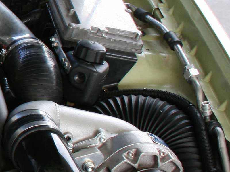
INTRODUCTION
Congratulations on selecting the best performing and best backed automotive supercharger
available today. Before beginning this installation please read this instruction booklet thoroughly.

CAPA Supercharger Systems are a performance improving device. This product is intended for use
on healthy and well maintained engines. Installation on a worn-out or damaged engine is not
recommended and may result in failure of the engine and or the supercharger. CAPA IS NOT
RESPONSIBLE FOR ANY DAMAGES RESULTING FROM THE USE OF THIS KIT.

For best performance and durability please take note of the following key points:

1.      Use minimum of 96-98 RON unleaded fuel
2.      The engine must have stock compression ratio.
3.      If the motor has been modified in any way, check with CAPA prior to installation.
4.      Change your oil and oil filter. Refill with the best synthetic oil available.
5.      Check that all components of the ignition system are in top condition.
6.      Cold Starts - never race your engine when your engine is cold. Allow water temperature to
        rise up to operating range before driving above 2500 r.p.m. Engine damage may result in
        high r.p.m. and boost conditions when cold.
7.      Always listen for signs of deterioration (pinging) and discontinue hard use (no boost) until
        the problem is resolved.
8.      Change oil and oil filter every 5,000km. OVER FILL OIL BY 1 LITRE WHEN KIT IS FITTED.
9.      Always use an air-filter.
10.     Never strike the supercharger pulley with a hammer or other tools. (Evidence of such force
        will void warranty).
11.     Retention belt after 500-600km, if not sooner, because the belt will stretch during initial
        brake in period. Tighten belt only enough to stop slippage (the belt must still have some
        flex), over tension of the belt is the cause of input bearing failure
12.     Never over-rev supercharger. Internal step up on a Vortech V-3 Supercharger is 1.0 to 3.60.
        Impeller speed must not exceed 50,000r.p.m (Sealed Vortech).

        Impeller speed calculated as below:

                               Vortech V-2 / V-3 Supercharger
           Crank Pulley Diameter     x 3.60 x Engine RPM = Impeller Speed
        Supercharger Pulley Diameter

        NOTE: The reason for grooved belts to move over one or more grooves or come off
        completely is always due to an alignment problem. Mis-alignment, can also be caused by
        over-tightening of the belt - which may damage the drive same.

BA8SC-MANUAL – V1.01                       Printed 25 May 2021                                -1-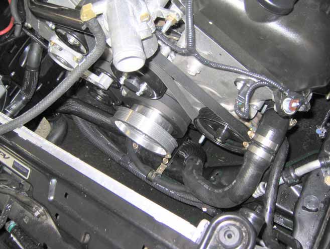
GLOSSARY
              COMPRESSOR HOUSING
              The housing, which makes up the enclosure portion of the compressor.
              Also referred to as the volute, scroll or snail.

              COMPRESSOR SURGE
              The phenomenon that occurs when the pressure ratio is too high for a
              given flow, or impeller speed. All centrifugal compressors can experience
              it. In automotive use it is most often found during decelerations when the
              engine speed is still high and the throttle is closed.

              DETONATION
              The uncontrolled rapid expansion or explosion of the air/fuel mixture in
              the combustion chamber.

              GAUGE PRESSURE
              The measure of pressure above atmospheric pressure.

              IMPELLER
              The bladed wheel inside the compressor housing that accelerates the air.

              INDUCER
              The air inlet portion of the compressor.

              NATURALLY ASPIRATED
              An engine without a supercharger.

              PRESSURE, BOOST
              The difference in pressure between barometric and intake manifold
              absolute pressure on a supercharged engine (read as gauge pressure).

              PRESSURE, ABSOLUTE
              The sum of gauge pressure and atmospheric pressure. One standard
                                                                      2
              atmosphere = 29.92 in. of mercury (Hg) = 14.696 lbs./in. (psi)

              PRESSURE RATIO
              Manifold absolute pressure divided by standard barometric pressure.
              P.R. = gauge pressure +
              atmospheric pressure
              absolute pressure

              STOICHIOMETRIC
              The correct chemical mixture of air and fuel to yield complete combustion.

BA8SC-MANUAL – V1.01                        Printed 25 May 2021                            -2-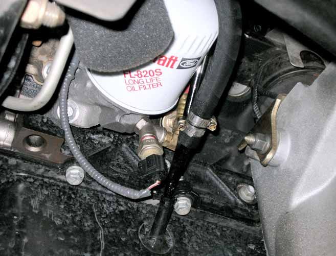
KITS PARTS LIST
Quantity Checked
OIL FEED & DRAIN SUPERCHARGER ASSEMBLY:
Vortech Supercharger unit Curved V2 (Non Intercooled Only) 1
Vortech Supercharger unit Curved Forward V2 (Intercooled Only) 1
500kW Only, T-Trim Option Curved Forward (Intercooled Only) 1
Oil Outlet, Straight Barb (Non-Intercooled Only) 1
Oil Outlet, 90 Degree Barb (Intercooled Only) 1
Modified Dipstick Tube BAT6754A 1
Vortech Oil Feed kit with 2 x 90 degree Fitting at Supercharger 1
Vortech Feed Line Conduit 13mm x 700mm 1
500mm x ½” Oil Drain hose 1
500mm x 20mm Conduit 1
8-22mm Hose clamps 2
Vortech Air Assist kit 1
SEALED SUPERCHARGER ASSEMBLY
Vortech V-2 Sealed, Special Outlet, Pre-Filled Special Lubricant, 180cc 1
Supercharger Surge Oil Bottle & Fittings 1
Oil Bottle Bracket plus 6mm self tapper bolt 1
250mm Blue Oil Feed Line 1
11-13 Clamps 2
PULLEY/BELT COMBO:
3.8 - 3.7 x 180mm = 1725 Belt __
3.6 - 3.47 x 180mm = 1715 Belt __
3.33 – 3.15 x 180mm = 1700 Belt __
2.95 x 180mm = 1675 Belt __
3.6 x 205mm = 1760 Belt __
3.33 x 205mm = 1755 Belt __
3.15 x 205mm = 1745 Belt __
Supercharger pulley 3/8 x 1-1/4NF bolt, spring washer & retainer 1
MOUNT / DRIVE SYSTEM:
3/8" x 1.5" UNC cap head bolts 5
Supercharger aluminium Mount Bracket 1
Mount bracket bolts 8M x 110mm, spring, flat washer 3
Mount bracket spacer 38mm x 25mm 1
Mount bracket spacer 45.5mm x 25mm 2
Double bearing idler pulley (flat) Alum, LS1+8mm Spacer 1
Idler pulley mount bolt M12 x 45mm 1
Idler pulley dished washer 12mm 1
Idler pulley spacer 6mm x 12mm 1
12mm Shimmed washers 6
Tensioner Pulley Double bearing (flat plastic) 1
Tensioner pulley mount bolt 2” x 7/16”NF 1
Tensioner pulley dished washer 7/16” 1
7/16” Shimmed Washers 6
Eccentric Tensioner 1-1/2” Total Height 1
Parts List continued on Next Page…
BA8SC-MANUAL – V1.01 Printed 25 May 2021 -3-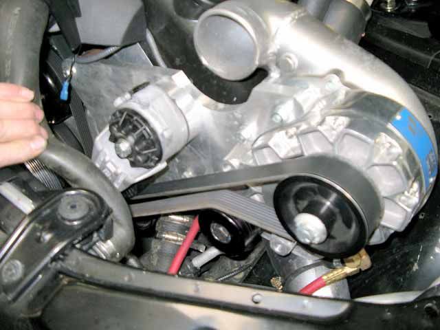
KITS PARTS LIST, CONTINUED
Quantity Checked
MOUNT / DRIVE SYSTEM (Continued):
Tensioner to bracket mount bolt ½” x 1-1/2” NF, spring washer 1
8 rib Aluminium Crank pulley 1
Small Tube Master gasket 1
Crank pulley retainer bolt M10 x 25mm, spring & flat washer 3
Bottom Radiator hose angle (Short 90 degree) 1
Radiator hose Joiner 69mm x 44mm 1
33-57mm Hose clamps 3
Bottom radiator Hose Support bracket 1
39mm Rubber lined D saddle 1
M6 x 20mm Bolt, spring, flat washer and nut 1
Power Steering Hose Conduit, 300mm x 25mm 1
Power Steering Hose Conduit, 300mm x 19mm 1
Large Cable Ties 2
AUTOMATIC TENSIONER DRIVE SYSTEM (OPTIONAL)
Automatic Tensioner Assembly w/Countersunk Housing 1
22mm Chamfered 2 Piece Spacer Assembly 1
100mm x 10mm Allen Head Bolt 1
25mm x 8mm Countersunk Bolt 1
50 x 10mm Bolt (Idler Pulley to Tensioner Assembly) 1
10mm Spring Flat Washer and Bearing Spacer 1
17mm Shim 3
AIR DISCHARGE: (SUPERCHARGER OUTLET)
Supercharger to Aluminium air duct 55mm x 76mm Silicon Tube 1
Aluminium Tube with Grommet 1
65 -89mm hose clamps 4
Modified 90 degree Rubber angle (One end less 25mm) 1
By-Pass Valve 1
1000mm 1” By-Pass Valve tube 1
1000mm 4mm Vacuum Hose 1
By-Pass valve sock and tie 1
Plastic Ties Large 6
AIR INLET: (STARTING AT SUPERCHARGER)
Convoluted Intake Tube, 3.5” x 1000mm 1
500kW option only, Convoluted Intake Tube, 4” x 1000mm 1
89 - 104mm hose clamps 3
500kW option only, 104-106mm hose clamps 3
PCV Breather fitting 12.5mm (to inlet tube) 1
One Way Valve, PCV Type Low Pressure 1
8-22mm Hose clamp 1
400mm Breather hose (flared one end) 1
3.5” Air Filter mount Rubber angle 45 x 3” with sleeve inserts 1
K&N Filter Element 1
500kw option only, 4” K&N Filter 1
500kw option only, 4” Filter to Convoluted Hose Joiner Sleeve 1
Air Filter low Warning sticker 1
M6 Counter-sunk Allen head bolt 1
Parts List continued on Next Page…
BA8SC-MANUAL – V1.01 Printed 25 May 2021 -4-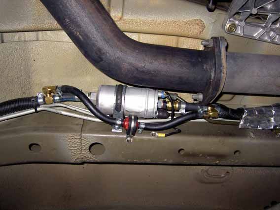
KITS PARTS LIST, CONTINUED
                                                                             Quantity   Checked
FUEL MANAGEMENT - NORMAL:
      Optional – 30lb Injector Upgrade for XR8 (Non Flash Tuner Only)           8
      Note: GT / GTP 30lb Injector Upgrade Mandatory
      Fuel Management Unit (10:1)                                               1
      Curved FMU Fittings                                                       2
      1200mm x 8mm EFI Hose (FMU)                                               2
      1200mm x 16mm Conduit                                                     2
      12 - 14mm fuel hose clamps         (FMU)                                  6
      Self Tapping/Drilling Screws                                              2
      1000mm x 4mm vacuum hose                                                  1
      4mm Brass T Piece                                                         2
      Premium Unleaded & Synthetic Oil Only Stickers                            1
      T-Rex Fuel Pump                                                           1
      Fuel Pump mount bracket                                                   1
      Fuel pump D mount saddle                                                  1
      Pump Insulation Wrap                                                      1
      One-Way Valve                                                             1
      5/16” Barbed T-Piece                                                      2
      50mm x 5/16” EFI hose and protective Conduit                              2
      150mm x 5/16” EFI hose and protective Conduit                             2
      70mm x 5/16” EFI hose and protective Conduit                              1
      600mm x 8mm EFI hose and protective Conduit                               1
      Fuel Hose Clamps 10-12mm                                                  12
      M5 x 15mm Bolts, nut spring and flat washer                               2
      Plastic Ties (medium)                                                     10
FUEL MANAGEMENT – BOSCH UPGRADE:
      Bosch 044 Fuel Pump w/-8 Inlet and Discharge Fitted                       1
      One-Way Valve                                                             1
      One-Way Valve Saddle and Screw                                            1
      3/8 Barb Tee, 5/16 90 Degree Outlet                                       2
      200mm x 5/16” EFI hose and protective Conduit                             2
      1400mm x 10mm EFI hose and protective Conduit                             1
      Fuel Hose Clamps 14-16mm                                                  10
      Fuel Hose Clamps 12-14mm                                                  4
      Plastic Ties (medium)                                                     10
      Silver Insulation Sheet                                                   2
      3/8 High Flow Fuel Filter                                                 1
      1200mm x 3/8 Steel Tube                                                   1
      3/8 Steel Tube Saddle                                                     4
      Self Tapping Screws                                                       6
      Plastic Ties (medium)                                                     10
FUEL MANAGEMENT – INJECTOR / REGULATOR COMBINATION
      8psi - 10:1 Reg, T-Rex Fuel Pump, Standard Injectors – XR8 (All)          __
      8psi - 10:1 Reg, T-Rex Fuel Pump, 30lb Inj. – GT, GTP (Non Interocoled)   __
      8psi - 10:1 Reg, Bosch Fuel Pump, 30lb Inj. – GT, GTP (Intercooled)       __
      9psi - 8:1 Reg, 36lb Injectors – Special Application                      __

Parts List continued on Next Page…

BA8SC-MANUAL – V1.01                           Printed 25 May 2021                                -5-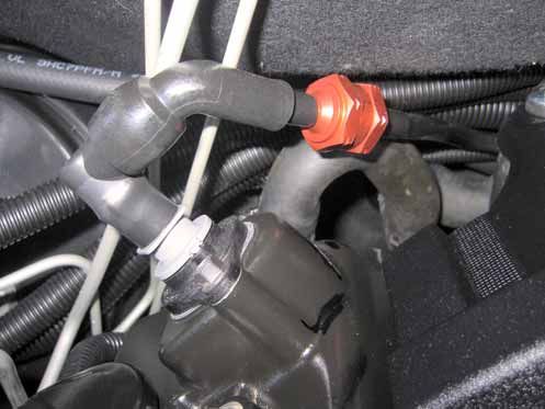
KITS PARTS LIST, CONTINUED
                                                                       Quantity   Checked
ELECTRICAL SYSTEM:
      Fusible link double wire                                             1
      M5 x 15mm bolt, nut, spring and flat washer                          1
      Relay, Base & mount screw         (refer water injection kit)        -
      2000mm of 10mm ID Conduit                                            1
      2000mm 2 core wire (fuel switch)                                     1
      2000mm of 6mm ID Conduit                                             1
      2500mm red 5mm wire (fuel pump)                                      1
       Female terminals                                                    2
      8mm eye terminals                                                    1
      5mm eye terminals                                                    2
      6.3mm eye terminals                                                  2
      Piggy back controller                                                1
      Scotch Locks                                                         2
      Blue hole Terminal & Self Taper (earth)                              1
      Fuel Pressure switch in T piece (refer to water injection kit)       -

Important before beginning installation, verify that all parts are included in the
kit - report any shortages or damaged parts immediately.

BA8SC-MANUAL – V1.01                             Printed 25 May 2021                        -6-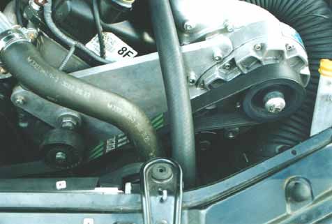
PREPARATION & PART REMOVAL
1. Disconnect Battery.
2. Remove Engine Cover.
3. Remove air cleaner box & ducting.
4. Remove Air Box Mount bracket assy. (Drill rivets)
5. Remove Spark Plugs
6. Remover Power-steering fluid reservoir (Drain and keep fluid)
7. Drain Coolant system. (keep fluid)
8. Remove cooling fan assembly.
9. Remove Radiator hose support bracket.
10. Remove Bottom radiator hose. (engine clamp side)
11. Remove Front Grille.
12. Remove front Bumper assembly.
13. Remove Passenger side headlight.
14. Remove oil light switch
15. Remove dipstick tube (NOTE: Ensure that your dipstick is part no: 8912 6750-AC, if your
dipstick is different, please contact CAPA).
SPECIAL TOOLS
dyno or use of
accurate air fuel ratio meter
boost gauge
fuel pressure gauge
fuel return gauge
long straight edge
FUEL SYSTEM ENHANCEMENT
NOTE: If kit is modified in the future with the understanding that it violates supercharger
warranty, these are the recommended fuel system changes.
Option 1: 4-5psi Tune with Flash Tuner. Optional 2 bar map / tune.
Option 2: 6psi 36# Injectors, Tune with Flash Tuner. Optional 2 bar map / tune.
Option 3: 7psi 42# Injectors, Tune with Flash Tuner. Optional 2 bar map / tune.
Option 4: 8psi 42# Injectors, Mini T-Rex Fuel Pump with Flash Tuner. Optional 2 bar map / tune.
Option 5: 9psi 42# Injectors, T-Rex Fuel Pump, Vortech FMU, Flash Tuner. Optional 2 bar map / tune.
Option 6: 10psi 42# Injectors, Bosch 044 Fuel Pump, Vortech FMU, Flash Tuner. Optional 2 bar map / tune.
Option 7: 10psi+ 42# / 60# Injectors, Bosch 044 Fuel Pump, Vortech FMU.
Optional 2 bar map / tune. Fuel Cell & Bosch 413 Fuel Pump.
BA8SC-MANUAL – V1.01 Printed 25 May 2021 -7-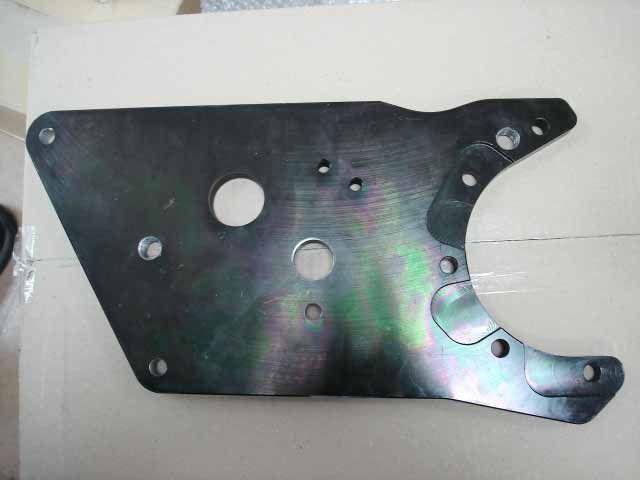
INSTALLATION
1.      Check Spark Plugs, replace with NGK BPR6EF, gapped to 1mm if required.

2.      With bottom radiator hose out of the way, fit new crankshaft pulley assembly. Tension to
        44lbs. Using three M10 x 25mm bolts provided, smear Master gasket supplied on threads
        and tension accordingly.

                                                 PHOTO 1

3.      With radiator hose removed fit right angle hose and join with joiner supplied to original
        hose, route the hose down and under the crankshaft pulley, using clamp and bracket
        provided, fit straight bracket to hold the hose behind the crossmember. Remove original
        hose support bracket. Secure hose to bracket with saddle supplied. Ensure supercharger
        belt or crankshaft pulley have ample clearance. (See Photo2)

                                                 PHOTO 2.
BA8SC-MANUAL – V1.01                      Printed 25 May 2021                              -8-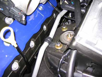
4. OIL FEED AND DRAIN KITS ONLY - With oil light switch removed, fit ‘Y’ adaptor at oil light
switch, route hose towards, where supercharger will be situated. *Fit Dipstick tube provided
(NOTE: Ensure that your dipstick is part no: 8912 6750-AC, if your dipstick is different,
please contact CAPA), use clamps to secure hose (See Photo 3) If Automatic Transmission,
Route Supercharger Drain Hose In Front of transmission cooler pipes. *Fit Drain Hose to
Supercharger first before fitting supercharger into bracket.
Air Assist Installation
PHOTO 3.
5 *Supercharger should have inlet pipe also fitted to supercharger when installing to bracket.
*Relocate ABS wire to front of left hand inner guard and down along chassis rail. *Relocate
main wiring loom, now clips behind and through headlight hole to new position through
headlight hole alongside air-conditioning pipe above chassis rail. OIL FEED AND DRAIN
KITS ONLY Ensure air assist is fitted to supercharger, use drawing to ensure correct
installation.
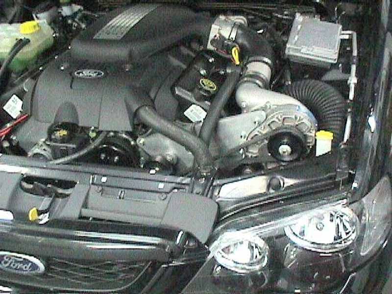
BA8SC-MANUAL – V1.01 Printed 25 May 2021 -9-6. SEALED SUPERCHARGER KITS ONLY: With supercharger in position connect supercharger
oil reservoir in position as shown in photo using self tapping screws supplied.
7. Modify water injection / washer bottle as per “Water Injection Manual”. (See Photo 4)
NOTE: You may wish to complete water injection fitment now or continue the main
installation and finish water kit later.
PHOTO 4.
PHOTO 4a PHOTO 4b
OPTIONAL: You may wish to fit an auxiliary water washer bottle and remove original washer
bottle. Then air filter tube will go through hole indicated by circle on photo 4b. You may
have to enlarge the hole to make this possible. This will be less restrictive than running inlet
under headlight.
BA8SC-MANUAL – V1.01 Printed 25 May 2021 - 10 -8. Fit Air filter tube in position along inner wheel arch, down through headlight hole. Replace
support bolt on bracket mounting air con line near the inspection/fill port on air-con line,
with 6mm counter sunk bolt provided (thus stopping bolt from protruding into intake tube).
You will have to bend air conditioner Aluminium tube up above air filter tube and slightly
compress tube to fit between supercharger and inner guard (See Photo 4a). Fit PCV
breather fitting in into filter hose, then secure PCV hose with clamp provided. (See Photo 5).
After fitting to supercharger trim to correct length, fit rubber angle and K&N Filter pod. (See
Photo 6 )
NOTE: Fit inlet tube to supercharger when supercharger / bracket is in position, but not
secured.
PHOTO5 PHOTO6
9. With cam sensor plug from cylinder head removed, make a decision wether you wish to
extend wires or remove insulation tape to lengthen plug loom to suit. Ensure plug and loom
go through hole in bracket before the bracket is mounted.
NOTE: Space Bracket to ensure bracket does not rub against tappet cover. This will cause a
vibration noise through the car.
Shown below is photo of bracket, description of all mounting points.
A Engine mounting point – Use spacer 45.5mm
B Engine mounting point – Use spacer 45.5mm
C Engine mounting point – Use spacer 38mm
D Automatic Belt Tensioner Mount Points
E Gilmer Drive Only – Idler Mounts (Steel Bracket Only)
D D
A E
E
C
B
BA8SC-MANUAL – V1.01 Printed 25 May 2021 - 11 -10. Remove the three bolts on the front cover of the engine, that co-inside with the bracket
fitment and secure with M8 x 110mm bolts provided. Two different length spacers are
provided, 45mm & 38mm (See diagram above).
Put Supercharger unit into position (inlet tube connected) slot bracket into supercharger
put two bolts in supercharger unit, 1¼ x 3/8NC cap bolts (leaving loose). With spacers and
bolts mentioned above, secure bracket to front of engine (nip bolts up don’t tension). Fit
remainder of supercharger to bracket bolts and nip up.
NOTE: Position scroll on supercharger, by loosening tabs and rotating housing, this may
already be done for you. (See Photo 5) Ensure this is done before supercharger is put in
place.
11. Check blower pulley is running true with crank - shaft pulley. With a long straight edge,
check that the blower lines up with the crankshaft pulley. Check that the blower is on the
same vertical tilt angle as the crankshaft pulley, you can use a fishing line with a weight on
the end of it to check this. Position the car so that the vertical tilt line is square with the
crankshaft pulley. Check this against the blower pulley to make sure that the blower and
bracket are at the same vertical tilt angle. Check against other pulleys if possible just for
your own reference that you are measuring vertical. Check the measurement from straight
edge to the first pulley groove on the crankshaft pulley, it must be the same on the blower
pulley. Take this into consideration when adjusting the idler pulleys as well. Re check
alignment after tightening all bolts.
NOTE: If unsure call for assistance, this is important. If you don't get this right, the belt will
move on the idler pulley when you rev up the motor underload above 3500rpm.
BA8SC-MANUAL – V1.01 Printed 25 May 2021 - 12 -12. Fit Flat idler pulley to supercharger middle of three threaded post, fit eccentric tensioner
assembly to bracket, ensure both idler and tensioner are in alignment. Fit the blower belt
provided. Tension belt idler pulley only. Tension belt tightly enough to eliminate slippage.
Re-tension the belt after 500km. Do not over tighten the belt. (See Photo 7)
Automatic Tensioner Option
With Automatic Tensioner option the manual tensioner is not used, the new position for the
tensioner is shown in a photo below. The 22mm Spacer Provided will need some machining
to chamfer, this counteracts for any deflection of the tensioner to ensure the idler pulley
tracks perfectly. In some cases you may wish to shim under spacer, a spacing is generally
needed in the area shown in the photo by an arrow.
NOTE: Check belt for clearance to cooler hoses under belt.
PHOTO 7a
PHOTO 7
13. To recheck that all pulleys lines up. Later, wind the motor over, then start the motor. Let
idle and check. Then rev up motor to check if the belts walk off the pulleys. Do this task at
the end of the fitment tasks. Continue checking the belt during breaking in procedure
and complete the rev up test at the end of the breaking in procedure. Before road test
review the final checklist.
14. Refit Engine cooling fans, re-route power steering hoses, cutting both ends off hoses and
secure to cooling fans. Fit conduit over hoses before securing (See Photos 1&2) Refit Power
steering reservoir and refill.
BA8SC-MANUAL – V1.01 Printed 25 May 2021 - 13 -15. Fit Discharge pipe with rubber joiner and angle supplied. Use clamps supplied to secure.
Ensure 90 degree rubber angle at throttle body is fitted to throttle body with short end to
throttle body. Rubber hose should not contact computer bracket. Cut Strut Stud Tip to
ensure it doesn’t rub through throttle body tube.
(See Photo 5 and 7a)
16. Connect the blow-off valve to the Aluminium tube. Connect Blow-off valve to 25mm
Blow-off tube supplied. Route Blow-off valve hose over bracket and down towards
chassis rail fitting foam sock on end with plastic tie. Ensure hose has plenty of clearance,
so it will not run on top of supercharger drive belt. (Use plastic ties to secure tube where
required.)
The sock reduces blow-off valve noise on deceleration/idle, when valve is open.
17. Source vacuum/boost reference from line going to std fuel regulator, using T-piece and
4mm hose supplied for Blow of valve. Route around front of engine, towards brake
master cylinder, this will provide reference for FMU and water injection switch. Clamp all
ends with fittings supplied.
18. Connect new crank-case breather hose from intake tube to original breather hose. Use
connector at intake hose and original joiner on original hose (See Photo 5)
Using one way valve provided, fit to pcv valve on driver’s side, cut plastic hose and push
one way valve into plastic hose, will lock in. This will stop boost pressurising sump.
Danger: Do not mix this one way valve with fuel pump one way valve. They look the
same, but have different internal valve.
Direction of Flow
19. With air filter in correct position, as per (Photo 4&5) and water injection installation
complete, refit headlight, bumper bar and grille.
PRECAUTION: The air filter is mounted in this position to ensure that it collects the
cold air without being effected from engine bay temperature. You will notice that
its position is lower on the car than original mounting position. Take this into
consideration when attempting water crossings in extreme conditions the
possibility exists of WATER ENTERING THE INTAKE. ENSURE ALL DRIVERS ARE
AWARE OF THIS POSSIBILITY AND TAKE NECESSARY PRECAUTIONS
BA8SC-MANUAL – V1.01 Printed 25 May 2021 - 14 -20. Mount CAPA pump beside inlet manifold, behind throttle body, with bracket provided, as
indicated in ( Photo8 & 9). Mounting to tappet cover bolt under idle motor. Ensure rubber
insulation wrap is fitted to pump prior to clamping and no part of pump will chafe. See
Drawing Below for pump/hose layout.
PHOTO 8 PHOTO 9
NOTE: The secondary pump increases flow and pressure as the original system becomes
inadequate, the secondary pump needs to be switched on at around 2.0psi, this also
activates the water injection off the one switch. When clamping fuel hose, spray hose with
CRC to ensure clamps do up with out pinching fuel hose.
BA8SC-MANUAL – V1.01 Printed 25 May 2021 - 15 -Bosch Pump Upgrade
For GT or High Output, an optional 044 Bosch fuel pump is supplied. This pump is fitted in a
different position to the T-Rex pump. The fuel filter clamp now clamps the fuel pump to the chassis
and the fuel filter is now located near the fuel rail. Part of this process requires removing the fuel
pump assembly from the tank, breaking out the one way valve located at the bottom of the fuel
pump bowl, and opening the orifice by 1.5mm. Ensure no plastic swarf is left behind. Refit the
pump assembly replace original 5/16 tube from fuel tank to fuel pump with flexible 3/8 hose
provided. Replace 5/16 steel tube from pump to engine with 3/8 steel tube provided. Fit fuel filter
and connect to fuel rail. Assemble pump and one way valve as shown in photo. One way valve
must flow forwards from tank to engine. Ensure wiring earth is screwed securely so not to come
loose and seal with silicon to keep connection dry and free of corrosion. Cover fuel pump and
tubing from pump to engine with silver insulation provided, this is a must to ensure reliability. In
most cases when this option is utilized injectors are usually replaced. Ensure injector o-rings are
lubricated when fitted into fuel rail. New injectors will not have a positioning slot, position injectors
in rail in conventional fashion, they will not move once rail is clamped down. Ensure all electrical
connectors are clicked in properly.
Fuel Flow
BA8SC-MANUAL – V1.01 Printed 25 May 2021 - 16 -21. Mount relay near fuse box and wire using the 6mm red wire provided, run the wire from the
pump to the relay fuel pump as per above diagram.
Test fuel pump system to ensure it maintains adequate flow and pressure at top boost,
do this test with hot fuel and headlights on high beam.
NOTE: Fuel systems runs under high pressure, check all clamps and tighten, check hoses
are in good condition or replace. This fuel system has no fuel return line.
22. Fit FMU near brake booster, as per (Photo 10.) Route hoses under booster, around back of
engine, and connect to return system, as per diagram next page. Cut plastic section out
between firewall and engine, and discard. Double clamp and conduit hoses. Ensure hoses
are not too long and are secured to prevent any vibration noise on firewall etc. Connect
vacuum tube to same source as discussed previously for Blow-off valve and pressure switch.
PHOTO 10
BA8SC-MANUAL – V1.01 Printed 25 May 2021 - 17 -9
2 3 10
1
4
8
5
6 7
IT E M D E S C R IP T IO N
1 F U E L P R E S S U R E C O N TR O L L E R F M U
2 C O N N E C T T O M A N IF O L D V A C U U M /P R E S S U R E A T V A C U U M T R E E
3 IN L E T F U E L L IN E IN T O F M U S ID E F IT T IN G F R O M F A C T O R Y R E G U L A R O R
4 F U E L R E T U R N L IN E T O F U E L T A N K
5 F U E L F E E D L IN E
6 F U E L TA N K
7 FUEL PUM P
8 E N G IN E
9 V A C UUM SO UR C E
10 F U E L R A IL
23. Drain fuel tank and refill with Premium or Optimax fuel.
24. Refill engine coolant system. Also changing engine oil and filter with a good quality engine
Oil. Start engine, let idle for 10 minutes, purge cooling system and seal. Checking for any
water/oil/vacuum/power steering leaks
25. A Flash Tuner is required with this kit, available for purchase separately. Contact CAPA for
more details.
26. While engine is running check that belts are running true (Re - check steps 11-13) and re
ensure that all fittings are secured correctly and no leaks are present.
27. Review ‘Breaking In’ procedure.
BA8SC-MANUAL – V1.01 Printed 25 May 2021 - 18 -WATER INJECTION
Water injection is available and has its benefits.
1. Maintaining a cooler intake charge due to the evaporation of water.
2. Reducing heat soak at blower and inlet manifold.
3. Added protection for detonation on extremely hot days.
BREAKING IN
Run motor at idle and fast idle for 5 to 10 minutes, do not rev up motor, then stop motor allow
blower to cool for 10 minutes, then drive at no boost for approximately 10 minutes, not exceeding
3,000rpm, then allow blower to cool. Drive vehicle not exceeding 3,500rpm at no boost for
approximately 100 to 150kms. This will ensure that the bearings and drive belt are run in before
loading up the system by boosting. Always warm the motor - blower, before using boost. This will
help in the life longevity of both the motor and blower. Before driving, review the Final Check
List. This procedure is very important and must be carried out to the letter. Dyno tuning may
only be done after this procedure is completed.
Do not dyno run car until the 100-150km has been driven.
GENERAL NOTES
It is the installers responsibility to dyno the car to check that all systems are working correctly,
especially maximum fuel delivery and to check for any presence of detonation.
Check boost on dyno and that advertised boost is not exceeded and rpm occurs at designated rpm.
Have injectors cleaned and flowed. A must on used injectors, peace of mind on new injectors.
Make sure that all fuel hoses are in excellent condition, or replace. Check that all clamps are tight
and that there are no fuel leaks.
The blower will have a sweet high-pitched whirring noise from the belt drive. As the blower goes
through its running in time, the noise will slowly dissipate.
ENSURE ENGINE OIL IS OVER-FILLED BY 1 LITRE MORE THAN OE SPECS..
PRECAUTION: If the blower ever gets louder or starts to make an erratic noise or a noise through
the intake tube, such as a air hissing noise, disconnect the blower belt and call CAPA for assistance
and advice.
BA8SC-MANUAL – V1.01 Printed 25 May 2021 - 19 -FINAL CHECKLIST
1. Carefully review the entire installation. Check oil and fuel lines near moving parts and the
exhaust system to ensure that these lines are safe, secure and not twisted or kinked. All
wires and hoses should be firmly secured with clamps or wire ties.
2. Check all fluid levels. Your vehicle should be filled with premium fuel before any driving. It
is important that you performed an oil and filter change. If you did not do so before, it
should be performed now before proceeding further.
3. Start engine and idle for a few minutes. Check your timing. You want to run as much timing
as possible while avoiding detonation. It is better to lean on the side of less timing and no
detonation!
4. Shut off your engine and check for fluid leakage, signs of rubbing parts, and other potential
problems. Pay particular attention to fuel leaks, check by using CRC spray any vacuum leaks
at base of injector.
5. Check nothing is near any hot spots.
6. Your vehicle should display a significant increase in performance when you step into the
throttle, with no detonation, yet should maintain its previous driveability during daily
driving. If this is not so, review your installation, then contact CAPA assistance.
7. For best performance and reliability, always use premium or higher-grade fuel and listen
for signs of detonation. Back off throttle should detonation occur. With a properly installed
supercharger and appropriate timing, detonation should not be an issue.
8. Never race your engine when your engine is cold. Allow the water temperature to climb
into operating range for several minutes before driving above 2,500r.p.m. to ensure
adequate oil lubrication.
9. Please review the maintenance and warranty sections within this owner's manual.
10. Please take special note; operation of vehicle without all sub assemblies completed and
properly installed may cause failure of major components.
11. After road test or first hard drive, check belts are okay and running properly in their grooves.
Check the tension of belt and retension if necessary.
12. Re dyno after 2,000km's.
BA8SC-MANUAL – V1.01 Printed 25 May 2021 - 20 -WARNING
1. DO NOT ATTEMPT TO OPERATE VEHICLE UNTIL ALL COMPONENTS ARE
INSTALLED AND COMPLETE. SUPERCHARGER KITS EXTRUDE A HUGE AMOUNT
OF HORSEPOWER FROM A STOCK ENGINE THEY ARE NOT INTENDED FOR
CONTINUOUS OR EXTREME PERIODS OF MAXIMUM POWER OUTPUT. IT IS NOT
OUR INTENTION TO CREATE RACE PROVEN HORSEPOWER BUT LEISURE
ENDURING SYSTEMS.
2. WARRANTY POLICY FOR 12 MONTHS, UNLIMITED KILOMETRES COVERS FAULTY
COMPONENTS PROVIDED IN SUPERCHARGER KIT. POLICY DOES NOT INCLUDE
LABOUR TO REPLACE FAULTY PARTS.
3. THE RESPONSIBILITY OF ADR COMPLIANCE AND INSURANCE FOR THIS KIT
FITTED TO A VEHICLE THAT IS ROAD REGISTERED AND DRIVEN IS THE
RESPONSIBILITY OF THE VEHICLE OWNER.
4. RESPONSIBILITY FOR CORRECT FITMENT OF THE KIT IS THE REPONSABILITY OF
THE FITTER.
5. DAMAGES TO VEHICLE OR SURROUNDS IS THE RESPONSIBILITY OF THE VEHICLE
OWNER. PROVIDED THE KIT FITMENT IS CORRECT, ACCORDING TO THIS
MANUAL.
GET OUT THERE & ENJOY...
BA8SC-MANUAL – V1.01 Printed 25 May 2021 - 21 -You can also read