Smart Ultrasonic Welding in Power Electronics Packaging - Hesse GmbH
←
→
Page content transcription
If your browser does not render page correctly, please read the page content below
Smart Ultrasonic Welding in Power Electronics Packaging
Matthias Hunstig, Waldemar Schaermann, Michael Brökelmann, Sebastian Holtkämper, Dirk Siepe, Hans J. Hesse,
Hesse GmbH, Paderborn, Germany

Abstract
Ultrasonic metal spot welding is a standard technology used in power electronics packaging, mostly for welding power
terminal connectors to direct bonded copper (DBC) substrates. Ultrasonic wire bonding is a very similar technology, yet
there are significant differences regarding processes, applications, and available equipment. Production equipment com-
bining the ultrasound power of welders with the flexibility, precision, and process control of wire bonders into a “smart
welding process” is highly desired. This contribution compares the technologies and presents process results for a cylin-
drical cell battery pack. They highlight the advantages of smart over classic ultrasonic welding and demonstrate that smart
ultrasonic welding and wire bonding have individual strengths and weaknesses.

1      Ultrasonic welding and wire                                from the fact that there is no vibration amplitude in the cen-
                                                                  ter of the contact, and thus often insufficient joining.
       bonding in power electronics                               Ultrasound transducer and sonotrode usually only have a
The two technologies of ultrasonic metal spot welding and         vertical degree of freedom, so the products to be welded
ultrasonic wire bonding are both commonly used in power           must be placed underneath the welding tip with the correct
electronics packaging. There are many principal similari-         orientation. The welding tool tip must be large enough to
ties between the two, but also a number of practical differ-      cover manufacturing and placement tolerances and suffi-
ences regarding processes, equipment, and applications.           cient space must be provided in product design. The normal
                                                                  force is commonly applied pneumatically, sometimes hy-
1.1    Ultrasonic metal spot welding                              draulically or electromagnetically. Some machines with
                                                                  off-axis force application apply a torque to the sonotrode
In ultrasonic metal spot welding, two (or more) metallic
                                                                  instead of a force in order to generate the required contact
partners are joined in a discrete area. It is the most relevant
                                                                  force. Figure 2 shows a typical machine used for ultrasonic
ultrasonic welding technology in power electronics appli-
                                                                  metal spot welding, which uses torsional sonotrode vibra-
cations, other ultrasonic welding technologies join plastic
                                                                  tion to create a quasi-transverse vibration at the welding
parts and/or form continuous joints.
                                                                  spot (type E in Figure 1).
Machines for ultrasonic metal spot welding create mechan-
                                                                  Typical ultrasonic metal spot welding machines provide ul-
ical vibrations with amplitudes of several µm in the low
                                                                  trasound powers of 0.5 to 10 kW at frequencies between 15
ultrasonic frequency range (typically 15 to 40 kHz), which
                                                                  and 40 kHz, with the corresponding normal force reaching
are transmitted to the welding spot through a so called
                                                                  up to 10 kN. Contact areas of up to 100 mm² can be welded
sonotrode. The contact partners are pressed between the vi-
                                                                  at sheet thicknesses of up to 5 mm.
brating sonotrode tip and a stationary (or passively vibrat-
ing [1, p. 263f]) support, often called anvil. Through the
application of vibration energy under pressure, the two
                                                                  1.2    Ultrasonic heavy wire bonding
parts, which can be of dissimilar metals, are joined in a         Ultrasonic wire bonding is a standard technology used to
solid-state process, i.e. without melting [1].                    produce electrical interconnections in micro and power
The design of ultrasonic metal spot welding machines var-         electronics [4]. An automatic ultrasonic wire bonder sup-
ies and so do the incorporated piezoelectric transducers          plies a wire with round or rectangular cross-section (rib-
which create the vibration. Commercially available ma-            bon) from a spool and the wire is welded (“bonded”) to a
chines can be classified into the five groups shown in Fig-       defined first position. The machine then forms a wire loop
ure 1, with the classic and most common types being the           by moving the bond head following a defined trajectory,
“lateral drive” (A) and the “wedge-reed” (B) designs [1; 2,       bonds the wire to a second position and finally severs the
p. 138ff]. The machine designs have individual advantages         wire. Figure 3 shows a snapshot of a heavy wire bonding
and disadvantages. For example, machines with transverse          process between first and second bond.
contact vibration (types A, B, D, E) can suffer from “ham-        Automatic wire bonding machines can precisely move and
mering”, undesired vertical vibration which can impair            rotate the ultrasound transducer with the bonding tool. The
process stability and damage the substrate. This can usually      machine can thus produce multiple connections at different
be compensated by modification of the mechanical setup            locations, orientations and heights within one or multiple
and parameterization of the process. On the other hand,           products, without the products being moved. This allows
machines with torsional contact vibration principally suffer      tight spacing and thus compact products. Linear motor

                Submitted for publication in the proceedings of CIPS 2020 – 11th International Conference
                    on Integrated Power Electronics Systems, Berlin, Germany, March 24–26, 2020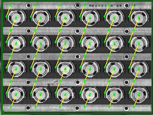
driven kinematics enable precise and fast movements, re-                               (type D in Figure 1), the physical joining process is iden-
sulting in high speed processes with multiple wire bonds                               tical. For this reason, ultrasonic wire bonding is sometimes
per seconds. The normal force is applied by a precise elec-                            called “ultrasonic micro welding” [5]. In microelectronic
tromagnetic actuator, allowing the normal force to be con-                             applications, wire bonding uses about 1 W of ultrasound
trolled and changed dynamically during the bonding pro-                                power at frequencies between 60 and 150 kHz. Typical
cess.                                                                                  wire bonding machines for power applications work with
                                                                                       maximum nominal powers of 100 W at frequencies be-
                                                             normal                    tween 40 and 100 kHz. Depending on material, these ma-
                                                             force
                                                                                       chines can process round wire diameters of up to 600 µm
                                                                                       and ribbon cross-sections up to 400 x 2000 µm². Typical
                                                                                       materials are Al, Cu, and Al-clad Cu.

                                                                      sonotrode
                                  normal
                                  force

                          sonotrode
 vibration                                  vibration
              anvil                                      anvil
         (side view)                                (side view)

(A) transverse contact vibration           (B) transverse contact vibration
from directly applied longitudi-           from longitudinal sonotrode vi-
nal sonotrode vibration; normal            bration, transmitted through bend-
force (or torque) applied off-axis         ing beam; normal force applied
(“lateral drive design”).                  axially (“wedge-reed design”)
                  normal
                  force

 sonotrode                                                                    normal
                                                                              force
                                                                                       Figure 2 Ultrasonic metal spot welding using a Telsonic
                                                                                       MPX machine, working at 20 kHz with a maximum power
                                                                      sonotrode        of 6.5 kW (image from [3], used under license CC BY 4.0,
 vibration                                                                             cropped and label removed)
              anvil
   (front view = side view)

                                            vibration
                                                         anvil
                                                    (side view)

         (top view)

(C) torsional contact vibration (D) transverse contact vibration
from torsional sonotrode vibra- from longitudinal sonotrode vi-
tion; normal force applied axially bration, transmitted through bend-
                                   ing beam; normal force applied
                                   off-axis
                                                          normal
                                                          force

                                                                                       Figure 3 Heavy copper wire bonding on test substrate
             sonotrode                       sonotrode
                                                                                       An automatic ultrasonic wire bonding machine could thus
 vibration
                                                                                       be described as a conventional ultrasonic spot welding ma-
                                                                                       chine with low power and extended functionality. This in-
               anvil             anvil
                                                                                       cludes fast and precise movement of the transducer in four
         (front view)                      (side view)
                                                                                       axes, freely programmable courses of ultrasound vibration
(E) transverse contact vibration from torsional sonotrode vibration;                   amplitude and normal force, and supplying, forming, and
normal force applied off-axis                                                          severing the wire. Current automatic wire bonding ma-
Figure 1 Types of ultrasonic metal spot welding machines                               chines also include advanced functions not common to
                                                                                       metal spot welding equipment. Some of these functions,
The bonding process itself is principally a very low power                             such as pattern recognition, touchdown sensing, and nor-
ultrasonic metal spot welding process using a machine with                             mal force control, are mandatory to produce reliable con-
transverse vibration transmitted through a bending beam                                nections between the small wires and the often sensitive
                                                                                       substrates. Other features, such as diverse advanced

                         Submitted for publication in the proceedings of CIPS 2020 – 11th International Conference
                             on Integrated Power Electronics Systems, Berlin, Germany, March 24–26, 2020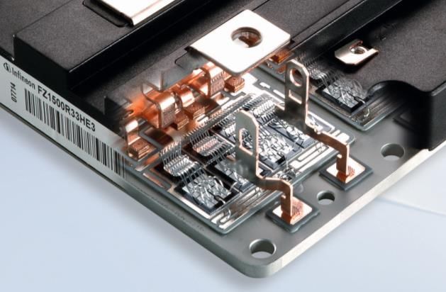
process control functions, standardized interfaces for as- observed quantities are outside certain limits, a joint is re-
sembly line integration, and the flexibility to handle a large garded as suspicious. Such tests do not consume any time
variety of products and layouts with one series machine by and can thus be applied to 100 % of the joints. As tests have
a mere change of clamping and programming, provide the shown that not all bad wire bonds could be identified using
user with increased control and flexibility. current and deformation alone [9, 10], frequency observa-
tion is very common in wire bonding nowadays. Still, this
1.3 Applications in power electronics pack- does not guarantee identification of all potentially bad
aging welds. Thus, more advanced quality control systems use
additional independent quantities to determine joint qual-
Typical power electronics packaging applications for ultra-
ity.
sonic metal spot welding are terminals and power contacts,
One such system, productively used in wire bonders for
e.g. in IGBT or inverter modules, as well as busbar con-
several years, is the multidimensional Process integrated
nections. Such ultrasonic welding is only used on robust
Quality Control (PiQC) [9, 10]. Using an additional sensor
passive material such as DBC and terminals, while heavy
integrated into the ultrasound transducer, it evaluates five
wire bonding is also commonly used to produce connec-
different physical quantities over the whole length of the
tions on sensitive active substrates such as chips, even with
process: mechanical vibration of the welding tool, friction
hard wire material such as copper [6, 7]. In fact, many
in the welding zone, wire deformation, transducer imped-
power modules use wire bonding for internal connections,
ance, and operation frequency, i.e. transducer resonance
e.g. die to die, die to DBC, and higher power ultrasonic
frequency. From their course over the process time, it cal-
welding for connecting the external power contacts. Fig-
culates quality indices for each of these quantities based on
ure 4 shows an example of such a combination. Wire bond-
a previously learned set of reference welds representing a
ing is also increasingly used in the production of Li-ion
good, stable process. This process automatically excludes
battery packs [8].
outliers. The quality indices are calculated based on the de-
viation of each signal from the reference course, weighted
by a learned statistical model of the individual process, us-
ing user-defined tolerance and sensitivity settings as shown
in Figure 5. For each connection, a total quality index is
calculated from the five individual quality indices. A user-
defined action limit is applied to the quality index. All
these calculations happen in real-time and do not affect the
total process time.
A low quality index does not necessarily mean that a con-
nection is bad, but that it is significantly different from the
reference. But if this reference is a good, stable process
producing optimum results, any deviation is very likely to
indicate a bad connection. This method is able to detect
Figure 4 Section of a power module combining Al wire failures such as incorrect tool mounting, contaminations,
bonds and ultrasonically welded Cu power contacts (image or misplaced welds, even if they were not detected by clas-
courtesy of Infineon Technologies AG) sic destructive testing such as shearing [9, 10].
1.4 Quality control
Besides optical inspection, destructive and non-destructive
mechanical tests like shear, pull, or peel tests are classic
methods to evaluate the joint quality of ultrasonic pro-
cesses. Online observation of certain parameters over the
course of the welding time is nowadays also common in
classic ultrasonic welding and standard in wire bonding.
The following quantities are often evaluated:
• Electric current (if voltage is set) or voltage (if
current is set) amplitude or impedance (relation of
Figure 5 Calculation of individual quality indices from
voltage to current)
mean signal deviation relative to the learned statistical
• Electric power or energy
model for the individual process, using parameters sensi-
• Vertical deformation
tivity s (default 50 %) and tolerance default = 1.
• Vibration frequency (if resonance frequency
tracking is used)
Current, voltage, impedance, power, and energy are not in-
dependent quantities. Current, voltage, or impedance are
commonly observed in wire bonding, while power or en-
ergy are more common in ultrasonic welding. If any of the
Submitted for publication in the proceedings of CIPS 2020 – 11th International Conference
on Integrated Power Electronics Systems, Berlin, Germany, March 24–26, 2020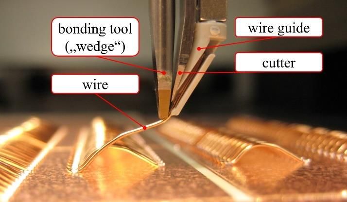
2 Smart ultrasonic welding application, not investigated here, is ribbon bonding, i.e.
wire bonding with rectangular cross-section wire. The pack
In principle, most wire bonding machines could be pro- uses 4 x 6 passive (“dummy”) cells of size 21700 (21 mm
grammed to not use the wire handling functions and work diameter, 70 mm height) in a 6p4s configuration (6 cells in
as an ultrasonic welding machine with advanced function- parallel, 4 in series), resulting in a pack voltage of 4 x 3.6 V
ality. But in such a scenario, the unused wire handling com- = 14.4 V if real cells were used. It was developed by Hesse
ponents would produce unnecessary costs and limit acces- Mechatronics for demonstration purposes. Cap and crimp
sibility. Also, the maximum power of heavy wire bonders of the cells are made of nickel-coated steel, bus bars be-
is too low for most current ultrasonic welding applications. tween the cells are made of AlMgSi0.5.
Thus, there is a need for machines for what we call “smart
ultrasonic welding”, combining the force and ultrasound 3.1 Connection layout
power of conventional ultrasonic welding machines with
Referring to the top views in Figure 6, the produced inter-
the flexibility, precision, speed and process control features
connections connect the caps (positive electrodes) of the
of state-of-the-art wire bonding machines.
cells to the bus bar above and the crimps (negative elec-
These include precise positioning and rotation, pattern
trodes) to the bus bar below. Thus, 48 weld connections are
recognition to detect the exact weld location, and deriva-
needed to connect the 24 cells with pre-placed lead frames,
tion of an optimal trajectory to reach the weld location
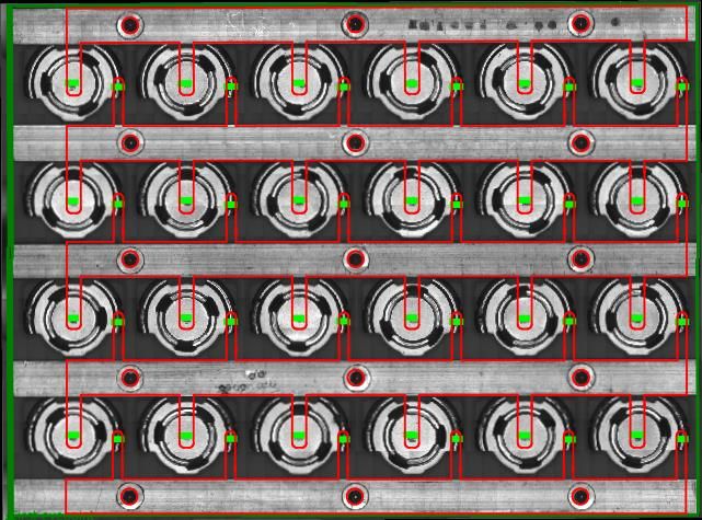
cp. Figure 7(a) and Figure 6(a). With wire bonding, lead
quickly and very precisely. Together with long and slim
frames are obsolete, but the connecting wire must also be
welding tools, this allows flexible layouts and very tight
bonded to the bus bar. So called stitch bonds are used to
spacing, and thus more compact products or higher power
connect inner bus bars with a cap and a crimp using a single
density in existing packages. Touchdown sensing, freely
wire and three bond connections. Thus, in this pack config-
programmable ultrasound and force courses, and precise
uration with four rows of six cells each, a total of 78 bond
contact force control facilitate welding on sensitive sub-
connections is needed – 24 on caps, 24 on crimps, 30 on
strates. Like ultrasonic wire bonders, smart welding ma-
bus bars, cp. Figure 7(a) and Figure 6(b). With increasing
chines can flexibly handle a large variety of products.
pack size, the share of inner bus bars increases, reducing
the share of single-connection wire bonds. The number of
3 Case study: interconnections in bonds per cell is 3+1/n, with the number of rows of cells n.
It is thus 3.25 in this example with n = 4 and approaches,
cylindrical cell battery packs but never reaches, 3.
As a case study, we present and compare wire bonding and In the welding process, any layout change requires a mod-
(smart) welding processes for a battery pack application. ification of the lead frame. With wire bonding, layout
Ultrasonic joining has some advantages over other technol- changes can be implemented in the bonding program
ogies for such applications. It does not require zero gap be- within minutes.
tween lead frame and cell like laser welding as gaps are
closed automatically during the application of the initial 3.2 Pattern recognition
normal force, and it can handle high tolerances in height, Positioning accuracy requirements in battery pack manu-
position and orientation. It is insensitive to varying reflec- facturing are typically less tight than in electronics manu-
tivity or high thermal conductivity and has little heat effect facturing. Still, the connections must be placed at the cor-
and no heat affected zone, other than laser and resistance rect positions to ensure a stable manufacturing process and
welding. And it produces neither smoke nor splatter. The electrical functionality of the pack. This is true for both
main disadvantages of ultrasonic joining over these tech- (smart) welding and wire bonding.
nologies are that it requires clean surfaces of constant qual- In this use case, the positions of welds and wires were de-
ity and that the parts to be joined must be properly fixed for fined relative to the edges of the battery pack. Before weld-
a reliable process. ing a pack, its position is detected by pattern recognition of
The case study was conducted using a Hesse Mechatronics two corners. If necessary, e.g. in battery packs manufac-
SW955 (type D machine design, cp. Figure 1). This ma- tured with less accuracy or if a very constant process result
chine with a maximum ultrasound power of 200 W is ca- is desired, pattern recognition can also detect the individual
pable of welding copper contacts up to about 2 mm² and cells, but this takes more time and reduces throughput. Fig-
marks the low power end of a series of smart welders. This ure 6 shows the bonding/welding patterns as defined after
machine series shall provide producers of medium-sized pattern recognition.
ultrasonically welded connections with increased process Power electronics packages designed for classic ultrasonic
control and freedom of design for the next generation of metal spot welding often include large clearance to com-
power electronics, battery packs and other applications. pensate for coarse positioning of the product under a rather
Thy hybrid machine used for the tests handles both smart bulky stationary welding tip. With pattern recognition and
welding and wire bonding. precise positioning available in smart welders, these clear-
The power connections in the investigated battery pack ances can be minimized, enabling more compact designs.
have been produced using 500 µm Al (Heraeus Al-H11
CR) wire bonds and ultrasonic welds of pre-placed Al (EN
AW-Al 99.5 H12) lead frames. A third option for such an
Submitted for publication in the proceedings of CIPS 2020 – 11th International Conference
on Integrated Power Electronics Systems, Berlin, Germany, March 24–26, 2020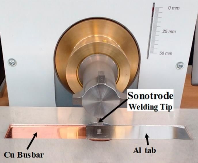
be expected for a well-developed industrial process and not
suitable for a realistic comparison. Especially the material
of the lead frame appeared to be critical.
Assuming welding times of 0.3 s for cap and crimp con-
nections and 0.15 s for the simpler (Al on Al, rigid sub-
strate) bus bar connections, an industrial smart welding
process would take 21.2 s, while wire bonding would take
34.8 s, i.e. 64 % longer. But any comparison must consider
the longer process chain of smart welding, including lead
frames placement, and the desired tact time in relation to
automation and loading. A practical comparison should
also always use real welding times and consider required
contact areas. In the investigated example, wire bond con-
tact areas are about 0.5 mm², while lead frame welds are
(a) smart welding process about 1.3 mm².
3.4 Quality control
As an example, the PiQC system described in section 1.4
has been applied to the 24 cap welds with the tolerance
set to 0 for demonstration purposes. A tolerance setting
of = 0 means that even the smallest deviation from the
learned reference results in a quality index below 100 %,
cp. Figure 5. This is not practical for productive use, but
makes the variation within the group of good welds visible,
which would otherwise all have a quality index of 100 %.
Figure 8 shows the calculated total quality indices. The
threshold was set to 50 %, thus the system in production
mode would identify one weld (with quality index 48.8 %)
as “bad”, marked in yellow in Figure 8.
(b) wire bonding process
Figure 6 Screenshots showing positions of planned welds
(green) and wires (yellow) after the pack position has been
detected by pattern recognition; smart welding screenshot
augmented with overlay of lead frame contours (red). 1 1 1 1 6 3 6 4 1
40 50 60 70 80 90 100 %
Figure 8 Histogram of calculated total quality indices of
cap welds, with sensitivity s = 50 % and tolerance = 0.
Looking at the individual quality indices, cp. Figure 9, it
becomes obvious that the main driver for identification of
the weld as “bad” is its poor wire deformation quality index
(a) (b) of almost 0, but that its other quality indices are also at the
Figure 7 Details of battery packs produced by (a) welding lower edge of the investigated set. In fact, the raw wire de-
of pre-placed lead frames, (b) wire-bonding formation signal, cp. Figure 10, shows a significantly dif-
ferent course especially in the second process phase (after
0.5 s). Other deviations leading to low quality indices can
3.3 Process time
be much less obvious, but still indicate a significantly dif-
Because welding with pre-placed lead frames requires less ferent, i.e. worse, process result. This example demon-
welds and no looping or cutting, process time excluding the strates that Process integrated Quality Control provides a
welding process is much shorter, with 6.8 s for smart weld- reliable and time-efficient non-destructive method for
ing and 15.9 s for wire bonding on a Hesse Mechatronics 100 % quality control in smart ultrasonic welding equip-
SW955 operating at full speed with the same typical set- ment.
tings for touchdown velocity and height.
The required welding times are highly dependent on the
materials of the contact partners and on the vibration char-
acteristics of the substrates, they can differ by 100 % and
more. The materials used in this case study were not ideal,
thus the achieved welding times are longer than what can
Submitted for publication in the proceedings of CIPS 2020 – 11th International Conference
on Integrated Power Electronics Systems, Berlin, Germany, March 24–26, 2020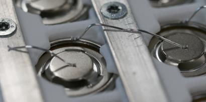
successfully [11, 12] and is expected to soon be available
                                                                     in commercial equipment.
Quality index

                                                                     5      Literature
                                                                     [1] Matheny, M. P.; Graff, K. F.: Ultrasonic welding of
                                                                          metals. In: Power Ultrasonics: Elsevier, 2015, p. 259–
Figure 9 Boxplots of individual quality indices, with the                 293. DOI:10.1016/B978-1-78242-028-6.00011-9
“bad” weld marked in red                                             [2] Rozenberg, L.; Wood, James S.: Physical Principles
                                                                          of Ultrasonic Technology. Springer, New York, 1973
                                                                     [3] Das, A.; Barai, A.; Masters, I.; Williams, D.: Compar-
deformation / mm

                                                                          ison of Tab-To-Busbar Ultrasonic Joints for Electric
                                                                          Vehicle Li-Ion Battery Applications. World Electr.
                                                                          Veh. J., 2019, 10, 55. DOI:10.3390/wevj10030055
                                                                     [4] Harman, G.: Wire Bonding in Microelectronics, 3rd
                                                                          ed., McGraw-Hill, New York, 2010
                                     time / s                        [5] Wodara, J.: Ultraschallfügen und -trennen. DVS-Ver-
Figure 10 Vertical deformation of all 24 welds over weld                  lag, Düsseldorf, 2004 (in German)
time, with the “bad” weld marked in blue                             [6] Siepe, D., Bayerer, R., Roth, R.: The future of wire
                                                                          bonding is? Wire bonding!, Int. Conf. on Integrated
                                                                          Power Electronics Systems (CIPS), Nuremberg, Ger-
4                  Conclusion and outlook                                 many, 2010
                                                                     [7] Brökelmann, M.; Siepe, D.; Hunstig, M.; McKeown,
In this contribution, we compared the ultrasonic joining
                                                                          M.; Oftebro, K.: Copper wire bonding ready for in-
technologies of classic ultrasonic spot metal welding, wire
                                                                          dustrial mass production. 48th Int. Symp. on Microe-
bonding, and smart welding and investigated their feasibil-               lectronics (IMAPS), Orlando (FL), USA, Oct. 26-29,
ity power electronics packaging, as opposed to classic ul-                2015. DOI:10.4071/isom-2015-WP32
trasonic metal spot welding. Smart welding machines pro-
                                                                     [8] Yole Développement. Report Sample: Li-ion Battery
vide a significant advantage over classic ultrasonic metal
                                                                          Packs for Automotive and Stationary Storage Appli-
spot welding equipment regarding flexibility, precision,                  cations.     2018       https://www.i-micronews.com/
speed and process control. In these regards, including ad-                produit/li-ion-battery-packs-for-automotive-and-sta-
vanced quality control, smart welding is on par with wire                 tionary-storage-applications/ (accessed 2019-12-12)
bonding.
                                                                     [9] Hagenkötter, S.; Brökelmann, M.; Hesse, H.-J.: PiQC
We also smart welding and wire bonding in a battery pack                  – a process integrated quality control for nondestruc-
case study conducted on a hybrid machine. The study has                   tive evaluation of ultrasonic wire bonds. IEEE Ultra-
shown that battery packs can be produced using smart ul-                  sonics Symposium (IUS), 2008, pp. 402–405.
trasonic welding as well as using ultrasonic wire (or rib-                DOI:10.1109/ULTSYM.2008.0099
bon) bonding. Both types of machines provide identical               [10] Hagenkötter, S.; Brökelmann, M.; Hesse, H. J.: Pro-
features. Some machines, like the one used for the case                   cess integrated Wirebond Quality Control and its In-
study, even handle both processes. For these reasons, the                 dustrial Verification. European Microelectronics and
process itself is what makes one or the other the better                  Packaging Conf. (EMPC), Rimini, Italy, June 15–18,
choice for a specific industrial application.                             2009
Wire (and ribbon) bonding processes do not require a pre-            [11] Unger, A.; Hunstig, M.; Brökelmann, M.; Hesse, H.
placed lead frame. This saves the production of this part                 J.: Thermosonic wedge-wedge bonding using dosed
and the placing process. It also results in a higher flexibility          tool heating. European Microelectronics and Packag-
of the bonding process, as layout changes can be realized                 ing Conf. (EMPC), Pisa, Italy, September 16-19,
by mere programming. On the other hand, process time                      2019. DOI:10.23919/EMPC44848.2019.8951825
(without placing) for welding with pre-placed lead frame             [12] Hunstig, M.; Unger, A.; Brökelmann, M.; Hesse, H.
typically is significantly lower. Lead frames can be de-                  J.: Process advantages of thermosonic wedge-wedge
signed to have more or less any contact area, while wire                  bonding using dosed tool heating. 52nd Int. Symp. on
bonding can scale the contact area by the number of wires                 Microelectronics (IMAPS), Boston (MA), USA, Oc-
and their size, limited by wire handling.                                 tober     1-3,     2019.      DOI:10.4071/2380-4505-
Both processes can profit of the addition of heat to the pro-             2019.1.000519
cess, which can increase weld strength and/or reduce pro-
cess time. It can also increase bondability and enable pro-
cesses using materials not feasible at room temperature.
While substrate heating is impractical for battery applica-
tions and many others, direct heating of the process zone
using laser power has recently been demonstrated

                       Submitted for publication in the proceedings of CIPS 2020 – 11th International Conference
                           on Integrated Power Electronics Systems, Berlin, Germany, March 24–26, 2020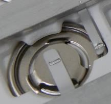
You can also read