Oakland Fire Department Bay Area Rapid Transit (BART) Manual - Effective 3/1/2021 Battalion Chief Anthony Sanders Oakland Fire BART Liaison
←
→
Page content transcription
If your browser does not render page correctly, please read the page content below
Oakland Fire Department
Bay Area Rapid Transit (BART)
           Manual

                      Effective 3/1/2021
               Battalion Chief Anthony Sanders
                  Oakland Fire BART Liaison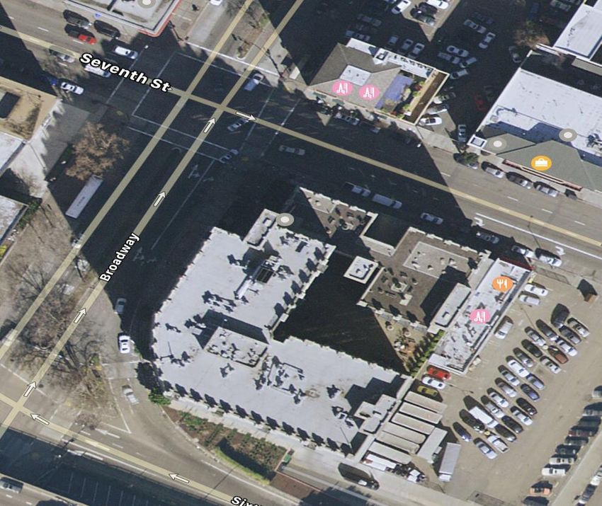
Table Of Contents                Page

 BART System Facts                1

 Orientation of BART Trackways    2

 Electrification                  9

 Fire Protection Systems         17

 The Oakland Wye                 23

 Transbay Tube                   31

 Berkeley Hills Tunnel           37

 BART Airport Connector          44
BAY AREA RAPID TRANSIT (BART) SYSTEM FACTS
BART is a 131-mile, automated rapid transit system serving more than 3.5 million
people. BART operates in five counties, Alameda, Contra Costa, San Francisco, Santa
Clara and San Mateo with an average weekday ridership exceeding 405,000.

  Lines:                Locations:
  A-Line                Oakland WYE to Berryessa/North San Jose Station
  C-Line                Oakland WYE to Pittsburg/Baypoint Station
  L-Line                Bayfair to Dublin/Pleasanton Station
  M-Line                Oakland Wye to Colma Station
  R-Line                MacArthur to Richmond Station
  W-Line                Colma to Millbrae Station

  Y-Line                San Francisco International Airport to the W-Line, Northbound connects south of San
                        Bruno Station. Southbound connects north of the Millbrae Station

Oakland Fire Department BART Manual 03/01/2021                                                           1
ORIENTATION OF BART TRACKWAYS

  Oakland is the hub of the BART system. All tracks with the exception of the Y-Line
  radiate from Oakland and are identified with Mile Post markers. Mile Post markers
  have a blue background with white reflective lettering.

  Mile Post Markers measure distance from the Line Anchor within the Oakland Wye.
  Markers on aerial or at grade track give distances every one-tenth of a mile (528 feet).
  Markers in the underground are every one-fiftieth of a mile (105 feet).

  Each track and line also has an alphanumeric identification displayed on the lower
  portion of the marker. The alpha portion designates the line over which the tracks run.
  A-Line: Oakland Wye to San Jose. C-Line: Oakland Wye to Pittsburg/Bay Point. L-
  Line: Bayfair to Dublin/Pleasanton. M-Line: Oakland Wye to Colma (Daly City Yard).
  R-Line: MacArthur to Richmond. W-Line: Colma to Millbrae (the W-Line is a
  continuation of the M-Line). Y-Line: San Francisco International Airport to Millbrae
  and San Bruno.

  In the numeric portion the odd number designates tracks where trains normally travel
  away from the Oakland Wye (and the San Francisco International Airport on the Y-Line
  only), and even numbers where they normally operate toward the Oakland Wye (or
  SFIA on the Y Line).

Oakland Fire Department BART Manual 03/01/2021                                          2
Platforms:

 Platforms are numbered to designate which direction the train normally travels. Odd
 numbered platforms are for trains traveling away from the Oakland Wye. Even
 numbered platforms are for trains traveling towards the Oakland Wye. Example: In 12th
 ST and 19th ST stations, platforms 1 & 3 are located on the same level because both
 trackways travel away from the Oakland Wye. Platform 2 is one level lower and travels
 toward the Oakland Wye.

   Revenue Vehicles:

                                            Legacy (pre 2016) Fleet
   "A"- Car: A lead car unit equipped with a double walled molded fiberglass
             operator’s cab, 4 doors, automatic train operating equipment,
             and communications system.

   "B"- Car: An intermediate car, 4 doors, without an operator's cab.

   "C"- Car: The C-car is capable of operating as a lead unit or as an intermediate
             car. Each car is equipped with 4 doors and a painted aluminum cab
             similar to the A-car to facilitate the operator's compartment. The main
             benefit of the C-car is the addition of two swing out doors (flipper
             doors) mounted in the front center of the cab which allow dual
             function. With the flipper doors closed the C-car performs as a lead
             unit, when the doors are locked open the C-car assumes the operation
             of an intermediate unit.

Oakland Fire Department BART Manual 03/01/2021                                         3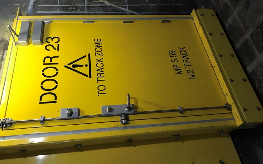
A train consists of three to ten cars. Each car is approximately 70 feet long, 10 ½ feet
 wide and 10 ½ feet high. Each revenue vehicle weighs approximately 60,000 pounds
 empty and 96,000 to 100,000 pounds at "crush" load (200 + passengers).

                                      A - Car                               C - Car

Oakland Fire Department BART Manual 03/01/2021                                         4
Legacy Vehicle Door and Window Numbering:

                                 W16                W15
                                                             Y End
                                 W14                W13

                                D4                 D3
                                                   (Barrel Key accessible)

                                W12                 W11

                                W10                 W9

                                W8                  W7

                                W6                  W5

                               D2                   D1
     (Barrel Key accessible)

                                   W2              W3

                                   W4              W1        X End
                                                                             5
Oakland Fire Department BART Manual 03/01/2021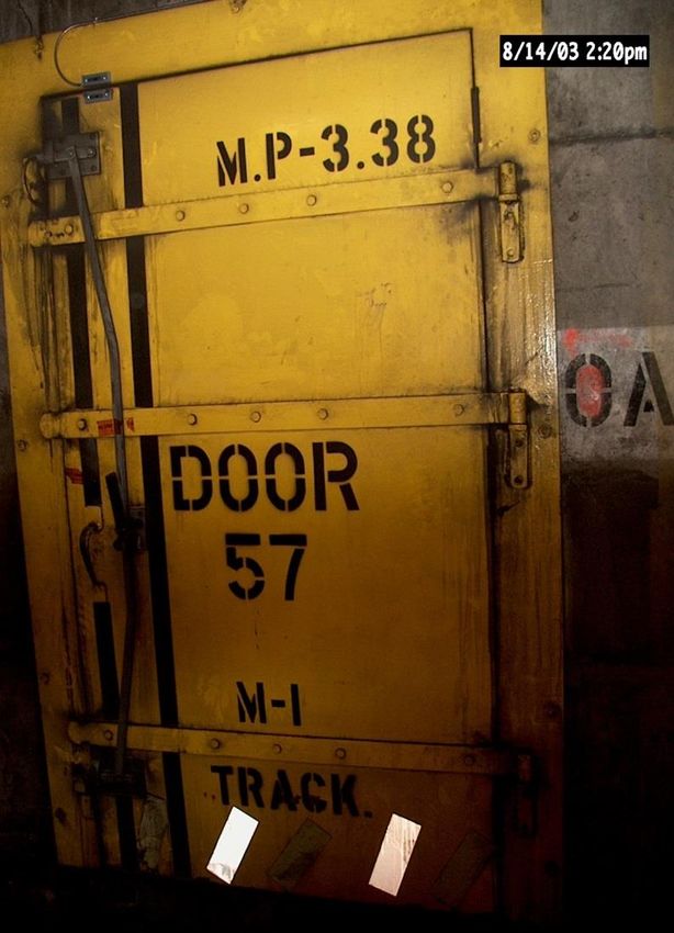
Next Generation (post 2016) Revenue Vehicles:

“D”- Car: Next Generation revenue vehicle with 6 doors capable of operating as a
          lead unit or as an intermediate car. They have a capacity of 241
          passengers.

“E”- Car: Next generation revenue vehicle with 6 doors that operates as an
          intermediate car, without an operator’s cab. They have a capacity of 256
          passengers.

Patrons can walk between “D” and “E” cars, they however cannot pass from “D” car to
“D” car unless they have a BART Barrel key.
A train consists of three to ten cars. Each car is approximately 70 feet long, 10 ½
feet wide and 10 ½ feet high. Each revenue vehicle weighs approximately 65,500
pounds empty and up to 110,000 pounds at "crush" load (“D” car 241 and “E” car
256). A ten car train at “crush” load can have 2,530 passengers.

Oakland Fire Department BART Manual 03/01/2021                                        6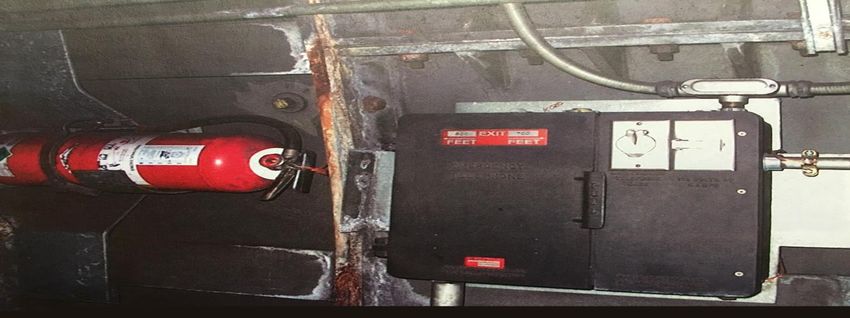
Next Generation Vehicle Door and Window Numbering:

                                                             Y End
                                     W16         W15

                                     W14         W13

                                     D6          D5
                                                 (Barrel Key accessible)

                                   W12           W11

                                   W10           W9

                                     D4          D3
                                     W8          W7

                                     W6          W5

                                   D2            D1
       (Barrel Key accessible)

                                     W4          W3

                                     W2          W1
                                                             X End
Oakland Fire Department BART Manual 03/01/2021                             7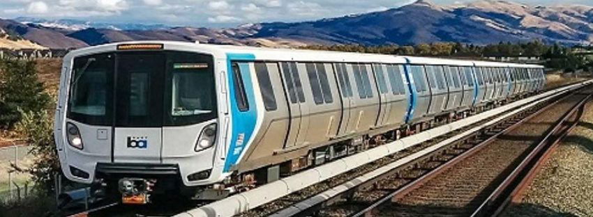
Common Features of Legacy and Next Generation Revenue
Vehicles:
Numbe ring – All BART Cars have a unique number, the number is posted at the base on all
4 corners of the vehicle and on the roof of the vehicle on the “X” end. The cars ends are
indicated with either an “X” or “Y” following the car number. The “Y” end is the end
containing the operator’s cab.
Powe r – 37.5V DC Nickel Batteries power emergency lighting, communications, door
operations, and other auxiliary power. Battery power can last for up to 2.5 hours after 3rd rail
power loss.
Braking – The friction braking system operates using hydraulic fluid with an operating
pressure as high as 2250psi, at each end of the car are a control unit, pump and
accumulator. The brake pads are similar to those used in the automotive industry. Brakes
can be prone to overheating and smoking.
Compressed Air – Compressed air on board is used in suspension and cooling electrical
components. There is one compressor in the middle of the car that feeds 6 reservoirs, 3 at
each end of the car, 1 main and 2 suspension.
HVAC – Each car contains two HVAC units that use R407c refrigerant.
Fire Retardant Foam – Undersides of cars are lined with intumescent foam sheathing that
when exposed to heat expands into a fire retardant foam. The foam provides a 30 minute fire
barrier to the floor of the car.
Access – Barrel keys will access certain exterior doors and all cabinets inside the train. Each
door is equipped with an Emergency release lever. The barrel key will release the door lock,
the unlocked door panels will need to be opened by hand. If emergency release lever is
activated while train is in motion the train will need to be stopped before the door can open.
Intercoms – There are intercoms at each exit door that communicate to the train operator. In
Next Generation vehicles, when the intercom is keyed, the on board security cameras switch
to a higher resolution.
Fire Extinguishers – One at both “X” and “Y” ends on the odd side.
Higgins Plank – Used for bridging doors between incident train on grade level and aerial
trackways. Planks are stored in the “X” end of cars on the odd side. Plank capacity 550lbs at
center.
Wheel Chocks – Stored in the “X” end of cars on the odd side with Higgins plank.
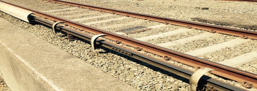
Oakland Fire Department BART Manual 03/01/2021 8ELECTRIFICATION BART revenue vehicles operate on 1000 volts (V) direct current (DC) traction power supplied by the electric third rail. The 1000 V DC is fed through circuit breakers to the various electric third rail sections. Gap breaker stations allow sections of electric third rail to be isolated or connected. Station power, (480 V AC), is supplied by PG&E. Traction Power: Power for the BART system is received from PG&E as 115 kV or 34.5 kV AC through "Switching Stations" located throughout the system. 115 kV power is reduced to 34.5 kV. The 34.5 kV power is then transmitted to "Substations" located near passenger stations, or underground installations. 34.5 kV for the BART system is transmitted along the trackway in two ways. At-grade level, the cables are buried underground next to the trackway. A concrete cover provides additional protection. Cables running through the aerial, subway and-tunnel sections are sealed inside a four-inch pipe pressurized with nitrogen gas for protection and moisture control. Although the pipe can be damaged, they don't pose a great danger. If the cables are exposed or damaged in any way they should be treated as a High Voltage emergency. Substations convert the 34.5 kV AC to 1000 V DC and supply it to the third rail. Third Rail: The third rail is a steel and aluminum composite I-Beam mounted on ceramic insulators and a metal base bolted to the trackway or cross ties. All third rail sections are shielded by fiberglass coverboards, which are rated to support 200 pounds (when new). The third rail is laid out in sections throughout the system. The sections vary in length from 150 feet to several miles. Oakland Fire Department BART Manual 03/01/2021 9
Third Rail (continued):

  A bridgeable gap is a physical separation of the third rail less than 55 feet, the distance
  between collector shoes on a BART revenue vehicle. This means a revenue car can
  be parked so that it spans the bridgeable gap and could possibly carry power from a
  collector shoe on an energized third rail section to a collector shoe in a de-
  energized section. BART has addressed this by setting up zones in these areas such
  that when "Power Off' is requested, all third rail power on both sides of the section
  requested is in a power off status to the nearest non-bridgeable gap.

Oakland Fire Department BART Manual 03/01/2021                                            10
A non-bridgeable gap is a physical separation of third rail sections greater than 55 feet.
  As stated previously, the distance between collector shoes on a revenue vehicle is 55 feet,
  which means third rail power (1000 V DC) cannot be passed from an energized section to
  a non-energized section of third rail.

                                                         Collector shoes capacitors
                                                         store 1000 V DC current
                                                         for 5 minutes after 3 rd rail
                                                         power has been cut.

                                                           DO NOT TOUCH
                                                         COLLECTOR SHOES

  3rd rail power is not transferred from car to car. The four collector shoes on the vehicle
  are interconnected. If a car is spanning a bridgeable gap, the 4 collector shoes ON
  THAT CAR are energized. The rest of the train on the de-energized section of rail is not
  under 3rd rail power. (See figure on next page)

Oakland Fire Department BART Manual 03/01/2021                                          11
ENERGIZED 3RD RAIL ENERGIZED 3RD RAIL
Oakland Fire Department
BART Manual 03/01/2021
The cars shaded in red are energized. Note the car
shaded red closest to the end of the platform. That
car is energized because collector shoes on that
Platform car are bridging the gap between the energized and
de-energized 3 rd rails. 3rd rail power does not
transfer from car to car.
DE-ENERGIZED 3RD RAIL ENERGIZED 3RD RAIL
12De-Energizing the Third Rail: Fire Departments can notify BART to cut power (Power Off) on any section of track by any one of the following: 1. Working through the BART Liaison (preferred method) 2. Direct phone call by Fire Dispatch to BART's Operations Control Center 3. Emergency Phone (Red Phone) in Station Agent's booth 4. Emergency Phone at Blue Light Stations. 5. Direct phone call to BART's Operations Control Center from the field Fire Department personnel can cut power to the third rail using the platform trip on station platforms or the third rail trip button at blue light stations in underground areas. BART Central must be notified immediately by any of the above listed methods when third rail power trips are used. Platform trips are located in BART Stations in the center of the platform. When tripped, power will be shut off the track adjacent to the trip. It will de-energize the entire platform and will show a “Power Off Status” in BART Central. In order to be re-energized the pin will have to be pushed back in and held in place with a new glass insert or plastic plunger. PUSHING THE PIN BACK IN DOES NOT RE- ENERGIZE THE TRACK. IT ALLOWS BART CENTRAL TO RE- ENERGIZE IT. Oakland Fire Department BART Manual 03/01/2021 13
Securing Electrical:

      Power Off Status:
      BART's definition of "Power Off' is a condition where BART Central has
      indications on their display board through remotely controlled and monitored
      equipment that circuit breakers are open and a sensor attached to the third rail is
      annunciating a power off status. Activities that may contact the third rail or other
      normally energized components can be attempted with power off status. Personnel
      should exercise extreme caution while operating in a power off status.

      Electrical Safe Clearance:
      In an event where direct contact with the third rail or collector shoe is necessary,
      BART will dispatch Electricians to establish an "Electrical Safe Clearance" WHEN
      REQUESTED. An Electrical Safe Clearance insures that the remotely controlled
      circuit breakers are physically disabled by racking them out and tagging them.

        Blue Light Station:

        • Trip buttons for de-energizing third rail sections within subway bores and
          tunnels are located in emergency panels called "BLUE LIGHT STATIONS."
          The blue light above the panel readily identifies these stations. Adjacent Blue
          Light Stations are within line of sight and not more than 1000 Feet apart.

Oakland Fire Department BART Manual 03/01/2021                                              14
• Pushing the third rail trip button will cut power to the third rail on the
adjacent track. It does not cut power to any other track. Immediately
after operating the trip, use the emergency phone to notify BART Central.
This ensures the area will remain de-energized until the incident scene is
secure and released to BART. It is possible that more than a single third rail
section could be involved in the incident. Be absolutely certain that all
involved third rail sections are de-energized prior to starting work on a
particular incident.
• Always verify "POWER OFF" with BART Central. BART Central will NOT
return power to the third rail until directed to do so by the "Incident
Commander".
• UNLIKE THE PLATFORM TRIPS, BART CENTRAL CAN RE-
ENERGIZE THE 3 RD RAIL SECTION REMOTELY WITHOUT YOU
PUSHING THE TRIP BUTTON BACK IN.
Blue Light Stations on trackways contain:
1. Emergency third rail "Power Trip Station"
2. Emergency telephone direct-connect line to BART Central.
3. Each phone has an ID number that BART Central will verify to identify the
instrument location.
4. A telephone jack for the Black Maintenance Telephone System (except on
West Bay Extension)
5. A 120 volt, 5 amp AC outlet
6. A metal plate on the exterior of the door shows distance in feet to the
closest exit in each direction
7. ABC type extinguishers are located near each Blue Light Station.
Oakland Fire Department BART Manual 03/01/2021 15Transbay Tube Blue Light Station:
Blue Light Stations in the Transbay Tube Lower Gallery contain:
1. Emergency telephone direct-connect line to BART Central.
2. Each phone has an ID number that BART Central will verify to identify
the instrument location.
3. A Fire Department Yellow Phone Jack.
Oakland Fire Department BART Manual 03/01/2021 16FIRE PROTECTION SYSTEMS
Wet Standpipe System:
All BART Station platform and concourse levels are equipped with "Class 3" wet
standpipe fire hose cabinets with both 1 1/2” and 2 1/2" outlets (exception: San
Francisco uses 3" fire hose connections). Some stations also have Stand Alone
"Class 2", 2 1/2"wet standpipe outlets for fire department use.
Fire Pumps:
Auxiliary fire pumps are located at eight BART Stations and at each end of both
the Transbay Tube and Berkeley Hills Tunnel. The capacities of these pumps
range from 100-1600 GPM and can be seen in the table below. In addition to
auxiliary pumps, all station and underground trackway water supply systems can
be supplemented by pumping into Fire Department Connections. Due to the
variations in friction loss in each station to the most distant outlets on the
platform level, it is recommended that fire departments be prepared to augment
pressure if firestreams are inadequate.
BART Auxiliary Pump Locations and Capacities:
Oakland Fire Department BART Manual 01/03/2021 17Under Car Deluge System:
The stations listed in the table below are equipped with dry "Under Car Deluge
Systems.” The purpose of these systems is to remotely pump water under BART
cars in the event of undercarriage fires on trains in stations. Each station
trackway equipped with deluge systems will contain 5 sets of dry pipe zones.
Stations in Oakland are not equipped with pre-plumbed Under Car Deluge
Systems.
To operate the deluge system, firefighters extend hose from the platform Wet
Stand Pipe outlet in the hose cabinet to the deluge inlet. Inlets and deluge pipe
sections are labeled; however, firefighters should be familiar with inlet and
corresponding deluge pipe locations, as fire conditions will make it very difficult
to see the labeling during fire attack operations.
Oakland Fire Department BART Manual 03/01/2021 18Deluge Zone signs are on posted at the marquee signs
Deluge zone breaks
Deluge outlet
Oakland Fire Department BART Manual 03/01/2021 19When hooking up to the inlets it is crucial to remember that the deluge system in
the opposite platform track from the inlet will be charged. The only exception is
in 12th and 19th ST lowest platform (Platform 2). Those connections are at either
end of the platform and supply the deluge systems on the other end of the
platform.
Warning:
Under normal fire ground procedures, power will be cut to the third rail in
stations where there is a fire in a train; however, INCIDENT COMMANDERS
SHOULD CONFIRM THIRD RAIL POWER IS OFF BEFORE
ORDERING DELUGE SYSTEMS CHARGED!
Oakland Fire Department BART Manual 03/01/2021 20Cross Passage Doors:
There are two types of cross passage doors, those that swing on hinges, and those
that slide on rollers. Swinging doors open into passageways that will not extend
into the adjacent trackway, while SLIDING DOORS OPEN DIRECTLY INTO
THE ADJACENT TRACKWAY.
Hose Yellow Fire
Jurisdiction Location Spacing Connection Phone
SFFD/OFD Transbay Tube 330’ Yes Yes
OFD Oakland Wye Variable Yes No
OFD/MOFD Berkeley Hills Tunnel 1000’ Yes Yes
Cross Passage door locations in tunnels are identified by yellow lights at the door
Oakland Fire Department BART Manual 03/01/2021 21Cross Passage door prior to
1979 Transbay Tube Fire
Oakland Fire Department BART Manual 03/01/2021 22THE OAKLAND "WYE” The Oakland "Wye" consists of seven interconnecting bores (see diagram below) that range in below grade depths of ~20' (at exit portals) to ~90' (at platform #2 of the 12th & 19th Street Stations). The Wye wet standpipe system is interconnected and has Fire Department Connections (FDCs) at the three stations (12th Street, 19th Street, and Lake Merritt) and near each of the portals. Wet standpipe outlets (2 1 / 2 ") are spaced every 250-300’; however, cross passage doors spacing is NOT consistent due to bore configuration. The bores change elevation as they go over and under each other in the underground. Incident Commanders should not assume what the head pressure is at track locations, but should be prepared to augment water pressure at the request of fire attack crews by pumping into the FDCs. If excessive firestream pressures are encountered, Incident Commanders may consider having hose lines gated back to retard fire flow. Oakland Fire Department BART Manual 03/01/2021 23
Emergency Exits in the Wye:
    BART has 3 Emergency Pedestrian Exits for the Wye. The first are the platforms
    in the 12th ST station. The second is an above ground building at 7th and
    Broadway. The third is a sidewalk hatch at 9th and Harrison. These exits are
    located where trackways in the Wye come together. As a responder, you may enter
    any of these points and have access to 4 of the 7 trackways in the Wye.

      7th / Broadway Emergency Exit

                                                          7th / Broadway exit provides
                                                          Emergency Personnel access to
                                                          the A and M line.

Oakland Fire Department BART Manual 03/01/2021                                        24
9th / Harrison Emergency Exit – In front of 317 9th ST
The 9th and Harrison exit gives
Emergency personnel access to the
C and A lines
Turn
Key to open hatch
to open
Oakland Fire Department BART Manual 03/01/2021 2512th ST Station Platform - gives Emergency Personnel access to the C and M lines
Wye Portals:
5th AVE Portal – Located at the intersection of E8th ST and 5th AVE
A1
A2
A2
A1
Oakland Fire Department BART Manual 03/01/2021 26Clay ST Portal – Located at the intersection of 5th ST and Clay ST
M1
MX
M2
M1
MX
M2
Oakland Fire Department BART Manual 03/01/2021 2723rd / Northgate Portal – Located at the intersection of 23rd ST and Northgate
AVE
C1 C2
CX
C2 CX C1
Oakland Fire Department BART Manual 03/01/2021 28Surface Command Posts:
Surface Command posts are used during a BART incident within the Oakland
Wye. The command post has keys to access any doors or areas associated with
that command post. Surface command posts for the Wye will also have
laminated maps of the Wye in the key box for Fire Department crews to take
inside with them.
Surface command posts are located at street level at the following locations:
19th St Station – In front of 1930 Broadway
12th ST Station – In front of 1220 Broadway
7th & Broadway Emergency Exit – Across Broadway from OPD Admin
9th & Harrison Emergency Exit – In front of 317 9th ST
Lake Merritt Station – 8th & Oak ST across from 101 8th ST
Oakland Fire Department BART Manual 03/01/2021 29Ventilation in the Wye:
The Wye has 20 fans that move 80 -100,000 CFM of air. The fans are remotely
controlled by BART Central. The fans work in a supply (push) and pull (exhaust)
fashion. Providing BART Central with the exact mile post location of the fire will
provide BART the information needed to coordinate ventilation with rescue and
fire attack. Smoke is exhausted through grates in the streets.
Oakland Fire Department BART Manual 03/01/2021 30TRANSBAY TUBE
The Transbay Tube is composed of fifty-seven steel and reinforced concrete
sections, each averaging 330’ in length. It is approximately 3.5 miles in length
with a continuous walkway on one side of each bore and cross-passage doors at
nominal 330-foot intervals. The Tube is connected at each end to a ventilation
structure. There are two chambers between the trackways. The upper chamber is
an exhaust duct and the lower a utility gallery. Both chambers run throughout the
length of the Tube.
Oakland Fire Department BART Manual 03/01/2021 31The utility chamber, or lower gallery, allows access and egress between each
trackway through the cross-passage doors. The lower gallery also provides
access and egress with the surface through either vent structure. Personnel
moving between the incident and non-incident bores must ensure the cross-
passage door(s) on one side are closed prior to opening the opposite side
door(s). With doors to both bores open smoke can migrate into the non-
incident bore through the lower gallery and contaminate the non-incident bore.
The exhaust duct has remotely operated dampers to each trackway at 1000-
foot intervals. Each damper is numbered. Crews should confirm with
BART central that the desired dampers are open. The exhaust duct is
routed to a pair of exhaust fans at each vent structure.
Smoke and heat are "pulled" from the trackway by opening the proper damper
and turning all four fans to "EXHAUST." The open damper is the one that will
"pull" the smoke away from the greatest number of patrons/cars.
Oakland Fire Department BART Manual 03/01/2021 32When the fans at the vent structures are in exhaust mode, replacement air is drawn down the trackway from the relief shafts at both vent structures and the bore entrances on the Oakland and Embarcadero side. The lower gallery in the Transbay Tube is supplied with air from a pair of fans, independent of the main ventilation fans, one in each of the vent structures. Both the San Francisco and Oakland vent f ans operate in the supply mode. These fans maintain positive pressure in the lower gallery. The water supply to the Transbay Tube consists of an 8” inch main supplied from both the San Francisco and Oakland sides, with 3" outlets in both bores at cross passage doors every 330'. The water main is a wet system with three motor operated valves. One is at either end of the Tube in the Oakland and San Francisco Vent Structures, and the third is in the center of the Tube (in the upper gallery). Although this is a wet system, these valves remain CLOSED until there is a fire or other event that requires they be opened, such as service and testing. These valves are remotely opened by BART Central when water is needed; however, they may be operated locally by fire personnel by either switching from remote to local control and turning on the motor to open the valve, or by disengaging the motor and operating the valve manually. The valves are standard 0S&Y's. Oakland Fire Department BART Manual 03/01/2021 33
There are two auxiliary pumps, connected in parallel, in each vent structure with 500
   GPM capacities. Whether activated remotely by BART Central or locally by fire
   personnel, they can be turned on individually or together. When both are turned on,
   they deliver 1000 GPM.

   At the lowest point of the Tube, there is over 60 psi of head pressure, and there are
   no pressure reduction valves in the system. Incident Commanders may consider
   having hose lines gated back to retard fire flow.

   Fire Department Connections are located at both the San Francisco and Oakland Vent
   Structures to augment the pressure if needed. However, due to the extreme head
   pressure in the Tube, the only reason for augmenting pressure by the Fire
   Department(s) would be in the event of a total loss of domestic water supply. In that
   event, the Fire Department Connections on the San Francisco side of the Tube are
   adjacent to the bay and could be supplied either by SFFD Fire Boat or by drafting.

Oakland Fire Department BART Manual 03/01/2021                                        34
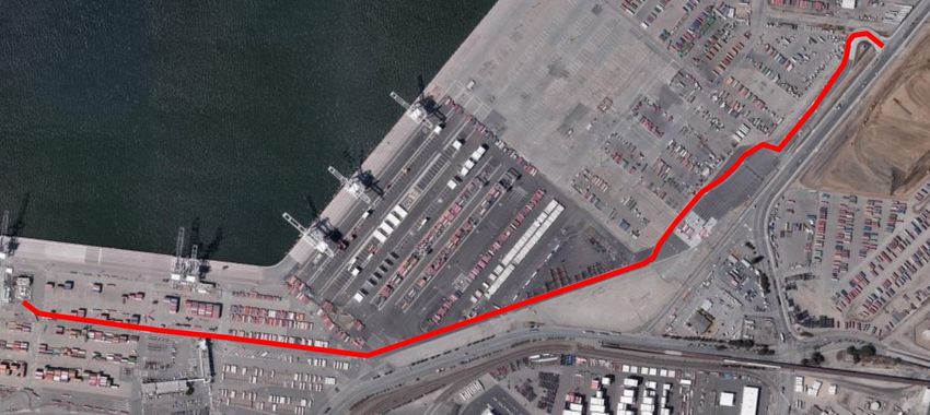
Enter Trapac terminal at 1155 Maritime
                                                                                 Follow red line to vent structure

Oakland Fire Department BART Manual 03/01/2021
                                                 TBT Ventilation
                                                   Structure

                                                                   Secondary TBT Command Shack

35
Cross Passage Doors:
Cross passage doors are spaced 330’ apart. There are 57 cross passage doors in the
Transbay Tube. They are numbered 1 through 57, starting at the San Francisco vent
structure and ending at the Oakland vent structure. Cross passage doors are self-
closing and swing on hinges into the gallery between the two bores.
It will identify what door
number it is.
Cross passage doors will indicate
the distance from the door to the
line anchor in the Wye.
What trackway you will be
entering.
Oakland Fire Department BART Manual 03/01/2021 36BERKELEY HILLS TUNNEL
The Berkeley Hills Tunnel is a twin bore tunnel between the Rockridge and
Orinda Stations approximately 3.2 miles in length.
Unlike the Transbay Tube that has a center gallery running the length of the tunnel,
the Berkeley Hills Tunnel has a continuous walkway on the ins ide wall of each
bore and cross passages at 1000 foot intervals.
Oakland Fire Department BART Manual 03/01/2021 37There are 27 cross passages,
beginning with number one (1)
starting on the Oakland side of the
tunnel. Inside the bores are signs
indicating the direction of travel and
distance to the nearest cross passage
doors.
Door from Trackway Door from cross
to cross passage passage to Trackway
Blue Light Stations in BHT:
1. Placard indicating distance to exit
2. 3rd rail trip
3. Direct connect phone to BART Central
4. Maintenance phone jack
5. 115V 5 amp plug
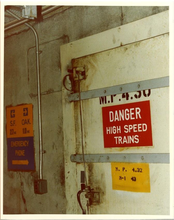
Oakland Fire Department BART Manual 03/01/2021 38Ventilation:
Each bore of the East Portal Structure houses rolling metal doors that must be
closed before activating the ventilation fans (see picture below). Four emergency
ventilation fans are located in the East Portal Structure; two for each bore. Each
bore may be ventilated independently. BART Central must ensure there are no
trains near the east portal before the rolling metal doors can be closed and
ventilation started. Once doors are closed, fans may then be activated in either the
supply or exhaust mode.
The photo below is the East Portal of the C2 trackway with the roll up door open.
For fires on the west (Oakland) end of trains in this tunnel, fans will be turned
on in the SUPPLY mode. For a fire on the east (Orinda) end of trains in the
tunnel, the fans will be turned on in the EXHAUST mode.
Oakland Fire Department BART Manual 03/01/2021 39If the fire is mid-train, the instructions are to clear smoke away from the
end of the train that is the greatest distance from a cross-passage door.
Unlike the Transbay Tube, there is no separate ventilation corridor, and no
blast dampers for smoke to be removed from the tunnel. Smoke will have
to be pulled over a section of the train and remain in the tunnel until
exhausted at the portals.
ONCE CLOSED, THE ROLLING METAL DOORS SHOULD NOT
BE OPENED IF VENTILATION IS TO SUCCEED. The Berkeley Hills
Tunnel rises 250’ between the Rockridge and Orinda portals. If the fans
were operating in the "push" mode (east to west-downhill) and the rolling
metal door were opened, the chimney effect could override the fans and
reverse the direction of the smoke flow.
West Portal at MW9
Oakland Fire Department BART Manual 03/01/2021 40Water Supply and Fire Suppression Systems:
There are 2 1/2" wet standpipe outlets spaced every 250’. The major concern with
the Berkeley Hills tunnel is that there is an elevation drop of approximately 250’
from the Orinda to the Oakland ends of the tunnel.
There are NO pressure reduction valves in the tunnel.
The Orinda and Oakland Incident Command Posts are equipped with tunnel maps
that indicate vertical pressure zones (based on milepost markers). If it is necessary
for fire-attack line pressures to be increased, the maps indicate what pressures must
be pumped into the Fire Department Connections to achieve needed nozzle
pressures for each vertical pressure (milepost) zone.
If the pressure needs to be augmented, either side of the tunnel could supply
the pressure. Examples:
1. Orinda would have to pump 135 psi to supply the Orinda end of the tunnel,
and 70 psi to augment the Oakland end of the tunnel.
2. Oakland would have to pump 150 psi to supply the Oakland end of the
tunnel, and 250 psi to augment the Orinda end of the tunnel.
Oakland Fire Department BART Manual 03/01/2021 41Significant Considerations forthe Berkeley Hills Tunnel:
1. (Oakland) Incident Commanders should consider if it is safe to pump
into supply lines at pressures equal to the maximum test pressure of our
hose for extended periods.
2. During fire attack, lines may have to be gated back to achieve effective
firestreams and prevent injuries to firefighters.
Oakland Fire Department BART Manual 03/01/2021 42Berkeley Hills Tunnel Fire Department Planning Chart Oakland Fire Department BART Manual 03/01/2021 43
BART AIRPORT CONNECTOR

      The BART Airport Connector (BAC) is 3.2 miles long and runs from the
      Coliseum Station platform to the Oakland Airport along Hegenberger
      RD. The Airport Connector line designators are: H1 Line traveling
      towards the airport, and the H2 line traveling towards Coliseum Station.

      Propulsion:

      Unlike conventional BART trains that utilize electricity to power the car
      movement, the Airport Connector system utilizes a cable pull to move
      the cars along the trackway. The wheelhouse for the cables is located at
      70 Hegenberger Rd.

Oakland Fire Department BART Manual 03/01/2021                                    44
The wheelhouse is the mid-point of the system. Each trackway has a cable
running from the wheelhouse to Coliseum Station and another cable running
from the wheelhouse to the Airport for a total of 4 motors running the 4 sets of
cables.
Oakland Fire Department BART Manual 03/01/2021 45The wheelhouse also serves as the maintenance shop for the BAC. The drawing
below shows the active trackway shaded in red, and the maintenance rails with
spare trains in the interior section. The active trackway are on the exterior of the
building and the maintenance area is housed inside on the third floor of the
facility.
Operations Control Center:
The Airport Connector has an Operations Control Center (OCC) independent of
BART Central. Incidents on the Airport Connector will have BART liaisons and
representatives responding like any other BART incident. If there is a need to
contact OCC directly for power and other items, personnel will need to contact
the BART Airport Connector OCC for those requests.
Oakland Fire Department BART Manual 03/01/2021 46Electrification:
Though the trains are moved by a cable system, there is a 3rd rail
powered with 480V DC. The 3rd rail provides power to the car for
lighting, ventilation, door controls, etc., inside the car.
Orientation of Trackway and Access:
The Airport Connector has a combination of at grade, below grade and
elevated trackway sections. All pillars are numbered and placarded with
the mile post and track identifier. The mile post markers start at 0.0 at
Coliseum and increase until terminating at mile post 3.2 at the Airport
Station.
Oakland Fire Department BART Manual 03/01/2021 47There is a continuous walkway between the 2 trackways. Access to these areas
is possible at the following locations:
1. Coliseum Station
2. EE-E Exit at MP.092 (adjacent to SB880 off ramp at Hegenberger RD)
3. Wheelhouse at 70 Hegenberger RD
4. Near intersection of Airport DR / Ron Cowan PKWY
5. Airport Station
1
2
3
4
5
Oakland Fire Department BART Manual 03/01/2021 48Access to trackway at Hegenberger Off ramp / Hegenberger RD Oakland Fire Department BART Manual 03/01/2021 49
BAC Revenue Vehicles:

     During revenue hours, there are 3 trains of 3 cars operating: one on the H1 track,
     one on the H2 track, and one in transition between the stations. The trains start
     with one at the Coliseum Station and one at the Airport Station. They travel on
     their respective trackways and pass each other near the wheelhouse ending at the
     opposite station.

     The design of the system is such that same side of the train is accessed by
     passengers at both Airport and Coliseum platforms. Both sides of the cars have
     doors, however the other doors are there for emergency use only.

     Though there are 3 cars in the train consist, you can walk from one end of the train
     to the other without passing through doors, similar to 2 car AC Transit buses.

Oakland Fire Department BART Manual 03/01/2021                                              50
The 3rd Rail Collector is “U” shaped with 4 collectors (2 hot, 1 neutral and 1
ground)
Beneath the car is the cable grip mechanism that attaches to the cable and pulley
system
Oakland Fire Department BART Manual 03/01/2021 51Each car has 2 Emergency Telephones
for a total of 6 on each train.
When activated, phones have a direct
connection to the Airport Connector
OCC.
There are also 5 cameras inside the
train, 2 in each end car, and 1 in the
middle car.
Each car has a fire extinguisher for a total of 3 on each train.
Oakland Fire Department BART Manual 03/01/2021 52BAC Train cars have manual release
handles. When activated, the doors
are able to be opened manually.
Oakland Fire Department BART Manual 03/01/2021 53Water Supply:
The BAC has a wet standpipe system with 2 ½” outlets in the walkways of the
elevated trackway every 250’. FDCs are available to augment the system at
stations and access points to the trackway.
Emergency Operations:
The BAC is a fully automated system, meaning there are no train operators. All
train controls are initiated and executed at the OCC. In the event of a fire or
emergency, the trains will automatically return to the closest of the 5 access and
exit points of the system.
Blue Light Stations:
Blue Light Stations are spaced 1000’ apart or within line of sight. Each Blue
Light Station has an identifier, communication to OCC, and 3rd rail and cable trip.
When activated, the 3rd rail and cable trip cuts power to the entire cable and
section. In order to restore power and propulsion, the switch must be reset before
the OCC can restore power.
Oakland Fire Department BART Manual 03/01/2021 54End of Document Oakland Fire Department BART Manual 03/01/2021 55
You can also read