Sonata System Service Manual - Gynesonics
←
→
Page content transcription
If your browser does not render page correctly, please read the page content below
Sonata System Service Manual
For
Sonata System 2.1 and Sonata System 2.2
SONATA2-110 with software SW-002

Manual Catalog #: REF-011US.
LS 06311-002US Rev A, January 2021
Notice
Sonata® System 2.1 and Sonata System 2.2 Service Manual
© 2021 Gynesonics, Inc. All Rights Reserved
The Sonata System and accessories, including the associated hardware, software, and Intrauterine
Ultrasound Probe, is owned by Gynesonics®, Inc. and is protected by the United States copyright
laws and international treaty provisions. This manual may not be copied in whole or in part or
reproduced without the written permission of Gynesonics, Inc. Copying includes translation into
another language and transferring into other media. Permitted copies must carry the same
proprietary and copyright notices as were affixed to the original under the law. Please note that
while every effort has been made to ensure that the information in this document is accurate, the
instructions, photos, figures, illustrations, tables, specifications, and schematics contained herein are
subject to change without notice. If you have any questions regarding the appropriate use of this
device or concerning any safety or operating instructions described in this manual, or for additional
copies of this manual, please contact your local Gynesonics Representative or the service
department of Gynesonics at:

Gynesonics, Inc.
600 Chesapeake Drive
Redwood City, CA 94063 USA
Telephone: +1-650-216-3860
Fax: +1-650-299-1566
www.gynesonics.com
UScustomerservice@gynesonics.com

Trademark and Patent Information
Gynesonics, Sonata, and the logo forms of the foregoing are trademarks and registered trademarks
of Gynesonics, Inc. All other trademarks are properties of their respective owners. Gynesonics
products are covered by US and foreign patents. See www.Gynesonics.com/patents.

About this Instruction Manual
This Manual covers the routine inspections and checks that may be performed of the Sonata System.
Refer to the Sonata System 2.1 or Sonata System 2.2 Instructions for Use with Technical Appendix for
detailed information regarding the Sonata System. Contact Gynesonics for additional copies of this
manual, any additional questions or support required for training and service, including installation,
and maintenance.
Manual originally issued in English.

LS 06311-002US Rev A
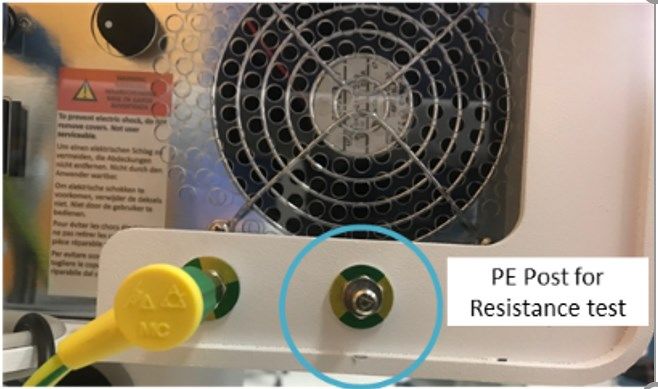
Table of Contents

Table of Contents
Symbols Glossary ........................................................................................................... ii
Glossary of Terms, Acronyms, and Definitions ........................................................ vii
Chapter 1 Introduction ................................................................................................ 10
    1.1    Manufacturer .......................................................................................................................... 10
    1.2    Device Intended Use .............................................................................................................. 10
    1.3    Room Requirements............................................................................................................... 10
    1.4    System Overview ................................................................................................................... 11
    1.5    Standards ................................................................................................................................ 13
    1.6    Reference Documents ............................................................................................................ 14
    1.7    Personnel Qualification and Service Documentation ............................................................ 14
    1.8    Tools Recommended for Service ........................................................................................... 15
Chapter 2 Electrical Safety Tests................................................................................ 16
    2.1    Visual Inspections .................................................................................................................. 17
    2.2    Insulation Resistance ............................................................................................................. 17
    2.3    Earth Leakage and Touch Current ......................................................................................... 19
    2.4    Patient Lead Leakage ............................................................................................................. 21
    2.5    Temperature Sensing Accuracy Check .................................................................................. 22
Chapter 3 Troubleshooting ......................................................................................... 24
Chapter 4 Field Replacement and Software Upgrade ............................................. 25

LS 06311-002US Rev A                                                                                                                                  i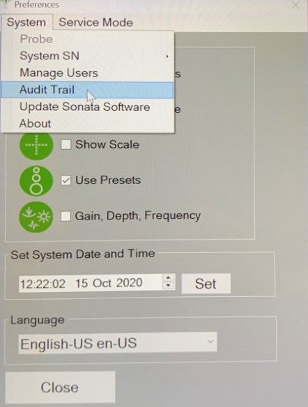
Symbols Glossary

Symbols Glossary
The following tables show the safety symbols that are used on the Sonata System and throughout
this manual.

                          SYMBOL           EXPLANATORY            STANDARD
    SYMBOL                                                                           STANDARD TITLE
                           TITLE               TEXT               REFERENCE
                                                                                 Medical devices — Symbols to
                                                                  ISO 15223-1    be used with medical device
                                                                  #5.1.1         labels, labeling, and
                                          Indicates the medical                  information to be supplied.
                       Manufacturer
                                          device manufacturer.                   Symbols for use in the labeling
                                                                  EN 980 #5.12
                                                                                 of medical devices.
                                                                  ISO 7000 -     Graphical symbols for use on
                                                                  3082           equipment.
                                                                                 Medical devices – Symbols to
                                                                  ISO 15223-1    be used with medical device
                                          Indicates the date      #5.1.3         labels, labeling, and
                       Date of            when the medical                       information to be supplied.
                       Manufacture        device was                             Symbols for use in the labeling
                                                                  EN 980 #5.6
                                          manufactured.                          of medical devices.
                                                                  ISO 7000-      Graphical symbols for use on
                                                                  2497           equipment.
                                                                                 Medical devices – Symbols to
                                          Indicates the           ISO 15223-1    be used with medical device
                                          manufacturer’s          #5.1.6         labels, labeling, and
                       Catalogue          catalogue number so                    information to be supplied.
                       number             that the medical                       Symbols for use in the labeling
                                                                  EN 980 #5.10
                                          device can be                          of medical devices.
                                          identified.             ISO 7000-      Graphical symbols for use on
                                                                  2493           equipment.
                                                                                 Medical devices – Symbols to
                                          Indicates the           ISO 15223-1    be used with medical device
                                          manufacturer’s serial   #5.1.7         labels, labeling, and
                                          number so that a                       information to be supplied.
                       Serial number
                                          specific medical                       Symbols for use in the labeling
                                                                  EN 980 #5.5
                                          device can be                          of medical devices.
                                          identified.             ISO 7000-      Graphical symbols for use on
                                                                  2498           equipment.
                                                                                 Medical electrical equipment —
                                                                  IEC 60601-1
                                                                                 Part 1: General requirements
                                                                  Table D.2,
                       Follow                                                    for basic safety and essential
                                          Refer to instruction    Symbol 10
                       instructions for                                          performance.
                                          manual/booklet.
                       use                                                       Graphical symbols – Safety
                                                                  ISO 7010-
                                                                                 colours and safety signs –
                                                                  M002
                                                                                 Registered safety signs.

LS 06311-002US Rev A                                                                                               ii
Symbols Glossary
SYMBOL EXPLANATORY STANDARD
SYMBOL STANDARD TITLE
TITLE TEXT REFERENCE
Medical electrical equipment –
Part 2-2: Particular
requirements for the basic
High Frequency Indicates connection to
IEC 60601-2-2 safety and essential
(HF) isolated a high frequency (HF)
Copyrighted material licensed to Diane King on 08-Jun-2010 for licensee's use only. No further reproduction or networking is permitted. Distributed by Thomson Scientific, Inc., www.techstreet.com.
#201.7.2.10 performance of high
patient circuit isolated patient circuit.
frequency surgical equipment
and high frequency surgical
accessories.
To identify a Type BF
and IMMUNITY of the electrical equipment that is not ME EQUIPMENT have been
applied part complying
dversely affect the BASIC SAFETY or ESSENTIAL PERFORMANCE of the ME SYSTEM;
with IEC 60601-1.
Medical electrical equipment
Type BF refers to IEC 60601-1
Type BF have been determined not to
e electrical equipment that is not ME EQUIPMENT — Part 1: General
classification of the Table D.1.
applied part
of the ME SYSTEM to exceed applicable limits. requirements for basic safety
nature of patient Symbol 20
and essential performance.
inspection of the documents for this determination andcontact other and degree of
appropriate
s or, if this determination is not performed, by inspection of the documents from
patient protection to
risk of electrical
equipment that is not ME EQUIPMENT has been tested in accordance with shock.
this
To identify the control
or the indicator to
NDITION for ME EQUIPMENT activate a linear array
GLE FAULT CONDITION requirements of the general standard door
Linear or curved
not apply.array probe TR 60878
Graphical Symbols for
curved array for the electronic electrical equipment in
#5710
probe generation of a sound medical practice.
rking and documents field and to identify the
corresponding
utside of ME EQUIPMENT or ME EQUIPMENT parts
connector.
he outside of ME EQUIPMENT or ME EQUIPMENT parts that include To indicate
RF generally Graphical Symbols for
IEC 60878
elevated, potentially
r that apply RF electromagnetic energy for diagnosis or treatment electrical equipment in
#5140
hazardous, levels of medical practice.
STEMS that include RF transmitters or that intentionally apply RF electromagnetic
eatment shall be labeled with symbol IEC 60417-5140 (2003-04) nonionizing radiation,
for non-ionizing
aphic is shown below. or to indicate
Non-ionizing equipment or systems,
electro- e.g., in the medical
magnetic electrical area that
IEC 60417 Graphical Symbols for Use on
radiation include RF transmitters
#5140 Equipment.
e outside of ME EQUIPMENT or ME EQUIPMENT parts for whichorthe thatconnector
intentionally
tion specified in 6.2.2.2 c) is used apply RF
electromagnetic
ME SYSTEMS for which the connector testing exemption specified in 6.2.2.2 c) is
energy for diagnosis or
-5134 (2003-04) for ESD sensitivity shall be applied adjacent to each connector
mption is used. The symbol graphic is shown below. ablation.
e outside of ME EQUIPMENT and ME SYSTEMS that are specified for use only in
ation
YSTEMS specified for use only in a shielded location shall be labeled with a
be used only in the specified type of shielded location (see 5.2.2.3).
he requirements of 5.1 by inspection.
LS 06311-002US Rev A iii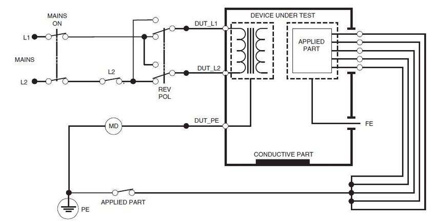
Symbols Glossary
SYMBOL EXPLANATORY STANDARD
SYMBOL STANDARD TITLE
TITLE TEXT REFERENCE
Medical electrical equipment
IEC 60601-1
— Part 1: General
To indicate hazards Table D.1
Dangerous requirements for basic safety
arising from dangerous symbol 24
voltage and essential performance.
voltages.
IEC 60417 Graphical Symbols for Use on
#5036 Equipment.
To identify the Medical electrical equipment
IEC 60601-1
terminals which, when — Part 1: General
Table D.1
connected together, requirements for basic safety
symbol 8
bring the various parts and essential performance.
of equipment or of a
Equipotentiality system to the same
potential, not
necessarily being the IEC 60417 Graphical Symbols for Use on
earth (ground) #5021 Equipment.
potential, e.g., for local
bonding.
Protected against the Medical electrical equipment
Degree of IEC 60601-1
effects of temporary — Part 1: General
Ingress Table D.3,
immersion in water. requirements for basic safety
IPX7 Protection Symbol 2
The handle and device and essential performance.
Provided by
shaft and tip are IPX 7 IEC 60529 Degrees of Protection
Enclosure
rated. section 6 Provided by Enclosures.
To identify fuse boxes Graphical symbols for
IEC TR
or their location. electrical equipment in
60878#5016
Fuse Accompanied by the medical practice.
type and full rating of IEC 60417 Graphical symbols for use on
the fuse. #5016 equipment.
Medical electrical equipment
To indicate connection IEC 60601-1
— Part 1: General
to the mains, at least Table D.1
requirements for basic safety
for mains switches or symbol 12
“ON” (power) and essential performance
their positions, and all
Graphical Symbols for
those cases where IEC 60878
electrical equipment in
safety is involved #5007
medical practice.
To indicate Medical electrical equipment
IEC 60601-1
disconnection from the — Part 1: General
Table D.1
mains, at least for requirements for basic safety
symbol 13
“OFF” (power) mains switches or their and essential performance.
positions, and all those Graphical Symbols for
IEC 60878
cases where safety is electrical equipment in
#5008
involved. medical practice.
To identify the switch Medical electrical equipment
IEC 60601-1
or switch position by — Part 1: General
Table D.1
means of which part of requirements for basic safety
symbol 29
Stand-by the equipment is and essential performance.
switched on in order to Graphical Symbols for
IEC TR 60878
bring it into the stand- electrical equipment in
#5009
by condition. medical practice.
LS 06311-002US Rev A iv
Symbols Glossary

                         SYMBOL            EXPLANATORY             STANDARD
   SYMBOL                                                                             STANDARD TITLE
                          TITLE                   TEXT             REFERENCE
                                         To indicate that
                                         caution is necessary                      Medical electrical
                                         when operating the        IEC 60601‐1     equipment — Part 1:
                                         device or control         Table D.1       General requirements for
                                         close to where the        symbol 10       basic safety and essential
                                         symbol is placed, or                      performance.
                                         to indicate that the
                       Caution
                                         current situation         ISO 7000‐       Graphical symbols for use
                                         needs operator            0434A           on equipment
                                         awareness or
                                         operator action in
                                         order to avoid
                                         undesirable
                                         consequences.
                                                                                   Medical electrical equipment
                                                                   IEC 60601-1
                                                                                   — Part 1: General
                                                                   Table D.2
                                                                                   requirements for basic safety
                                                                   symbol 2
                                                                                   and essential performance.
                       General           To signify a general
                                                                                   Graphical symbols – Safety
                       warning sign      warning.                  ISO 7010
                                                                                   colours and safety signs –
                                                                   W001
                                                                                   Registered safety signs.
                                                                                   Graphical symbols for use on
                                                                   ISO 7000-2621
                                                                                   equipment.
                                         Indicates that the
                                         product was tested and
                                         met the certification
                       TUV Mark                                    N/A             N/A
                                         requirements for
                                         electrical, and/or
                                         mechanical products.
                                                                                   Marking of Electrical and
                       Recycle:          DO NOT dispose of         Directive
                                                                                   Electronic Equipment in
                       electronic        electronic equipment in   2012/19/EU
                                                                                   accordance with Article 15 (2)
                       equipment         normal trash.             Annex IX
                                                                                   of Directive 2012/19/EU
                                                                                   Medical devices – Symbols to
                       Authorized        Indicates the             ISO 15223-1     be used with medical device
                       representative    authorized                #5.1.2          labels, labeling, and
                       in the European   representative in the                     information to be supplied.
                       Community         European Community.                       Symbols for use in the
                                                                   EN 980 #5.13
                                                                                   labeling of medical devices.
                                                                   MedTech
                                         Indicates that the
                                                                   Europe          Use of Symbols to Indicate
                       Medical Device    device is a Medical
                                                                   Guidance May    Compliance with the MDR
                                         Device
                                                                   2019

LS 06311-002US Rev A                                                                                                v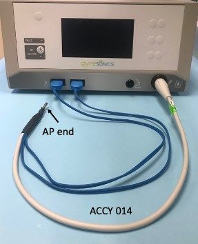
Symbols Glossary

                         SYMBOL        EXPLANATORY              STANDARD
   SYMBOL                                                                             STANDARD TITLE
                          TITLE            TEXT                 REFERENCE
                                                                                   Labeling-Medical devices;
                                                                21 CFR
                                                                                   prominence of required label
                       Prescription   Requires a prescription   801.15(c)(1)(i)F
                                                                                   statements.
                       Only           in the United States.
                                                                21 CFR
                                                                                   Labeling-Prescription devices.
                                                                801.109

LS 06311-002US Rev A                                                                                                vi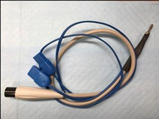
Glossary of Terms, Acronyms, and Definitions

Glossary of Terms, Acronyms, and Definitions
       TERM                                                      DEFINITION
         AP            APPLIED PART: part of ME EQUIPMENT that in NORMAL USE necessarily comes into physical
                       contact with the PATIENT for ME EQUIPMENT or an ME SYSTEM to perform its function. [IEC
                       60601-1 #3.8]
        DUT            Device Under Test which may be either the ESU or the SMART Tablet
     ESU (RFG)         Electrosurgical Unit: Sonata Radiofrequency Generator.
          IA           Leakage current from the applied part. For the ESU (RFG) this consists of leakage from both
                       Handpiece signals and the Neutral electrode connections. For the SMART Tablet this consists of
                       leakage from the Sonata Intrauterine Ultrasound Probe.
          IP           Patient leakage is the current which flows to ground (PE) from the applied parts via the patient.
      IN or IT         Isolated neutral (terre) describes a wiring system where the neutral line connection N is not
                       directly referenced to earth. Electrical Safety tester displays IT at top of display when IT
                       configuration is detected.
          L            Line connection which is typically measures 230 ± 20 VAC to PE in an earth referenced neutral
                       wiring system. (TN)
         LN            Line connection to DUT with normal polarity-L to L and N to N. Leakage currents are measured
                       with both normal and reversed polarity.
        MAP            Mains on APPLIED PART: A method of assessing patient leakage current under the single fault
                       condition where MAINS VOLTAGE is present on the APPLIED PART.
   MAINS PLUG          Part, integral with or intended to be attached to a POWER SUPPLY CORD of electrical
                       equipment, to be inserted into a mains socket-outlet. [IEC 60601-1 #3.50]
        MSO            MULTIPLE SOCKET OUTLET: One or more socket-outlets intended to be connected to, or
                       integral with, flexible cables, cords or ME EQUIPMENT providing SUPPLY MAINS or equivalent
                       voltage. [IEC 60601-1 #3.67]
          N            Neutral line connection which typically measures 0 V ± 15 VAC in an earth referenced neutral
                       wiring system. (TN)
      NE (DE)          Neutral electrode (DE dispersive electrode) provides return path for HF energy from patient to
                       ESU (RFG)
         NL            Line connection to DUT with reversed polarity. DUT N lead measures 230 ± 20 VAC to PE.
         PE            PROTECTIVE EARTH. The PROTECTIVE EARTH CONDUCTOR is a conductor to be
                       connected between the PROTECTIVE EARTH TERMINAL and an external protective earthing
                       system. [IEC 60601-1 #3.93]
        PET            PROTECTIVE EARTH TERMINAL: The PROTECTIVE EARTH TERMINAL is a terminal
                       connected to conductive parts of CLASS I equipment for safety purposes. This terminal is
                       intended to be connected to an external protective earthing system by a PROTECTIVE EARTH
                       CONDUCTOR. [SOURCE: IEC 60601-1:2005, 3.95]
         TN            Terre neutral describes an earth referenced wiring system where the Neutral connection is
                       connected to earth.
        RINS           The insulation resistance includes two resistance measurements. Resistance is measured
                       between shorted mains L and N connections and the PE at the test socket. Resistance is
                       separately measured between the shorted mains L and N connections to the applied part
                       connections.
         RPE           Resistance between protective earth lead and the protective earth terminal in the ESU (RFG)

LS 06311-002US Rev A                                                                                                       vii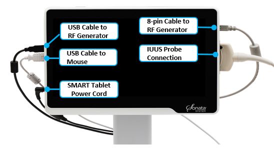
Glossary of Terms, Acronyms, and Definitions

                                      GENERAL WARNINGS AND CAUTIONS

             REFER TO SONATA SYSTEM INSTRUCTIONS FOR USE FOR COMPLETE WARNINGS AND
             CAUTIONS

             COMPONENTS ARE NOT OPERATOR SERVICEABLE
             Do not attempt to remove protective covers on any components of the Sonata System. Parts within the
             protective covers of any component are not serviceable by the operator.

             DO NOT REMOVE COVERS
             DO NOT attempt to remove protective covers on any components of the Sonata System. None of the parts
             within the protective covers of any component are operator serviceable. As outlined in Technical Manual
             Chapter 1, operator serviceable parts may be accessed without removal of the protective covers. The
             protective covers prevent access to potential electrical and mechanical hazards. Touching any components
             behind access covers may create a pathway for current leakage, presenting an electrical shock hazard to
             the operator or to the patient. If the system function is in question, call a Gynesonics representative for
             service

             USE GROUNDED CONNECTIONS
             Use only grounded electrical connections. Connecting the Sonata System to a power source that is not
             equipped with a protective earth contact creates a shock hazard for the operator or may compromise the
             reliability of the system and other equipment attached to the same circuit. Interrupting the protective
             conductor inside or outside the device, or interrupting the protective earth terminal can, create a shock
             hazard for the operator. To achieve the enhanced grounding reliability of the hospital-grade plug provided,
             use an outlet marked “hospital only” or “hospital grade”, if available.

             SALE AND USE
             Federal law restricts this device to sale by or on the order of a physician.

             POWER CORDS AND EXTENSION CORDS
             Use only approved line cords provided by Gynesonics. DO NOT use additional multiple portable socket-
             outlet strips or extension cords

             SMART TABLET CANNOT BE USED AS COMPUTER.
             The SMART Tablet resembles a tablet computer, but DO NOT attempt to use it as one. Actions to use it as
             a tablet computer may damage the system and expose it to risks such as attacks by viruses. These actions
             include installing or updating software, connecting the system to a network, or attempting to access the
             native operating system

            COMPONENT OPENINGS
            DO NOT obstruct any openings on Sonata System components, such as cooling vents for the SMART Tablet
            and for the RF Generator. Doing so may result in compromised product life or cause overheating of
            equipment

             BATTERY
             DO NOT attempt to remove or use the battery inside the SMART Tablet.

LS 06311-002US Rev A                                                                                                       viii
Glossary of Terms, Acronyms, and Definitions
GENERAL WARNINGS AND CAUTIONS
FLUID INGRESS
The SMART Tablet is not protected from fluid spills. The RF Generator is not protected against excess fluid
ingress. Always disconnect cables before cleaning. DO NOT spray cleaners directly into vents, sockets, or
other openings. Fluid ingress may cause device malfunction.
UNPLUG MAIN POWER TO CHECK CONNECTIONS
For optimum safety, unplug the main system power cord before attempting to check power cord connections
to system.
SYSTEM INPUTS AND OUTPUTS
The Sonata System has input/output (I/O) ports that are only intended for particular functions with regards to
external I/O. Patient ablation data records and images may be accessed by connecting a standard USB
drive to the SMART Tablet when the system is not being used for targeting or treatment. A video output
cable may be attached to the Tablet monitor port for a supplemental signal to an external monitor. Beyond
these two (2) ports, no other ports should be used externally for other functions. Attempting to attach any
other form of external I/O may result in a system malfunction or damage.
LS 06311-002US Rev A ixChapter 1: Introduction
Chapter 1 Introduction
1.1 Manufacturer
Gynesonics, Inc.
600 Chesapeake Drive
Redwood City, CA 94063 USA
Telephone: +1 650-216-3860
Fax: +1 650-299-1566
UScustomerservice@gynesonics.com
www.gynesonics.com
1.2 Device Intended Use
The Sonata® Transcervical Fibroid Ablation System 2.1 and 2.2 are intended for diagnostic
intrauterine imaging and transcervical treatment of symptomatic uterine fibroids, including those
associated with heavy menstrual bleeding.
1.3 Room Requirements
The Sonata System is intended for use in locations in which minimally invasive procedures are
performed. The Sonata System is suitable for use within the patient environment as defined by IEC
60601-1. Additional room requirements are defined in the Sonata System Instructions for Use.
• Power: AC 100-240V, 50/60 Hz, 15A max, grounded. Backup is recommended.
• Temperature: 10°C to 35°C for all equipment and components.
• External Monitors: The SMART Tablet may be connected to an external monitor through a
video cable and adapter. The output format is micro HDMI. An adapter from Micro HDMI to
HDMI is provided.
LS 06311-002US Rev A 10Chapter 1: Introduction
1.4 System Overview
The Sonata System is comprised of durable medical equipment, software, and various single-use and
reusable instruments. A Radiofrequency Ablation (RFA) Handpiece attaches to an Intrauterine
Ultrasound (IUUS) Probe to provide sonography-guided RF ablation. Once connected, the assembly of
the RFA Handpiece and the IUUS Probe is referred to as the Treatment Device. The Sonata Graphical
Guidance Software (GGS) integrates ablation planning, targeting, and ablation of fibroids. The SMART
Guide displays a real-time graphic overlay on the live ultrasound image for targeting and
deployment of radiofrequency ablation. The system enables a clinician to deliver radiofrequency
energy to fibroid tissue resulting in thermal fixation and coagulative necrosis of the tissue.
Electrical Overview:
Electrical input ratings (V~, Hz, VA): 100-240 VAC, 50-60 Hz, < 15 A
Electrical classification: Class I
Mode of operation: Suitable for continuous operation
Applied Part (patient lead): Type BF
Figure 1-1. System Block Diagram
LS 06311-002US Rev A 11Chapter 1: Introduction
Figure 1-2. Connection ports on the SMART Tablet.
RF ON/OFF
Power Volume
Switch Control Knob
Potential
Equalization
Conductor Terminal
Power Cord
Footswitch
Figure 1-3. Connections and Controls on the RF Generator.
CAUTIONS
POWER CORDS AND EXTENSION CORDS
Use only approved line cords provided by Gynesonics. DO NOT use additional multiple
portable socket-outlet strips or extension cords
LS 06311-002US Rev A 12Chapter 1: Introduction
1.5 Standards
The Sonata System has been tested to the following standards:
• EN/IEC 60601-1, Medical Electrical Equipment: General Requirements for Safety and
Essential Performance.
• EN/IEC 60601-1-2, Medical Electrical Equipment: General requirements for basic safety and
essential performance – Collateral standard: Electromagnetic compatibility – requirements
and tests.
• EN/IEC 60601-1-6, Medical electrical equipment Part 1-6: General requirements for basic
safety and essential performance - Collateral standard: Usability
• EN/IEC 60601-1-8, Medical electrical equipment Part 1-8: General requirements for basic
safety and essential performance - Collateral standard: General requirements, tests and
guidance for alarm systems in medical electrical equipment and medical electrical systems.
• EN/IEC 60601-2-2, Medical Electrical Equipment: Particular requirements for the basic safety
and essential performance of high frequency surgical equipment and high frequency surgical
accessories.
• EN/IEC 60601-2-37, Medical Electrical Equipment: Particular requirements for the basic
safety and essential performance of ultrasonic medical diagnostic and monitoring
equipment.
The Sonata System components are not anticipated to degrade in performance under normal use
within the expected use life of 5 years. As such, periodic maintenance inspections are not
mandatory. For provider facilities with Quality Assurance Programs that may require routine
inspections the following standards and guidance are recommended for service tests:
• NFPA® 99 Health Care Facilities Code
• NFPA 99 Health Care Facilities Code Handbook
• IEC 62353 Recurrent test and test after repair of medical electrical equipment
• ANSI/AAMI ES 60601-1; EN 60601-1
LS 06311-002US Rev A 13Chapter 1: Introduction
1.6 Reference Documents
The Sonata System 2.1 and 2.2 Instructions for Use with Technical Appendix describe:
• Intended use, patient selection, and risks;
• Room requirements, system setup, and accessories;
• Sonata System description and procedure, including user control Interface and messages
• Troubleshooting
• Clinical trial results
• Technical information
Additional copies of the Sonata System Instructions for Use with Technical Appendix may be obtained from
Gynesonics.
Table 1 Sonata System 2.1 and 2.2 Instructions for Use (IFU) with Technical Appendix
Sonata System Sonata System
Durable Equipment Software IFU Order #
Sonata System 2.1: REF-005
SONATA2-110 SW-002 Sonata System 2.2: REF-009
1.7 Personnel Qualification and Service Documentation
The procedures in this manual are intended to be performed by personnel who are trained in the
maintenance of electrical equipment, such as typically found in hospital biomedical engineering
departments. Personnel should review and understand this manual thoroughly prior to performing
procedures described herein. Supplemental training is available from Gynesonics upon request. For
all other service, contact Gynesonics or an authorized distributor.
All service information and data should be recorded on the FRM 06311-004 Sonata System Service
Form: Basic Safety and Function Checks. An updated safety check label should be added to the
system cart with date and service signature.
CAUTION
Procedures in this manual are intended to be performed by personnel who are trained
in the maintenance of electrical equipment. Electrical testing may present shock risk to
the testing personnel and if performed improperly may lead to reduced safety or loss of
function.
LS 06311-002US Rev A 14Chapter 1: Introduction
1.8 Tools Recommended for Service
Various measurement instruments for Medical Electronic (ME) Equipment devices may be used to
perform these tests. The instruments should conform to one or more of the requirements in the
standards outlined in Section 1.5.
Examples of appropriate instruments include:
• DALE 601 Electrical Safety Analyzer
• Fluke ESA620/615/614/612 Electrical Safety Analyzer
The following connective tools are necessary for the testing and can be obtained from Gynesonics.
• ACCY-014 Patient Lead Grounding Cable
Used for measurement of Patient Lead leakage current
Figure 1-4. ACCY-014 Patient Lead Grounding Cable
LS 06311-002US Rev A 15Chapter 2: Electrical Safety Tests
Chapter 2 Electrical Safety Tests
The electrical safety tests in this section are based on and conform to IEC 62353 and NFPA 991. They
are intended for electrical safety evaluation of cord-connected, electrically operated, patient care
equipment. If additional information is needed, refer to IEC 62353 and NFPA 99 or the
corresponding Handbook.
The tests summarized in Table 2 should be performed at regular intervals. The suggested interval is
annual or consistent with user site policy.
All tests listed in Table 2 can be done with a Safety Analyzer listed in 1.8 or equivalent.
To connect to the Safety Analyzer, use ACCY-014 Patient Lead Grounding Cable.
To connect to the chassis for leakage tests, connect to the Potential Equalization post on the chassis.
Table 2 Routine Electrical Safety Tests
Instructions
Testing Item and Test Standards Clause Acceptance Criteria
Conditions
Any condition that appears to affect
proper operation or present an
otherwise unsafe condition should
IEC 62353: Clause 5.2 be repaired or replaced.
Visual Inspection of
§2.1 NFPA 99:2018 Safety related markings and labels
Physical Integrity
10.3.1 should be legible and complete
Sonata System documentation is
available and reflects the current
configuration of the system
IEC 62353: Clause 5.3.2.2b
Ground Resistance ≤ 0.30 Ω (IEC 62353)
§2.2 NFPA 99:2018
(PE to Ground) ≤ 0.50 Ω (NFPA 99)
10.3.2
Insulation Resistance
§2.2 IEC 62353: Clause 5.3.3 ≥2MΩ
(Mains to PE)
Earth Leakage Current
§2.3 IEC 60101-1 subclause 8.7.3 ≤ 500 A
(LN)
Earth Leakage Current
§2.3 IEC 60101-1 subclause 8.7.3 ≤ 500 A
(NL)
Touch (Chassis) Current, IEC 62353: Clause 5.3.4.1
§2.3 ≤ 500 μA
NFPA 99:201810.3.3, 10.3.5
Patient Lead Leakage, NFPA 99:2018
§2.4 ≤ 100 µA
Ground switch CLOSED 10.3.6
Patient Lead Leakage, §2.4 IEC 62353: Clause 5.3.4.3 ≤ 500 µA
1 IEC 62353, ED 2.0:2014; NFPS® 99 Health Care Facilities Code Eleventh Edition 2018, §10.3
LS 06311-002US Rev A 16Chapter 2: Electrical Safety Tests
Ground switch NFPA 99:2018
OPEN 10.3.6
The minimum and maximum of
all 4 temperature channel read
Functional Test §2.5 EN 62353 #5.4
by the RF Generator are within
4°C.
CAUTION
Electric Shock Hazard. When the meter's ground switch is OPEN, don't touch the unit!
2.1 Visual Inspections
Visual inspections form a critical part of the general safety inspections during the functional life of
the product. Confirm the physical integrity of the power cord assembly and other Sonata System
components as listed in Table 3.
Table 3 Visual Inspection
SPECIFICATION INSPECTION
System Safety Marking and Labeling Labels are intact and legible
Check for any obstructions on Cart wheels,
Physical integrity
wheel locks, and handles.
No external damages or cracks on housing and
Housing and Enclosure
enclosure of the RF Generator and Tablet.
Cabling, including power cords, USB and
Look for defects such as cuts and wear.
Sync cables
User documentation or IFU The documentation is accessible and up to date
Replace cords if the attachment plug blades are bent. DO NOT re-straighten and DO NOT attempt to
repair abnormal cables. If damage has occurred to the insulation, replace the cord or cable
immediately, as electric shock and/or equipment damage may result.
Any condition that appears to affect proper operation or present an otherwise unsafe condition
should be repaired or replaced. For replacement of cords, connectors, or accompanying
documentation, contact the Gynesonics Representative.
2.2 Insulation Resistance
Measure resistance between the chassis and the ground pin of the attachment plug as shown in
Figure 1-1 through 2-3. During test, the cord shall be flexed at its connection to the attachment plug
or connector, and at its connection to the strain relief on the chassis. Note that vigorous flexing is
not needed.
LS 06311-002US Rev A 17Chapter 2: Electrical Safety Tests
Figure 1-1. Connections for the Ground Resistance Test
Figure 2-2. The measurement of the Ground Resistance (Ref IEC 62353 Figure 1)
Figure 2-3. The measurement of the insulation resistance (Ref IEC 62353 Figure 3)
LS 06311-002US Rev A 18Chapter 2: Electrical Safety Tests
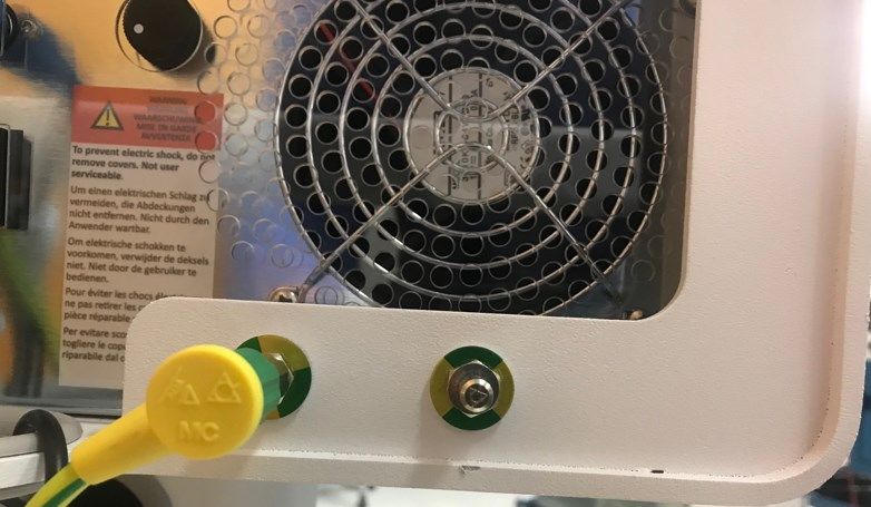
2.3 Earth Leakage and Touch Current
Earth Leakage Current is defined in IEC 60101-1 subclause 8.7.3. Measure Earth Leakage Current as
shown in Figure 2-4.
Figure 2-4 The measurement of earth leakage current (Open the “APPIED PART” switch)
Ensure that Resistance has been tested per §2.2 and Earth Leakages are also tested and meet
acceptance criteria prior to testing touch current. Personnel safety may be compromised if the
grounding conductor is not intact and the leakage (or touch) current is high.
Measure touch current as described below. Conditions of test include:
• Normal polarity
• Ground wire disconnected (SFC)
The cart is the only conductive surface accessible to the operator or patient when in normal use
position. Therefore, the touch leakage current is measured between the PE post located on the rear
of the cart and Grounding contact as shown in Figure 2-5.
LS 06311-002US Rev A 19Chapter 2: Electrical Safety Tests
PE Post for
Leakage Tests
Figure 2-5. Touch Current Test Connections
LS 06311-002US Rev A 20Chapter 2: Electrical Safety Tests
2.4 Patient Lead Leakage
Measure patient lead leakage using Patient Lead Grounding Cable ACCY-014. Conditions of test
include:
• Power plug connected normally
• System powered on
• Ground switch CLOSED (NC limit ≤ 100 μA), and separately with
ground switch OPEN (SFC limit ≤ 500 μA)
• Leakage current measured between all patient leads (RFA Handpiece and Dispersive
Electrodes) connected together and ground
Figure 2-5. Patient Lead Leakage Test Connection
LS 06311-002US Rev A 21Chapter 2: Electrical Safety Tests
2.5 Temperature Sensing Accuracy Check
1. Sonata System is designed with built-in self-calibration and safety check functions. No
manual calibration is needed during the regular service.
2. Sonata System RF energy delivery is controlled to reach and maintain tissue temperature of
105 °C as measured by thermocouples in the Radiofrequency Ablation (RFA) Handpiece.
3. Temperature variation (variation between signal to signal when measuring the same
reference medium) is the primary test of temperature sensing accuracy. The test below
evaluates the accuracy of the Sonata RF Generator to read all thermocouples of each
handpiece which was calibrated at Gynesonics manufacture.
Figure 2-6. Open the Audit Trail File in the system configuration
Figure 2-7. Check the thermocouple readings
LS 06311-002US Rev A 22Chapter 2: Electrical Safety Tests
Table 4. Recommended Temperature Sensing Test:
TITLE NOMINAL PASS LIMIT CHECK INSTRUCTION
TEST VALUE
Thermocouple Site Room The minimum Click the message column to sort data and scroll
Check Ambient and maximum of down to find “Hand Piece Connected TC’s” (Figure
all 4 temperature 2.7). If the maximum and minimum of the 4
channels read by temperature values are within a 4°C range, the
the RF Generator test is passing.
are within 4°C.
If the difference of maximum and minimum values is larger 4°C, contact Gynesonics for replacement RF
Generator unit.
LS 06311-002US Rev A 23Chapter 3: Troubleshooting Chapter 3 Troubleshooting Sonata System provide comprehensive messages for the system and device errors. Please refer the error code list in Chapter 7 of the Sonata System Instructions for Use. Anytime an abnormal condition is identified, contact Gynesonics Service. LS 06311-002US Rev A 24
Chapter 4: Field Replacement and
                                                                                 Software Upgrade

Chapter 4 Field Replacement and
          Software Upgrade

                                              WARNING

            The Sonata System 2.2 is NOT designed to be field repairable. Do not attempt to service
            any defective components in field as doing so may compromise function, risk, or safety.
            Contact Gynesonics Service if any component needs to be replaced.

The Sonata System 2.1 or Sonata System 2.2 hardware upgrade should be performed by a
Gynesonics service representative. After the upgrade, the system visual inspections and safety tests
should be performed and documented per this procedure.

Manufacturer initiated periodic software updates may be required and can be performed by a
Gynesonics service representative.

All service information and data should be recorded on the FRM 06311-004 Sonata System Service
Form: Basic Safety and Function Checks. A safety check label should be added to the system cart
with date and service signature.

LS 06311-002US Rev A                                                                                  25
600 Chesapeake Drive
Redwood City, CA 94063 USA
Telephone: +1-650-216-3860
Fax: +1 650-299-1566
www.gynesonics.com
UScustomerservice@gynesonics.com
The Sonata System 2.2 is intended for diagnostic intrauterine imaging and transcervical treatment of symptomatic uterine
fibroids, including those associated with heavy menstrual bleeding. To learn more, visit www.gynesonics.com/sonata-system.
Gynesonics, Sonata, and the logo are trademarks and registered trademarks of Gynesonics, Inc. All other trademarks are
properties of their respective owners. Gynesonics products are covered by US and foreign patents. See
www.gynesonics.com/patents. ©2021 Gynesonics, Inc.
Manual Catalog # REF-011US. LS 06311-002US. Rev A January 2021You can also read