Bottom Fill Bore Pumps - INSTALLATION & OPERATIONS MANUAL - Airwell Group
←
→
Page content transcription
If your browser does not render page correctly, please read the page content below
Bottom Fill Bore Pumps
INSTALLATION & OPERATIONS MANUAL

AIRWELL GROUP PTY LTD | 30 Harris Rd, Malaga WA 6090 | P: +61 8 9209 2666 | www.airwellgroup.com.au
DESIGNED AND MANUFACTURED IN AUSTRALIA

                                    A.B.N. 46 009 323 871
                       30 Harris Road, Malaga, Western Australia 6090
                       Tel: (61) 08 9209 3355 - Fax: (61) 08 9209 2666
                              Email: sales@airwellgroup.com.au
                              http://www.airwellgroup.com.au

            Read this manual

            Carefully read this manual before commissioning or servicing the product.

            Notes:
            - This documentation is part of the product.
            - Retain the documentation during the entire service life of the product.
            - Pass on the documentation to any subsequent user.
            - Ensure that any supplement to this documentation is included, if necessary.

The contents and specifications herein are subject to change without notice. All rights reserved.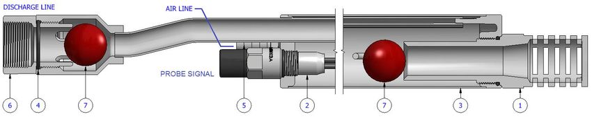
Airwell Group Pty Ltd | Bottom fill bore pumps

             1         INTRODUCTION..............................................................................................................................3
                       1.1 How the airwell pump works ............................................................................................... 3
             2         BOTTOM FILL PUMPS RANGE.........................................................................................................4
                       2.1 Bottom fill pumps 1.75” with reed switch (BF175 . . ) .......................................................... 5
                       2.2 Bottom fill pumps 1.75” with probes (BF175 . . P) ............................................................... 6
                       2.3 Bottom fill pumps 2” (BF20 . . ) ............................................................................................ 7
                       2.4 Bottom fill pumps 3” (BF30 . . ) ............................................................................................ 8
                       2.5 Bottom fill pumps 3.5” (BF35 . . ) ......................................................................................... 9
                       2.6 Bottom fill pumps 4” (BF40 . . ) .......................................................................................... 10
                       2.7 Bottom fill pumps 6” (BF60 . . ) .......................................................................................... 11
                       2.8 Bottom fill pumps 8” (BF80 . . ) .......................................................................................... 12
             3         FITTING KITS ................................................................................................................................13
             4         PUMPS SPECIFICATIONS ..............................................................................................................14
             5         SAFETY .........................................................................................................................................15
             6         TOOLS REQUIRED FOR THIS JOB...................................................................................................16
             7         PUMP ASSEMBLY .........................................................................................................................17
                       7.1 Airline connection .............................................................................................................. 17
                       7.2 Water riser connection ...................................................................................................... 19
                       7.3 Cable kit connection........................................................................................................... 19
                       7.4 Wire rope connection ........................................................................................................ 20
                       7.5 Getting the pump ready ..................................................................................................... 20
             8         LOWERING THE PUMP DOWNHOLE .............................................................................................21
                       8.1 Pumps with poly risers ....................................................................................................... 21
                       8.2 Pumps with stainless steel risers........................................................................................ 22
             9         CORROSION FACTORS ..................................................................................................................26
             10        MAINTENANCE ............................................................................................................................27
                       10.1 Regular checks ................................................................................................................. 27
                       10.2 Purging the pump – Method A ......................................................................................... 27
                       10.3 Purging the pump – Method B ......................................................................................... 28
                       10.4 Depressurising the system ............................................................................................... 28
                       10.5 Removal of pump from bore and service. ........................................................................ 28
                       10.6 Cleaning the probes ......................................................................................................... 28
             11        TORQUE SETTINGS .......................................................................................................................30
             12        WARRANTY DETAILS ....................................................................................................................31
             13        WARRANTY REGISTRATION CARD................................................................................................32

                                                 pumping solutions for all applications | www.airwellgroup.com.au
                       MAN_5502                  Revision: 15.0        Status: Approved          Issue Date: 15/07/2020               Page 2 of 33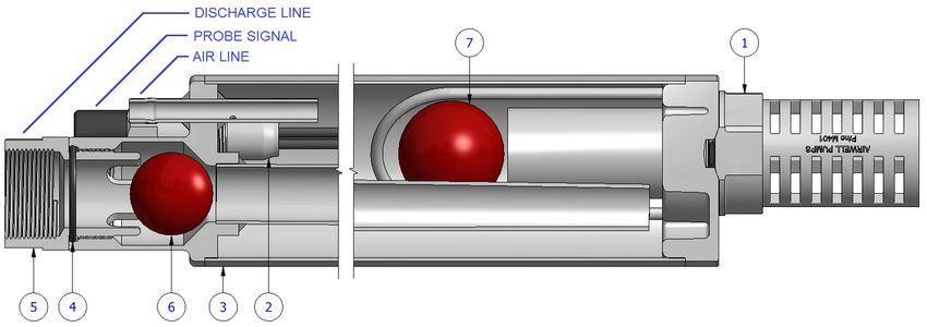
Airwell Group Pty Ltd | Bottom fill bore pumps

  1     INTRODUCTION

  This manual covers the operation, maintenance, servicing and troubleshooting of the Airwell bottom fill bore
  pumps. Although these pumps can be found in different formats and sizes, their basic principles are in common.

  1.1 How the airwell pump works

  Compressed air is a particularly useful means of transferring energy to pump water. Air compressed at an existing
  power source can be carried significant distances through MDPE polyethylene pipe with limited loss of pressure,
  saving a costly power installation to the water source, whilst allowing the compressor to be used for multiple
  pumps, or other local purposes.

  The Airwell pump component is a 316L grade stainless steel tube that can be manufactured in varying forms and
  sizes to suit a variety of different applications. The tube is enclosed at each end and incorporates a foot valve(s) to
  allow the submerged vessel to fill with water and a check valve on the outlet preventing the return of the
  expelled water. The valves are our own design and incorporate special features to provide exceptional ability to
  handle silt and sand, whilst keeping a very simple, maintenance free construction. The clean, hard valve seats
  provided for the polyurethane balls to close on are kept clean by the circulation of the water and are raised above
  the bottom of the pump to minimise contamination.

  Within our most popular pumps there are two level (conductivity) probes; one long enough to reach the bottom
  of the pump to detect when the pump is empty, and one short one to detect when it’s full. This is the key to the
  automatic function of the pump. We use the conductivity of water to monitor the high and low fluid levels in the
  pump. This means that a ‘contact’ is made when the water rises to the height of the short probe at the top of the
  vessel, (now both probes are wet) and is ‘broken’ when the water level falls below the lower probe at the bottom
  of the pump, (when both probes are dry).

  An electronic circuit in the control unit detects this making and breaking of water contact, and subsequently
  changes the state of a 3-way solenoid valve, allowing compressed air to the pump when a ‘full’ signal is received,
  forcing the water up the discharge pipe, and then exhausting the air pressure to allow the pump to refill when the
  ‘empty’ signal is seen. The result of this is that the Airwell Pump will only cycle when a 'full' or 'empty' signal is
  received, regardless of this being every few seconds, minutes, hours, weeks or years.

  The control unit is located close to the pump, but above water level. Besides carrying the 3-way valve for the air
  and the electronic control circuit, it also houses a 4.5 Amp/hour dry cell battery to power the system, which in
  turn is recharged by the solar panel on the lid of the controller. Mains powered systems are available for those
  applications where power is close to the water source, as are multiple pump controllers, flow monitoring and flow
  control options.

  It should be noted that the solenoid valve is a ‘latching’ type valve and requires a short pulse of power (60
  milliseconds) in one direction to change state and will stay that way until a pulse in the opposite direction
  changes it. A conventional solenoid requires permanent energisation to maintain either an open or closed state.

  Should power be lost to the microprocessor, upon reconnection, the system will initialise on pressure, expelling
  any water in the pump, and regaining a reference for the controller. The water delivered by an Airwell system
  comes in surges, not a continuous flow like that of most electric pumps. Flow rates from the Airwell pump vary
  dependant on many factors.

                                                 pumping solutions for all applications | www.airwellgroup.com.au
                       MAN_5502                  Revision: 15.0      Status: Approved        Issue Date: 15/07/2020   Page 3 of 33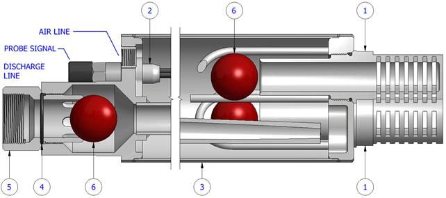
Airwell Group Pty Ltd | Bottom fill bore pumps

  2     BOTTOM FILL PUMPS RANGE

                                                 pumping solutions for all applications | www.airwellgroup.com.au
                       MAN_5502                  Revision: 15.0      Status: Approved        Issue Date: 15/07/2020   Page 4 of 33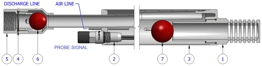
Airwell Group Pty Ltd | Bottom fill bore pumps
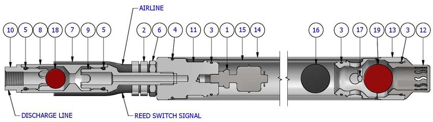
2.1 Bottom fill pumps 1.75” with reed switch (BF175 . . )
Item Qty Type Description
BF17510 BF17520
1 1 E065 Float reed switch
2 4 H013A O-clip 9-11mm (316 S/S)
3 3 H035 O-ring BS026 (Nitrile N70)
4 2 H038 O-ring BS029 (Nitrile N70)
5 2 H078 O-ring BS118 (Nitrile N70)
6 2 H213S Tailpiece (316 S/S) ¼” hose x ¼” BSPT
7 2 H252 Nylon tube Ø3/8” x Ø9/32”
8 1 M502 Ball valve
9 1 M503 Castle stand
10 1 M504 Castle bush
11 1 M505 Top end cap
12 1 M507 Bottom inlet screen
13 1 M508 Bottom end cap
14 1 M519 M517 Outer body
15 1 M520 M518 Inner body
16 1 NU030 Floating ball Ø30 (Nitrile N70)
17 1 RM005A Bar (316 S/S) Ø3/16”
18 1 U024 Urethane ball Ø24
19 1 U030 Urethane ball Ø30
pumping solutions for all applications | www.airwellgroup.com.au
MAN_5502 Revision: 15.0 Status: Approved Issue Date: 15/07/2020 Page 5 of 33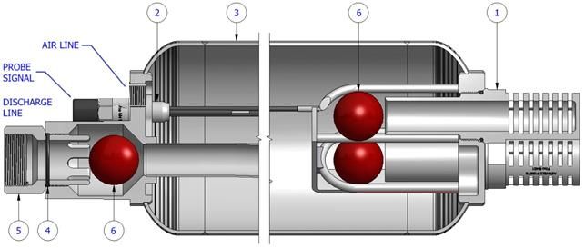
Airwell Group Pty Ltd | Bottom fill bore pumps
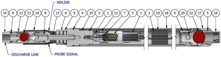
2.2 Bottom fill pumps 1.75” with probes (BF175 . . P)
Item Qty Type Description
BF17510P BF17520P
1 1 A090 A091 Probe holder assembly
2 1 FA0213 Probe holder adaptor
3 1 GA0046 Gland plug bottom assembly
4 4 H013A O-clip 9-11mm (316 S/S)
5 3 H035 O-ring BS026 (Nitrile N70)
6 2 H038 O-ring BS029 (Nitrile N70)
7 2 H047 O-ring BS016 (Nitrile N70)
8 2 H078 O-ring BS118 (Nitrile N70)
9 2 H213S Tailpiece (316 S/S) ¼” hose x ¼” BSPT
10 2 H252 Nylon tube Ø3/8” x Ø9/32”
11 1 M238 Knurled nut – Pump fixing
12 1 M502 Ball valve
13 1 M503 Castle stand
14 1 M504 Castle bush
15 1 M505 Top end cap
16 1 M507 Bottom inlet screen
17 1 M508 Bottom end cap
18 1 M519 M517 Outer body
19 1 M520 M518 Inner body
20 1 RM005A Bar (316 S/S) Ø3/16”
21 1 U024 Urethane ball Ø24
22 1 U030 Urethane ball Ø30
pumping solutions for all applications | www.airwellgroup.com.au
MAN_5502 Revision: 15.0 Status: Approved Issue Date: 15/07/2020 Page 6 of 33
Airwell Group Pty Ltd | Bottom fill bore pumps

2.3 Bottom fill pumps 2” (BF20 . . )

                       Item       Qty                              Type                                    Description

                                            BF2005            BF2010            BF2020
                           1          1     FA0081            FA0014           FA0015        Pump body
                           2          1                        M247                          Ball seat and inlet screen
                           3          1                        M027                          Castle bush
                           4          2                        H078                          O-ring BS119 (Nitrile N70)
                           5          1     GA0032            GA0033           GA0034        Probe holder
                           6          1                        H212S                         Tailpiece (S/S) Ø1/4” x 1/8”BSPT
                           7          2                        U024                          Urethane ball Ø24

                                                  pumping solutions for all applications | www.airwellgroup.com.au
                        MAN_5502                  Revision: 15.0          Status: Approved    Issue Date: 15/07/2020     Page 7 of 33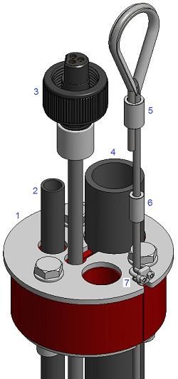
Airwell Group Pty Ltd | Bottom fill bore pumps

  2.4 Bottom fill pumps 3” (BF30 . . )

                      Item       Qty                              Type                                    Description

                                           BF3010            BF3015            BF3020
                          1        1                          A032S                         Inlet screen
                          2        1       GA0035            GA0036           GA0019        Probe holder
                          3        1       FA0016            FA0077           FA0018        Pump body
                          4        1                          H050                          O-ring BS224 (Nitrile N70)
                          5        1                          H210S                         Tailpiece (S/S) Ø1/2” x 3/8”BSPT
                          6        1                          M026                          Castle bush
                          7        2                          U044                          Urethane ball Ø44

                                                 pumping solutions for all applications | www.airwellgroup.com.au
                       MAN_5502                  Revision: 15.0          Status: Approved    Issue Date: 15/07/2020     Page 8 of 33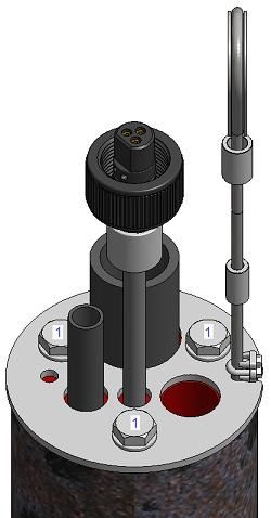
Airwell Group Pty Ltd | Bottom fill bore pumps

  2.5 Bottom fill pumps 3.5” (BF35 . . )

     Item      Qty                                                  Type                                                      Description

                        BF3505         BF35075             BF3510       BF3520          BF3530        BF3560
         1         1                                             A033S                                                Inlet screen
         2         1 GA0037            GA0038              GA0021 GA0022                GA0039        GA0040          Probe holder
         3         1 FA0039            FA0040              FA0019 FA0020                FA0021        FA0041          Pump body
         4         1                                             H050                                                 O-ring BS224 (Nitrile N70)
         5         1                                             M026                                                 Castle bush
         6         1                                             U044                                                 Urethane ball Ø44
         7         1                                             U056                                                 Urethane ball Ø56

                                                 pumping solutions for all applications | www.airwellgroup.com.au
                       MAN_5502                  Revision: 15.0      Status: Approved        Issue Date: 15/07/2020         Page 9 of 33
Airwell Group Pty Ltd | Bottom fill bore pumps
2.6 Bottom fill pumps 4” (BF40 . . )
Item Qty Type Description
BF4005 BF40075 BF4010 BF4015 BF4020 BF4030 BF4060
1 1 A033S Inlet screen
2 1 GA0037 GA0038 GA0021 GA0025 GA0022 GA0039 GA0040 Probe holder
3 1 FA0022 FA0023 FA0024 FA0025 FA0026 FA0027 FA0028 Pump body
4 1 H050 O-ring BS224 (Nitrile N70)
5 1 M026 Castle bush
6 1 U044 Urethane ball Ø44
7 1 U056 Urethane ball Ø56
pumping solutions for all applications | www.airwellgroup.com.au
MAN_5502 Revision: 15.0 Status: Approved Issue Date: 15/07/2020 Page 10 of 33Airwell Group Pty Ltd | Bottom fill bore pumps
2.7 Bottom fill pumps 6” (BF60 . . )
Item Qty Type Description
BF6010 BF6020 BF6030
1 2 A033S Inlet screen
2 1 GA0021 GA0022 GA0039 Probe holder
3 1 FA0029 FA0030 FA0031 Pump body
4 1 H059 O-ring BS227 (Nitrile N70)
5 1 M029 Castle bush
6 3 U056 Urethane ball Ø56
pumping solutions for all applications | www.airwellgroup.com.au
MAN_5502 Revision: 15.0 Status: Approved Issue Date: 15/07/2020 Page 11 of 33Airwell Group Pty Ltd | Bottom fill bore pumps
2.8 Bottom fill pumps 8” (BF80 . . )
Item Qty Type Description
BF8005 BF8010 BF8015
1 2 A033S Inlet screen
2 1 GA0042 GA0043 GA0029 Probe holder
3 1 FA0120 FA0118 FA0042 Pump body
4 1 H059 O-ring BS227 (Nitrile N70)
5 1 M029 Castle bush
6 3 U056 Urethane ball Ø56
pumping solutions for all applications | www.airwellgroup.com.au
MAN_5502 Revision: 15.0 Status: Approved Issue Date: 15/07/2020 Page 12 of 33Airwell Group Pty Ltd | Bottom fill bore pumps
3 FITTING KITS
The pump fitting kit is packed inside a plastic bag and in generally
contains:
1. A tape for taping hoses together.
2. A grip for the wire rope.
3. A D-shackle for hanging the pump on the wire rope. A second
D-shackle to anchor the wire rope outside the bore casing.
4. Clamp or nut for the airline hose, depending on the pump size.
The airline fitting kit contains:
1. End connector to connect the main compressor airline to the
controller.
2. End connector to connect the pump airline to the controller.
The water riser fitting kit contains:
1. Elbow to connect onto pump discharge riser at bore head.
2. End connector to connect the discharge riser to the discharge
line.
pumping solutions for all applications | www.airwellgroup.com.au
MAN_5502 Revision: 15.0 Status: Approved Issue Date: 15/07/2020 Page 13 of 33Airwell Group Pty Ltd | Bottom fill bore pumps
4 PUMPS SPECIFICATIONS
Pump type Diameter Nominal Actual Weight Displacement Discharge
length length line thread
(inch) (mm) (m) (mm) (kg) (Lit) (BSP)
BF17510 1+3/4” Ø45 1 1222 4.6 0.8 1/2"
BF17510P 1+3/4” Ø45 1 1222 5.0 0.7 1/2"
BF17520 1+3/4” Ø45 2 2221 7.8 1.8 1/2"
BF17520P 1+3/4” Ø45 2 2221 8.2 1.7 1/2"
BF2005 2” Ø51 0.5 822 2.9 0.6 1/2"
BF2010 2” Ø51 1 1322 4.4 1.3 1/2"
BF2020 2” Ø51 2 2322 7.6 2.8 1/2"
BF3010 3” Ø77 1 1399 8.1 2.6 1+1/2"
BF3015 3” Ø77 1.5 1899 10.3 4.4 1+1/2"
BF3020 3” Ø77 2.0 2399 12.6 6.2 1+1/2"
BF3505 3+1/2” Ø89 0.5 876 6.6 1.3 1+1/2"
BF35075 3+1/2” Ø89 0.75 1126 7.8 2.2 1+1/2"
BF3510 3+1/2” Ø89 1 1376 9.7 3.4 1+1/2"
BF3520 3+1/2” Ø89 2 2376 14.8 8.3 1+1/2"
BF3530 3+1/2” Ø89 3 3376 20.0 13.2 1+1/2"
BF3560 3+1/2” Ø89 6 6376 36.1 27.8 1+1/2"
BF4005 4” Ø102 0.5 730 7.6 1.8 1+1/2"
BF40075 4” Ø102 0.75 980 9.0 3.1 1+1/2"
BF4010 4” Ø102 1 1230 10.4 4.7 1+1/2"
BF4015 4” Ø102 1.5 1730 13.2 8.1 1+1/2"
BF4020 4” Ø102 2 2230 16.1 11.5 1+1/2"
BF4030 4” Ø102 3 3230 22.0 18.4 1+1/2"
BF4060 4” Ø102 6 6230 39.4 38.6 1+1/2"
BF6010 6” Ø153 1 1280 20.6 11.2 2”
BF6020 6” Ø153 2 2280 30.0 27.5 2”
BF6030 6” Ø153 3 3280 39.6 43.5 2”
BF8005 8” Ø219 0.5 918 26.4 12.0 2”
BF8010 8” Ø219 1 1418 37.5 28.2 2”
BF8015 8” Ø219 1.5 1918 48.5 45.2 2”
pumping solutions for all applications | www.airwellgroup.com.au
MAN_5502 Revision: 15.0 Status: Approved Issue Date: 15/07/2020 Page 14 of 33Airwell Group Pty Ltd | Bottom fill bore pumps
5 SAFETY
Protective equipment required for the jobs described below:
Responsibilities of the person in charge:
- Identify the hazards that arise due to the special working conditions.
- Implement these hazards in the form of operating instructions.
- Specify clearly the responsibilities for the installation, operation, troubleshooting, maintenance and cleaning
of this equipment.
- Ensure all personnel is trained and informed about the dangers at regular intervals.
- Ensure that this equipment is always in technically perfect conditions.
Caution
Access to the equipment is only permitted to qualified persons or persons specially
trained by Airwell Group for this purpose.
Warning
This equipment is designed and constructed exclusively for the proper use described
in this manual.
Misuse of this equipment can cause dangerous situations.
pumping solutions for all applications | www.airwellgroup.com.au
MAN_5502 Revision: 15.0 Status: Approved Issue Date: 15/07/2020 Page 15 of 33Airwell Group Pty Ltd | Bottom fill bore pumps
6 TOOLS REQUIRED FOR THIS JOB
Spanners
or
Adjustable spanners
or
Socket wrench.
A pair of 1” pipe wrenches
A set of screwdrivers
Poly pipe cutter
Loctite 569 or PTFE tape for thread sealing
Grease for S/S threads
pumping solutions for all applications | www.airwellgroup.com.au
MAN_5502 Revision: 15.0 Status: Approved Issue Date: 15/07/2020 Page 16 of 33Airwell Group Pty Ltd | Bottom fill bore pumps
7 PUMP ASSEMBLY
Before starting the assembly, please pay attention to the following:
- You must have arranged the water riser plus the fitting needed to connect it to the pump discharge outlet. For
correct fitting thread size please refer to the “pumps specifications” table above.
- The threads on the poly fittings used for the air and water connections require sealing. Airwell use and
recommends Loctite 569 for this purpose.
- Attach a weight to the s/s cable provided, and lower it into the borehole to determine the correct depth of the
hole. Lay the s/s cable on the ground and use as a measure to determine the air and riser pipe length.
Remember that the cable attaches to the top of the pump.
- Lay the pump down on a clean spot.
Typical Airwell pump connecting points:
1. Airline.
2. Discharge line.
3. Probe signal cable.
4. Lifting lug for S/S wire rope.
7.1 Airline connection
BF175… pumps:
Connect the airline tube to the existing Swagelok fitting as indicated.
Note: Do not confuse with the other Swagelok fitting which is for
the signal cable connection.
BF20…, BF30... pumps:
Slide the two clamps onto the poly pipe.
Push the poly pipe onto the airline inlet barb far enough, ensuring it
has reached the end.
Slide the two clamps well over the barb and crimp them.
pumping solutions for all applications | www.airwellgroup.com.au
MAN_5502 Revision: 15.0 Status: Approved Issue Date: 15/07/2020 Page 17 of 33Airwell Group Pty Ltd | Bottom fill bore pumps
BF35…, BF40…, pumps:
Slide the hex taper nut onto the S/S airline inlet pipe.
Ensure the nut is oriented so that the tapered side of the nut thread
is outward, as shown.
Push the poly pipe onto the airline inlet pipe, ensuring it is well over
the lump in the fitting, as shown.
At the same time start threading the nut onto the poly airline
ensuring the nut starts to thread on to the poly pipe squarely.
Continue to thread the nut onto the poly until the nut starts to find
resistance up against the lump in the pump fitting.
You should also make sure that the poly is pushed onto the fitting far
enough, and you do the nut up enough, so you can at least see poly
protruding out behind the nut face as shown.
BF60…, BF80…, pumps:
Slide the T-bolt clamp onto the poly pipe.
Push the poly pipe onto the airline inlet barb far enough, ensuring it
has reached the end.
Slide the T-bolt clamp well over the barb and tighten it.
pumping solutions for all applications | www.airwellgroup.com.au
MAN_5502 Revision: 15.0 Status: Approved Issue Date: 15/07/2020 Page 18 of 33Airwell Group Pty Ltd | Bottom fill bore pumps
7.2 Water riser connection
Screw the end connector for your water riser into the castle bush at
the top of the pump.
Note: Advise the “specifications” table for the correct sized
thread.
7.3 Cable kit connection
At each end of the cable kit there is a plastic plug. It is important to
ensure the two O-rings fitted into the grooves of the plug with the
stainless-steel nut, are clean and in good condition.
Do not use any sealer on these plugs, although generous amounts of
penetrating oil / water dispersant are recommended to lubricate O-
rings.
Note: If water has entered the cable kit, the pump will not
operate. Contact Airwell for drying and repair instructions.
If you are using a sealing type well cap and the riser is Ø40mm, you
will need to pass the end of the cable with small stainless-steel nut
through the well cap, before you attach it to the pump unit as the
plug on the other end is too large to pass through the hole.
Note that this plug will only plug into the pump one way.
Push the cable kit plug with the stainless-steel nut on the top of the
probe holder, as far as you can into the socket.
Screw the nut, ensuring you don’t use it to drive the plug home, as it
may be inclined to gall the thread.
The nut should only be a bit more than finger tight.
Note: Damage to the O-rings and plastic parts could result from
over tightening.
pumping solutions for all applications | www.airwellgroup.com.au
MAN_5502 Revision: 15.0 Status: Approved Issue Date: 15/07/2020 Page 19 of 33Airwell Group Pty Ltd | Bottom fill bore pumps
7.4 Wire rope connection
Connect the wire rope loop to the pump lifting lug by using the D-
shackle provided.
Note: Only pumps with poly water risers are supported on wire
rope. Pumps with S/S risers are being supported on the risers
only.
7.5 Getting the pump ready
Lay the hoses (air, water, and electrical cable) out ready for taping together.
Start taping at the pump end, being sure to keep all the hoses at an even length, and making sure that the probe
wire is not stretched.
The s/s wire rope line is only taped into the bundle for the first metre, and from there, it is left free.
Wrap at least 6 turns of tape around the hoses about every one metre.
Use plenty of tape just above the pump to prevent wire rope shackles from protruding unnecessarily.
Note: Do not tape over stainless pump as this can be bad for corrosion.
Your pump is now ready to be lowered into the bore.
pumping solutions for all applications | www.airwellgroup.com.au
MAN_5502 Revision: 15.0 Status: Approved Issue Date: 15/07/2020 Page 20 of 33Airwell Group Pty Ltd | Bottom fill bore pumps
8 LOWERING THE PUMP DOWNHOLE
8.1 Pumps with poly risers
It is recommended that a tripod or windlass be used to lower the
pump.
While the pump is still at the surface, have someone to assist you to
raise the water riser pipe up in a loop whilst the pump is inserted into
the bore to prevent kinking the riser pipe at the top of the pump.
When lowering, all weight must be taken by the stainless-steel rope
supplied.
It is important to apply a small lifting force on the hoses to prevent
pipes from binding on the bore casing.
Note: Do not pull the cable kit alone.
When the pump has reached the desired depth, secure the wire rope
by crimping the sliding ferrule (6) or by tightening the grip (7).
When everything is in place, tighten the three hex bolts (1) to seal
against the bore casing.
Now it is time to make the connections to the controller and to the
discharge line.
pumping solutions for all applications | www.airwellgroup.com.au
MAN_5502 Revision: 15.0 Status: Approved Issue Date: 15/07/2020 Page 21 of 33Airwell Group Pty Ltd | Bottom fill bore pumps
8.2 Pumps with stainless steel risers
Before starting to lower the pump, please pay attention to the following:
- A running wire crane high enough to get over the top of the water risers is needed for this job
- All S/S threaded connections require lubrication in order to avoid galling. Airwell uses and recommends
Molykote P74 paste for this purpose.
- All S/S threaded connections seal with the use of an O-ring. Please ensure this O-ring is in good condition.
For use with 3/4" S/S risers, your pump is supplied with the A029S
castle bush.
For use with 2” risers, your pump is supplied with a crossover
(WRC…) and a urethane ball. The crossover length varies according
to the customer’s specific needs.
If the crossover is not already assembled on the pump, Insert the
urethane ball in the pump discharge line housing and then screw the
crossover until tight.
Fully screw the hauling sub into the top end of the riser.
Be sure to nip up the hauling sub thread, so as it will not
inadvertently unscrew.
pumping solutions for all applications | www.airwellgroup.com.au
MAN_5502 Revision: 15.0 Status: Approved Issue Date: 15/07/2020 Page 22 of 33Airwell Group Pty Ltd | Bottom fill bore pumps
Warning
If the hauling sub and all other riser threads are not fully screwed failure at the
threads may result.
Risk of serious injury or even death.
Danger of falling objects
Under no circumstances attempt to stand under hanging loads. Always keep a safe
distance. Risk of severe injury or death.
Lift the pump with the crane and begin lowering downhole.
Just before the hauling sub reaches the bore casing stop lowering.
Put the C-plate as indicated and let the risers rest on it. Be sure not
to pinch the cable kit and air line with the C plate against the top of
the casing!
pumping solutions for all applications | www.airwellgroup.com.au
MAN_5502 Revision: 15.0 Status: Approved Issue Date: 15/07/2020 Page 23 of 33Airwell Group Pty Ltd | Bottom fill bore pumps
Unscrew the hauling sub and screw it on the next riser.
Lift the next riser with the crane and lay it on top of the bore.
Screw the riser connections together until tight. Ensure that the pipe
in the C plate is not allowed to rotate as it will wrap the cable kit and
airline around the water riser.
Lift the whole pump – riser assembly and remove the C-plate.
Begin lowering again until the hauling sub reaches the bore casing.
Repeat the above steps as many times as the risers are.
Note: Tape the airline and cable kit on the riser, once over each of
the couplings and once at the middle of the riser length.
pumping solutions for all applications | www.airwellgroup.com.au
MAN_5502 Revision: 15.0 Status: Approved Issue Date: 15/07/2020 Page 24 of 33Airwell Group Pty Ltd | Bottom fill bore pumps
Finally, when no more risers are left
to install:
- Get the sealing well cap (7).
- Ensure that cable kit (5), airline (6)
and water riser change over (3)
pass through it.
- Slide the riser clamp (4) in place.
- Fully screw the adaptor (2) and
then the hauling sub (1).
Lift the assembly with the winch and
screw it on top of the remaining riser
socket.
Lift the whole pump – riser assembly
and remove the C-plate.
Lower up to the desired depth.
pumping solutions for all applications | www.airwellgroup.com.au
MAN_5502 Revision: 15.0 Status: Approved Issue Date: 15/07/2020 Page 25 of 33Airwell Group Pty Ltd | Bottom fill bore pumps
Let the sealing well cap (1) lay on top of the bore casing and the riser
clamp (2) on top of the sealing well cap.
Tighten the two hex bolts (3) to lock the riser in place.
Tighten the three hex bolts (4) to seal the bore.
Note: Be aware that if you do not have a 2” socket screwed on to
the top male thread, the only thing preventing the string from
falling down the bore is the tension on the two hex bolts (3);
therefore, it is a good idea to fit such a socket as soon as
possible.
9 CORROSION FACTORS
Damage due to corrosion.
Airwell Pumps uses first grade, new materials throughout with 316L stainless steel as a standard minimum
specification on down hole equipment. Every effort is made to maximise corrosion tolerance on all down hole
equipment, however due to the unpredictable corrosive nature of ground water, Airwell Pumps Pty Ltd will not
provide a warranty on corrosion.
Refer to Warranty conditions at the end of this manual.
The exception where a warranty would apply would be if the corrosion is caused by a piece of substandard or
wrong grade material was included in a pump unit. (If more than one section of material in a pump has corroded
it is safe to assume that it is a general corrosion problem and not a particular piece of material).
Corrosion solutions.
In cases of mild to moderate corrosion, a great deal of protection is achieved with the addition of a sacrificial zinc
anode. On request, Airwell pumps can weld a stainless-steel mounting plate to the bottom of your pump before
supply. (This plate must be welded on). We then supply the zinc anode to bolt to this plate. We suggest that this
anode be inspected and / or replaced every 2 years and 1 year in severe waters.
Duplex grade pumps.
For extreme corrosive environments Airwell pumps do make some of their pump range in 2205 grade Duplex
stainless steel. These are generally for water with very low pH and very high salt load.
pumping solutions for all applications | www.airwellgroup.com.au
MAN_5502 Revision: 15.0 Status: Approved Issue Date: 15/07/2020 Page 26 of 33Airwell Group Pty Ltd | Bottom fill bore pumps
10 MAINTENANCE
Compressed air
- Never point compressed air at yourself or others.
- Before releasing a fitting make sure it is not under pressure.
- Safety glasses should be worn at all times.
- Use hearing protection whenever allowing compressed air to escape.
High pressure water
- Never point high pressure water at yourself or others.
- Before releasing a fitting make sure it is not under pressure.
- Hoses should be rated to at least 2x operating pressure.
- Safety glasses should be worn at all times.
Note: Before disassembling any components, depressurise the system.
10.1 Regular checks
Due to the nature of the Airwell pump system, there is very little that is required or can be done in the way of
regular maintenance regarding the pump and controller themselves.
The compressor however, will require regular maintenance to achieve life expectancy and reliability targets.
10.2 Purging the pump – Method A
If you are planning to raise the pump, it is suggested to empty the
water from inside the pump and the riser.
Unplug the cable kit from the controller.
The pump will go to exhaust mode.
Plug the test plug to the controller.
The pump will go to pressure mode.
Wait until all the water is blown out of the discharge line.
Now the pump and the riser are purged.
pumping solutions for all applications | www.airwellgroup.com.au
MAN_5502 Revision: 15.0 Status: Approved Issue Date: 15/07/2020 Page 27 of 33Airwell Group Pty Ltd | Bottom fill bore pumps
10.3 Purging the pump – Method B
Depress and twist to lock the button on the side of the solenoid valve.
This manually applies pressure to empty the pump and water riser pipe.
It is important to remember to unlock this purge button when you have finished your job.
10.4 Depressurising the system
Isolate the air supply by turning the air inlet tap to the “OFF”
position.
Unplug the pump control cable (or the test plug).
The pump will go to exhaust mode and the system becomes
depressurised.
10.5 Removal of pump from bore and service.
Remove the pump by following the reverse direction of lowering the pump.
Pump removal is made considerably easier by expelling the water from the pump before lifting.
10.6 Cleaning the probes
Disconnect cable kit by undoing the knurled nut, and then
easing the plug from the socket.
pumping solutions for all applications | www.airwellgroup.com.au
MAN_5502 Revision: 15.0 Status: Approved Issue Date: 15/07/2020 Page 28 of 33Airwell Group Pty Ltd | Bottom fill bore pumps
Unscrew the probe body and withdraw probe.
Clean probe insulation with a soft bristled brush until all build up is
removed.
Refit probe ensuring that the O-ring is in good condition and threads
are clean.
Note: It is essential that when reinstalling the probes into the
pump that the two long probes pass through the guide tube
inside the pump.
It will probably be necessary to take the bottom water intake
screen and bottom ball out of the pump so as to get enough light
inside the pump to see this guide tube.
Do not use any kind of sealer on O-rings.
A small amount of anti-seize is advisable as a lubricant. Do not use
so much grease as to end up with any grease on the probes
themselves.
Refit the watertight probe plug, making sure the O-rings on this plug
are clean and in good condition.
Penetrating / de watering oil is useful to reduce corrosion on this
plug and can be used liberally on this plug as these products are
non–conductive to electricity. Do not allow any of this lubricant to
get inside the pump or on the probes as even the smallest amount
of this will insulate the probes from the water and the pump will not
be recognised as full.
pumping solutions for all applications | www.airwellgroup.com.au
MAN_5502 Revision: 15.0 Status: Approved Issue Date: 15/07/2020 Page 29 of 33Airwell Group Pty Ltd | Bottom fill bore pumps
11 TORQUE SETTINGS
Strength grade
4.6 6.8 8.8 10.9 12.9
Metric thread Torque setting (Nm)
M 3 x 0.5 0.51 1.01 1.35 1.90 2.27
M 4 x 0.7 0.95 1.91 2.54 3.57 4.29
M 5 x 0.8 2.28 4.56 6.09 8.56 10.3
M6x1 3.92 7.85 10.5 14.7 17.7
M 8 x 1.25 9.48 18.9 25.3 35.5 42.7
M10 x 1.5 19.1 38.1 50.9 71.5 86.8
M12 x 1.75 32.6 65.1 86.9 122 146
M14 x 2 51.9 104 139 195 234
M16 x 2 79.9 160 213 299 359
M18 x 2.5 110 220 293 413 495
M20 x 2.5 156 312 416 585 702
M22 x 2.5 211 422 563 792 950
M24 x 3 270 539 719 1010 1213
M27 x 3 398 795 1060 1490 1789
M30 x 3.5 540 1080 1440 2025 2430
Material C/S S/S 304 S/S 316 Brass
Pipe thread BSP NPT BSP NPT BSP NPT BSP NPT
Torque setting (Nm)
1/8” 16 18 14 16 16 18 11 13
1/4" 34 50 31 45 34 50 24 35
3/8” 54 63 49 57 54 63 38 44
1/2" 73 160 66 144 73 160 51 112
3/4" 106 200 95 180 106 200 74 140
1” 152 340 137 306 152 340 106 238
1+1/4” 209 450 188 405 209 450 146 315
1+1/2” 286 560 257 504 286 560 200 392
Notes: - Always lubricate zinc plated and stainless-steel bolts.
- To convert Nm to lb-ft, multiply by 0.7375.
pumping solutions for all applications | www.airwellgroup.com.au
MAN_5502 Revision: 15.0 Status: Approved Issue Date: 15/07/2020 Page 30 of 33Airwell Group Pty Ltd | Bottom fill bore pumps
12 WARRANTY DETAILS
Airwell Group Pty Ltd
WARRANTY
Airwell Group Pty Ltd is committed to providing our customers with hardware whose manufacture, selection of
materials and inbuilt quality exceeds our customers product expectations. The Airwell system is designed to
provide long-term, sustainable service in a wide variety of applications.
Airwell Group Pty Ltd warranty terms and conditions are not intended to restrict your rights or guarantees afforded
to you under the Australian Consumer Laws.
Provided the system has been installed in accordance with the instructions incorporated in the ‘Installation and
Operations’ manual, and periodically maintained, the following warranty is applicable:
1. Equipment manufactured by Airwell Group Pty Ltd is warranted to be free from manufacturing and material
defects for 5 years from date of purchase from Airwell Group or one of its recognised distributors.
2. Should a problem arise, any defective parts are to be returned to the point of purchase at the expense of the
owner, for examination.
3. Replacement parts will be issued under warranty, provided the equipment has not been;
i. repaired or altered by anyone other than an Airwell technician, or;
ii. the equipment was improperly installed, abused, misused, neglected or accidentally damaged.
4. All repaired or replaced items covered under warranty will be returned to the owner at the owner’s expense.
5. Return of the faulty parts for analysis also enables us to continually improve the Airwell product. Please ensure
that the returned items are suitably packaged. Transit damage is not warrantable.
6. All third-party equipment is supplied in good faith, however, Airwell does not provide warranty on any third-
party goods supplied. If required, Airwell will assist our clients with warranty claims on third party goods with
the original equipment manufacturer/s. The final decision and responsibility of the warranty claim is reserved by
the original equipment manufacturer/s.
Damage due to corrosion:
Airwell Group uses new first grade 316L stainless steel as a standard minimum specification in the manufacture of
down hole pumping equipment. (Wire rope 304).
Every effort is made to maximise corrosion tolerance on all down hole equipment, however due to the
unpredictable corrosive nature of ground water, Airwell Group Pty Ltd will not provide a warranty on corrosion.
The exception where a warranty would apply would be if the corrosion is caused by a piece of substandard or
incorrect grade material being included in a pump unit. (If more than one section of material in a pump has
corroded it is assumable that it is a general corrosion problem and not a particular piece of material).
It is the responsibility of the customer to advise Airwell Group staff if the pump is to be installed in areas whereby
the system may be subjected to damage caused by chemicals, or the area is deemed ‘Hazardous’, whereby the
environment is potentially explosive.
Airwell Group Pty Ltd shall not be liable for incidental or consequential damages, including any damage to
equipment or the environment caused by the failure of the Airwell system.
Please return the warranty registration card either by fax or post to your point of purchase at your earliest
convenience. Alternatively, you can email the warranty registration card to sales@airwellgroup.com.au
pumping solutions for all applications | www.airwellgroup.com.au
MAN_5502 Revision: 15.0 Status: Approved Issue Date: 15/07/2020 Page 31 of 33Airwell Group Pty Ltd | Bottom fill bore pumps
13 WARRANTY REGISTRATION CARD
WARRANTY REGISTRATION CARD
PLEASE POST OR FAX TO:
AIRWELL GROUP PTY. LTD.
30 Harris Road,
Malaga
Western Australia 6090
Please note: Warranty is conditional upon correct installation and operation of the product as per the
Installation and Operations Manual provided with the unit and the warranty disclosure contained within the
Installation and Operations Manual.
Pump serial number: - ……………………………………………..
Controller serial number: - ………………………………………..……
Company name: - ………………………………………………
Address: - ………………………………………………
Phone number: - (.......).............................. Fax number: - (.......)..............................
Contact name: - ...................................................
Equipment purchased from: - …………………………………………..….
Commissioned by: - ................................................................. Date: - ……......../……………../………………..
ARE YOU HAPPY WITH THE PRODUCT?
We appreciate your comments regarding our products and service and welcome any suggestions that may help
to improve them.
Was there any transport damage? Yes No
Were you happy with the quality and presentation of the equipment? Yes No
Were you happy with the sales and service personnel? Yes No
Comments:
pumping solutions for all applications | www.airwellgroup.com.au
MAN_5502 Revision: 15.0 Status: Approved Issue Date: 15/07/2020 Page 32 of 33Airwell Group Pty Ltd | Bottom fill bore pumps
This page has been left intentionally blank
pumping solutions for all applications | www.airwellgroup.com.au
MAN_5502 Revision: 15.0 Status: Approved Issue Date: 15/07/2020 Page 33 of 33You can also read