Firefly User Guide - Revision D June 21, 2007 Part Number GC-800-314
←
→
Page content transcription
If your browser does not render page correctly, please read the page content below
Firefly
User Guide

 Revision D June 21, 2007
  Part Number GC-800-314
Copyright and Trademark
Copyright © 2005, Grid Connect, Inc. All rights reserved.
No part of this manual may be reproduced or transmitted in any form for any purpose other than the
purchaser's personal use, without the express written permission of Grid Connect, Inc. Grid
Connect, Inc. has made every effort to provide complete details about the product in this manual, but
makes no warranty of any kind with regard to this material, including, but not limited to, the implied
warranties of merchantability or fitness for a particular purpose. In no event shall Grid Connect, Inc.
be liable for any incidental, special, indirect, or consequential damages whatsoever included but not
limited to lost profits arising out of errors or omissions in this manual or the information contained
herein.
Grid Connect, Inc. products are not designed, intended, authorized or warranted for use as
components in systems intended for surgical implant into the body, or in other applications intended
to support or sustain life, or in any other application in which the failure of a Grid Connect, Inc.
product could create a situation where personal injury, death, or severe property or environmental
damage may occur. Grid Connect, Inc. reserves the right to discontinue or make changes to its
products at any time without notice.
Grid Connect and the Grid Connect logo, and combinations thereof are registered trademarks of Grid
Connect, Inc. All other product names, company names, logos or other designations mentioned
herein are trademarks of their respective owners.
Grid Connect
1841 Centre Point Circle, Suite 143
Naperville, IL 60563, USA
Phone: 630.245.1445
Technical Support
Phone: 630.245.1445
Fax: 630.245.1717
On-line: www.gridconnect.com

                    Firefly User Guide                                                                    i
Disclaimer and Revisions
The information in this guide may change without notice. The manufacturer assumes no
responsibility for any errors that may appear in this guide.
Date Rev. Author Comments
06/07/06 A GR Preliminary Release
06/22/06 B GR Firefly now available with FEMALE DB-9
07/27/06 C GR Removed BluePlug section.
06/21/07 D GR Add firmware code 4.22 for 7 data bit mode
ii Firefly User GuideWarranty
Grid Connect warrants each product to be free from defects in material and workmanship for a
period of ONE YEAR after the date of shipment. During this period, if a customer is unable to
resolve a product problem with Grid Connect Technical Support, a Return Material Authorization
(RMA) will be issued. Following receipt of a RMA number, the customer shall return the product to
Grid Connect, freight prepaid. Upon verification of warranty, Grid Connect will -- at its option --
repair or replace the product and return it to the customer freight prepaid. If the product is not under
warranty, the customer may have Grid Connect repair the unit on a fee basis or return it. No services
are handled at the customer's site under this warranty. This warranty is voided if the customer uses
the product in an unauthorized or improper way, or in an environment for which it was not designed.
Grid Connect warrants the media containing software and technical information to be free from
defects and warrants that the software will operate substantially for a period of 60 DAYS after the
date of shipment.
In no event will Grid Connect be responsible to the user in contract, in tort (including negligence),
strict liability or otherwise for any special, indirect, incidental or consequential damage or loss of
equipment, plant or power system, cost of capital, loss of profits or revenues, cost of replacement
power, additional expenses in the use of existing software, hardware, equipment or facilities, or
claims against the user by its employees or customers resulting from the use of the information,
recommendations, descriptions and safety notations supplied by Grid Connect. Grid Connect liability
is limited (at its election) to:
1) refund of buyer's purchase price for such affected products (without interest)
2) repair or replacement of such products, provided that the buyer follows the above procedures.
There are no understandings, agreements, representations or warranties, expressed or implied,
including warranties of merchantability or fitness for a particular purpose, other than those
specifically set out above or by any existing contract between the parties. The contents of this
document shall not become part of or modify any prior or existing agreement, commitment or
relationship.
Firefly User Guide iiiTable of Contents
1. Bluetooth Introduction.................................................................................................... 1-1
2. Preparation....................................................................................................................... 2-1
3. Firefly................................................................................................................................ 3-2
3.1 Firefly Features....................................................................................................3-2
3.2 Overview .............................................................................................................3-3
3.2.1 RS232 Physical Port Description ........................................................3-3
3.2.2 Typical Application .............................................................................3-4
3.2.3 Power Requirements............................................................................3-5
3.2.4 Status LEDs .........................................................................................3-6
3.3 Firefly Configuration Switches............................................................................3-7
3.4 Cable Replacement Example...............................................................................3-8
3.4.1 Configuration Procedures ....................................................................3-9
3.4.2 Link Test............................................................................................3-10
3.5 Option Jumpers..................................................................................................3-11
3.5.1 Firefly with Female DB9 ...................................................................3-12
3.6 Firmware Configuration ....................................................................................3-13
3.6.1 From Local Serial Port ......................................................................3-13
3.6.2 Remote via Bluetooth ........................................................................3-14
3.6.3 Modes of Operation ...........................................................................3-14
3.7 Factory Default Power up Settings ....................................................................3-15
3.8 Example of a Master Discovery/Connection Sequence.....................................3-16
4. Firefly Command Reference........................................................................................... 4-1
4.1.1 Command Summary ............................................................................4-5
4.1.2 Testing the COM Port..........................................................................4-7
5. Guide to RS-232 ............................................................................................................... 5-8
5.1.1 Firefly Signals .....................................................................................5-9
5.1.2 Firefly Radio......................................................................................5-11
5.1.3 RTS and CTS.....................................................................................5-13
6. Quick Start Guide.......................................................................................................... 6-14
6.1 Two Firefly serial devices as a Cable Replacement ..........................................6-14
6.1.1 Configuration Options .......................................................................6-15
6.1.2 Opening a Firefly...............................................................................6-15
6.1.3 Selecting DTE or DCE ......................................................................6-15
6.1.4 Clear to Send Option .........................................................................6-15
6.1.5 Master and Slave ...............................................................................6-16
6.1.6 Select the Baud Rate..........................................................................6-16
6.1.7 Select Auto Master ............................................................................6-16
6.1.8 Select Auto Discover .........................................................................6-17
6.1.9 Factory Defaults ................................................................................6-17
6.1.10 Connecting Power............................................................................6-17
Firefly User Guide 1-16.1.11 Quick Test ....................................................................................... 6-17
6.1.12 Hyperterminal Setup ....................................................................... 6-18
1-2 Firefly User Guide1. Bluetooth Introduction
Bluetooth wireless technology is a short-range radio technology. Bluetooth wireless technology makes it
possible to transmit signals over short distances between computers and other devices and thereby simplify
communication and synchronization between devices.
The protocol operates in the license-free ISM band at 2.45 GHz. In order to avoid interfering with other
protocols which use the 2.45 GHz band, the Bluetooth protocol divides the band into 79 channels and
changes channels up to 1600 times per second. Implementations with version 1.2 reach speeds of 723.1
kbit/s.
2. Preparation
Before you use this product, you should be aware of certain industry specifications and standards for
Bluetooth and RS232 Interface Specifications.
This manual contains a summary of RS232 common connection practices and cable pin descriptions. See
Guide to RS-232 on page 5-8.
The Firefly is NOT a Plug-and-Play device. When used in pairs, these devices consist of a radio link that
connects two different RS232 devices. Therefore, you should understand basic radio transmission principals
and more importantly, the methods and practices used to connect RS232 devices. Since each Firefly has a
Bluetooth radio and an RS232 interface, you must configure the Bluetooth radio so that it properly links to
another Bluetooth device, and you must configure the RS232 interface to match the device attached to it.
Several examples are provided to aid in setup and configuration.
If you are connecting a pair of Firefly radios, use the Quick Start Guide found on page 6-14.
Firefly User Guide 2-13. Firefly
The Firefly is a Class1 Bluetooth radio modem with 2.4GHz RF ceramic chip antenna. The modules are
Bluetooth version 1.2 compliant. Two Firefly devices can be configured to make a wireless RS232 cable
replacement or extender.
This section provides the setup and operation of the Firefly modules and describes the command mode
protocol used to control and configure Firefly Serial Modules. The protocol is similar to the industry
standard Hayes AT protocol used in telephone modems due to the fact that both types of devices are
connection oriented. Appropriate commands have been provided to make the module perform the two core
actions of a Bluetooth device, which is make/break connections and Inquiry. Additional commands are also
provided to perform ancillary functions. The serial devices can be configured, commanded, and controlled
through simple ASCII strings through the Firefly’s hardware serial UART or over a remote Bluetooth RF
connection.
NOTE: If you are new to Bluetooth devices or RS232 communications, see the Guide to RS-232 on page 5-8, and the
Quick Start Guide on page 6-14. If you are having problems with the setup and configuration, read these sections for
more details. Please read these sections before calling for technical support.
The Firefly has an RS-232 DB-9 Male or Female connector. Firefly is a Class1 Bluetooth device with high
power transceiver (100meters/330 feet). Actual range may vary due to environment or type of client device
used to connect to Firefly.
3.1 Firefly Features
• High speed RS-232, with available baud rates: 9600, 19200, 38400, 57600, 115200, 232400bps.
Baud Rates other than 9600 or 115200 are selected in command mode.
• Switch selectable baud rates of 9600 and 115200bps.
• Parity Even, Odd, or None, 7/8 Data Bits, 1 Stop Bit.
• Hardware flow control via RTS, CTS. NO Modem control signals.
• Settings can be easily changed via local serial port connection.
• High Power (Class 1, 20dB TX, 330’, 100m) Bluetooth™ radio
• Serial Port Profile used for direct connect to BT clients.
• Green (connection) and Yellow (TX/RX) LEDs.
• Low power operation requires only 3.3VDC at 40ma when connected,
only 1ma on standby.
• Powered by external 5VDC wall adapter. Input range is 4-9VDC. Can be powered through the DB9
connector.
• Smallest possible form factor.
• DB-9 Male connector standard, DB-9 Female optional.
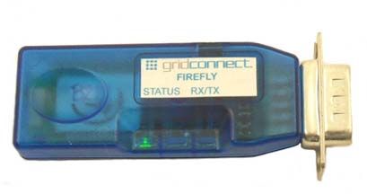
3-2 Firefly User Guide3.2 Overview
The following drawings show the top and bottom views of the Firefly. Note that the standard DB-9 Male
connector is shown. An optional DB-9 Female is available.
POWER JACK
RS232 DB9 Male
GREEN STATUS LED YELLOW RX/TX LED
Figure 1 - Firefly Top View
OPTION SWITCH COVER SCREW
Figure 2 - Firefly Bottom View
3.2.1 RS232 Physical Port Description
The pin names and descriptions are shown in the following table. Please note that many signal pins have no
connection.
Pin Description Source
1 -DCD Carrier Detect
(NOT Connected)
2 - RD Receive Data Attached Device (In)
3 - TD Transmit Data Host Device (Out)
4 - DTR Data Terminal Ready
(NOT Connected)
5 - GND Ground
6 – DSR Data Set Ready
(NOT Connected)
7 – RTS Request to Send Host Device (Out)
8 - CTS Clear to Send Attached Device (In)
9 –PWR 4-7 VDC External Power Supply
Table 1 - RS232 DB9 Male Pin Descriptions
Note: 4-7VDC will appear on Pin 9 when using an external power supply. Power can be supplied through the RS232
cable on Pin 9.
Firefly User Guide 3-3The standard configuration for RS232 connections with straight DB9 to DB9 connectors is shown below. It
is very important to note the direction of the data flow, as indicated by the arrows. The names of the signals
are often confusing so follow the direction of the data flow.
Note: Some of the signals have no connection in the Firefly. Only RD, TD, RTS and CTS are used.
IMPORTANT: If your device uses signals NOT available on the Firefly, you will have to make an
adapter cable or modify your hardware to allow it to operate with the Firefly. For additional
information, see Unused RS232 Signals on page 5-9.
Straight Cable DB9 to DB9
DTE Device (Computer) Signa l Direction DCE D evice (Modem)
Pin # DB9 Signal Nam es Pin # DB9 Signal Nam es
#1 N o Co nnection #1 N o Co nnection
#2 R eceive Data RD #2 R eceive Data RD
#3 Transmit Data TD #3 Transmit Data TD
#4 N o Co nnection #4 N o Co nnection
#5 Signal Ground GND #5 Signal Ground GND
#6 N o Co nnection #6 N o Co nnection
#7 R equest to Send RTS #7 R equest to Send RTS
#8 C lear to Send CTS #8 C lear to Send CTS
#9 4 -7VD C #9 4 -7VD C
Figure 3 - RS232 Straight Cable
3.2.2 Typical Application
A typical connection between a Computer (DTE) and a Modem (DCE) is shown below. The cable between
them is a straight cable. A straight cable means that pin 2 on one side goes to pin 2 on the other side. The
pins are connected straight through from one side to the other. Generally, a straight cable uses all 9 wires
and connects all RS232 signals as shown in Table 1 - RS232 DB9 Male Pin Descriptions.
Note: the term Modem is for reference only. The Firefly does not support Modems.
PC Modem
DTE Straight DCE
Cable
A Firefly wireless radio set will allow you to remove the straight cable and replace it with a wireless Firefly
connection. The connection looks something like the drawing below. Please note that the Firefly does NOT
use all the signals from the PC or the Modem. The Firefly uses only RX, TX, RTS and CTS.
PC Firefly Firefly Modem
DTE Straight Straight DCE
Cable Cable
DCE DTE
3-4 Firefly User GuideAn important point to consider in the drawing is that the Firefly connected to the Modem (DCE) has been
configured as a DTE device. This is done so that the signals from the Modem to the Firefly will match. You
can also match the signals by using a Modem crossover or Null Modem cable as shown below.
PC Firefly Firefly Modem
DTE Straight Cross over DCE
Cable Cable
DCE DCE
In the above diagram both Firefly devices are configured as DCE devices. The Crossover (Null Modem)
cable will match up the signals between the Modem and the Firefly.
Rule of Thumb: If your device plugs into the computer serial port with a straight cable and works normally,
the device is wired as DCE.
Check your cable wiring to determine if you are using a straight or crossover cable. A straight cable requires
one of the Firefly devices, the one connected to your device, to be configured as DTE. The other option is to
use a crossover cable and configure both Firefly devices as DCE.
The Firefly’s DB9 (Male) Serial Connector usually comes configured as a DTE device according to the
factory settings as shown in Table 1 - RS232 DB9 Male Pin Descriptions. Jumpers are available inside the
case to change the pin configuration of the Firefly (see section 3.5 for more information on how to access
and modify the jumpers).
3.2.3 Power Requirements
The Firefly’s Power Jack accepts 4VDC – 9VDC. The center pin of the power jack is for the input power
(typically +5V), while the outer cylinder should be connected to ground. The requirements can be met with
the supplied 5VDC, 300ma wall plug adapters.
Note: When using an external power supply, Pin 9 on the DB9 connector is connected to the external power supply. You
can remove the power to the pin by removing a small resistor. Remove R3 for units with DB9 Male or remove R30 for
units with DB9 Female.
The Firefly can be powered through the DB9 connector on Pin 9.
When actively transmitting or receiving data, the Firefly has a power draw of 30-50ma, depending on the
data rate. When idle, the power draw can be as low as 2ma.
Firefly User Guide 3-53.2.4 Status LEDs
The Firefly comes equipped with two status LEDs. The Green LED provides Bluetooth Device status,
while the Yellow LED provides status of the transmit/receive lines.
The Bluetooth Device status is indicated by the Green LED as shown in Table 2 - Status LEDs.
Table 2 - Status LEDs
Firefly Device Status Green LED Blink Rate
Configuring Fast, 10 times per second
Boot up, Remote Configurable 2 times per second
Discoverable/Idle 1 time per second
Connected On Solid
The Yellow LED shows the physical state of the TX and RX data pins, pulse stretched for improved
visibility. The Yellow LED blinks when data is transmitted or received on pins 2 and 3 of the serial port.
The Yellow LED works using a physical hardware connection, and does not depend on software from the
Firefly to make it operational.
3-6 Firefly User Guide3.3 Firefly Configuration Switches
4 - OFF=115K ON=9600
3 - AUTO MASTER
2 - AUTO DISCOVER
1 - FACTORY DEFAULTS
ON OFF
Figure 4 - Configuration Switches
For RS232 cable extender mode of operation, set one unit to Slave and the other unit to Auto Master. The
default settings are115200bps, Parity=None, Data bits = 8 bits (fixed), Stop bits 1 (fixed). If your device
uses a different baud rate, you will have to configure the Firefly for the new baud rate.
1- FACTORY DEFAULTS- Set this switch ON, power up the unit, and toggle the switch from ON to OFF
2 times to return the unit to factory settings.
2-AUTO DISCOVER MODE – In Slave mode, this will set a special class of device which is used by a
remote Firefly Master to auto connect. IF Switch 3 also ON, the device performs a search, store, and
connect to a remote slave which has switch 2 ON.
3- AUTO MASTER MODE- Firefly will act as master and auto-connect to a stored remote address. You
first set the Firefly address of the device to connect to using the SR command or have Firefly auto discover
and connect by setting this switch AND Switch 2 ON.
4- DEFAULT BAUD RATE – OFF = 115K (factory setting), ON = 9600. You can set a different baud rate
by software configuration.
*This is the Baud Rate of YOUR device. Other baud rates are available using the command mode.
Firefly User Guide 3-73.4 Cable Replacement Example
This section shows how to set up two units as a wireless cable replacement or cable extender. This example
assumes that one end of the cable is attached to a PC and the other to a compatible RS232 device, such as a
Modem, remote sensor, etc. Remember that the Firefly does not fully support modems. The term Modem is
just used for reference.
Since there is no way to determine what kind of compatible device you are using, you will have to verify the
cable and the pin connections are correct. In some cases, you will need a crossover cable or may have to
fabricate a custom cable in order to get the proper connections between your device and the Firefly radios.
See the Guide to RS232 at the end of the manual.
For this example, the PC side of the cable and radio connection will be referenced as the MASTER (PC).
The device connected to the PC will be referenced as the SLAVE (Modem). The PC is a DTE device, so the
Firefly radio attached to it must be a DCE device. The Modem is a DCE device, so the Firefly radio attached
to it must be a DTE device. Use the following drawing as a reference.
PC Firefly Firefly Modem
DTE Straight Straight DCE
Cable Cable
DCE DTE
The cables used in these examples are straight cables, meaning that pin 2 goes straight through to pin 2 on
the other end. The following drawing shows a 9-pin straight cable that can be used with the Firefly.
NOTE: The cable shows several pins with NO Connections. If your device requires these signals, you will have to make
a custom cable or modify your device to ignore the signals.
Straight Cable DB9 to DB9
DTE Device (Computer) Signa l Direction DCE D evice (Modem)
Pin # DB9 Signal Nam es Pin # DB9 Signal Nam es
#1 N o Co nnection #1 N o Co nnection
#2 R eceive Data RD #2 R eceive Data RD
#3 Transmit Data TD #3 Transmit Data TD
#4 N o Co nnection #4 N o Co nnection
#5 Signal Ground GND #5 Signal Ground GND
#6 N o Co nnection #6 N o Co nnection
#7 R equest to Send RTS #7 R equest to Send RTS
#8 C lear to Send CTS #8 C lear to Send CTS
#9 4 -7VD C #9 4 -7VD C
Note: Pin 9 is used to power the device over the RS-232 cable. If you are using an external power adapter, there will be
4-7VDC on Pin 9.
Here is a drawing of a cable that can be used for a wide variety of applications.
DTE Devic e (Computer) DCE Device
1 1
DSR 6 6 DSR
2 RXD RXD 2
RTS 7 7 RTS
3 TXD TXD 3
CTS 8 8 CTS
4 4
DTR 9 9 DTR
5 GND G ND 5
3-8 Firefly User Guide3.4.1 Configuration Procedures
1. Assign one of the Firefly radios as the MASTER and set the switches as shown below. The settings are
for 115K. Put Switch 4 in the ON position for 9600. This is the baud rate of the com port on your PC.
The baud rate must be the same on BOTH Firefly devices.
2. The Master device will be setup as a DCE device and should be connected to the PC side of the
connection.
MASTER (below)
4 - OFF=115K ON=9600
3 - AU TO MASTER
2 - AU TO DISCOVER
1 - FACTORY DEFAU LTS
ON OFF
Set the internal jumpers as shown below. If your device does not use flow control signals RTS and CTS, set
the jumpers as shown on the right. If you are not sure, use the drawing on the right.
PWR PWR
1 2 1 2
3 4 3 4
5 6 5 6
7 8 7 8
9 10 9 10
DCE RX=3, TX=2, RTS=8, CTS=7 DCE RX=3, TX=2
Connect the MASTER unit to the PC with a straight cable. See Figure 3 - RS232 Straight Cable.
3. Assign one of the Firefly radios as the SLAVE and set the switches as shown below. The settings are for
115K. Put Switch 4 in the ON position for 9600.
SLAVE (below)
4 - OFF=115K ON=9600
3 - AU TO MASTER
2 - AU TO DISCOVER
1 - FACTORY DEFAU LTS
ON O FF
Set the internal jumpers as shown below. Slave devices connected to a PC are generally configured as DCE
so the Firefly connected to your slave device should look like a PC or a DTE device. The drawings below
show DTE jumper settings.
If you are not using flow control signals RTS and CTS, set the jumpers as shown in the drawing on the right.
If you are not sure, use the drawing on the right.
PWR PWR
1 2 1 2
3 4 3 4
5 6 5 6
7 8 7 8
9 10 9 10
DTE Factor y Default, RX=2, TX=3, RTS=7, CTS=8 DTE Factory Default, RX=2, TX=3
Connect the SLAVE unit to the slave device with a straight cable. See Figure 3 - RS232 Straight Cable.
Firefly User Guide 3-94. Power up both devices.
5. The MASTER finds and stores the SLAVE address and auto connects. The GREEN LED on both units
will flash and within a short time should be on solid. The solid LED indicates the units are properly
linked.
6. Verify data flow by observing the YELLOW LED. Flashing indicates data flow, both transmit and
receive. The above configuration is for 115K Baud. Both units should flash the Yellow LED as data is
sent from one side to the other.
3.4.2 Link Test
Note: You can verify communications by connecting one Firefly to your PC and connecting a Loop-back
adapter to the other Firefly as shown in the drawing below. The Firefly not connected to the PC can be
configured as DCE or DTE. The loop-back adapter will take any received characters and send them back.
The loop-back adapter connects transmit and receive lines together and the RTS/CTS lines together. You
can make an adapter by using a DB9 Female connector and adding a wire between pins 2 and 3. If you are
using RTS and CTS signals, also add a wire from pin 7 to 8.
DB9 FEMALE REAR
1 2-3
6 7-8
LOOP BACK ADAPTER
In the drawing below, the slave device has a loop-back
Use a program like Hyperterminal to connect to the serial port of one of the Firefly radios, then you will see
a character displayed on the screen each time you send a character. See Hyperterminal Setup on page 6-18
for instructions.
First make sure the units are linked by observing the steady GREEN LED on both units. When you type a
character on the PC side, the yellow LED on the Firefly attached to it will blink. If the other Firefly is
configured properly, the yellow LED on it should also blink, indicating data is being received and
transmitted. Typing a character in Hyperterminal will send the character out the PC serial port to the
attached Firefly, through the radio link to the other Firefly, loop around from the receive line to the transmit
line and come back to the PC.
PC Firefly Firefly
Loop-Back
Adapter
DTE Straight
Cable
DCE DCE
3-10 Firefly User Guide3.5 Option Jumpers
The unit is generally delivered as a DTE device, with jumpers set for DTE. You can change this
configuration by removing the circuit board from the plastic case. Remove the screw from the back of the
case and set the configuration jumpers are shown in the table below.
PWR
1 2
3 4
5 6
7 8
9 10
DTE Factor y Default, RX=2, TX=3, RTS=7, CTS=8
Note: The table is for a Firefly with a DB9 MALE connector. See section Firefly with Female DB9 for information about
units with FEMALE DB9 connectors.
NAME DB-9 male DTE DTE DB-9 male DCE DCE Jumpers
Jumpers
DCD No Connection
RX 2 1-2 3 1-3
TX 3 3-4 2 2-4
DTR No Connection
GND 5
DSR No Connection
RTS 7 7-8 8 6-8
CTS 8 5-6 7 5-7
PWR Pin 9 4-7 VDC
Here is an example of a unit configured as DCE.
PWR
1 2
3 4
5 6
7 8
9 10
DCE RX=3, TX=2, RTS=8, CTS=7
Many RS232 cable systems use only Transmit, Receive, and Ground, which is commonly called a 3-wire
connection. The other control signals are not used or are tied together on the DB9 connector. To use a 3-
wire connection, the Firefly must see an active RTS and CTS connection. To internally tie RTS to CTS,
connect the Firefly option pins 9 and 10.
PWR
1 2
3 4
5 6
7 8
9 10
Figure 5 - DTE Configuration, Male DB9, 3-Wire
Firefly User Guide 3-11PWR
1 2
3 4
5 6
7 8
9 10
DCE RX=3, TX=2
Figure 6 - DCE Configuration, Male DB9, 3-Wire
3.5.1 Firefly with Female DB9
Note: The jumper settings for a Firefly with a FEMALE DB9 connector are different than a unit with a
MALE DB9.
The following drawings show the jumper settings for units with FEMALE connectors.
PWR
1 2
3 4
5 6
7 8
9 10
DTE Jumper Settings for FEMALE DB9
Figure 7 - DTE Configuration, Female DB9
PWR
1 2
3 4
5 6
7 8
9 10
DCE Jumper Settings for FEMALE DB9
Figure 8 - DCE Configuration, Female DB9
3-12 Firefly User Guide3.6 Firmware Configuration
Parameters, such as the Bluetooth Name, Class of Device and Serial Port settings can be viewed and
configured. This can be done locally through the serial port UART or from a remote Bluetooth RF link. To
access configuration, the Firefly must be in command mode by issuing ($$$). While in command mode
Firefly will accept ASCII bytes as commands.
3.6.1 From Local Serial Port
Connect a cable from a PC or from an ASCII terminal to the Firefly. Communication settings of your
program should match the stored settings. Once you change these parameters, they will be stored
permanently.
Note: If the Firefly is jumpered as a DCE device, then use a straight thru cable. If jumpered as a DTE device, then use a
cross-over or NULL Modem cable between the Firefly and your PC.
Default baudrate is 115200 (switch 4=OFF), no parity, 8 bits, 1 stop.
Local configuration works at any time the device does NOT have a Bluetooth connection, and also works
under certain conditions when the device is connected. If the device is in configuration mode and a
connection occurs, the device will exit configuration mode, and data will pass back and forth from the
remote device.
• Run your favorite terminal emulator, HyperTerminal or other program.
• Cycle power to the Firefly.
• Type $$$ on your screen (3 dollar signs).
• You should see the characters CMD returned to you.
This will verify that your cable and settings are correct. Valid commands will return an AOK. Errors in
format will return ERR, and unrecognized commands will return a ?. Type “h” to see a list of
commands, and “d” to see a summary of current settings.
To exit command mode, type “---“. (three minus or dash signs).
Firefly User Guide 3-133.6.2 Remote via Bluetooth
In some case it is very useful to be able to perform configuration remotely over a Bluetooth connection.
The Firefly has this capability. To utilize it, connect to the device over Bluetooth and using a remote
terminal emulator, perform the same steps as you would for local configuration. When finished configuring
be sure to either reset the device or send the “---“ command, which will exit configuration mode and allow
data to pass normally.
NOTE: The Firefly firmware implements a configuration timer window, which defaults to 60 seconds after
power up. The device will ignore configuration attempts after this timer expires, and data will flow back and
forth in normal mode. The timer can be set to any value from 0 (disable remote configuration) to 0xFF hex,
which allows continuous (no timeout) configuration.
WARNING: Configuration (local or remote) is NEVER enabled when the device is in auto-mode.
VALUE DESCRIPTION
(decimal)
0 No remote config, No local config when connected The unit must be in configuration mode to
1-252 Time in seconds from powerup to allow config remotely configure it via Bluetooth.
253 Continous config LOCAL only
254 Continuous config, REMOTE only • Set the Auto Master and Auto
255 Continuous config, both LOCAL and REMOTE Switches to OFF.
• Set the Baud Rate Switch to 115K
or 9600 and make sure HyperTerminal is also set to the same baud rate.
• Set the Factory Defaults switch to ON and cycle the power.
• Toggle the Factory Default switch from ON to OFF 2 times.
• The Green LED should be blinking at 2 times per second.
Make a connection via Bluetooth. Type $$$ on your screen (3 dollar signs). You should see CMD returned
to you. This will verify that your cable and settings are correct. Valid commands will return an AOK.
Errors in format will return ERR, and unrecognized commands will return a ?. Type “h” to see a list
of commands, and “d” to see a summary of current settings.
To exit command mode, type “---“. (three minus signs).
3.6.3 Modes of Operation
There are several modes of operation.
Slave mode – This is the default mode, whereby other Bluetooth devices can discover and connect to the
device. Outbound connections can also be made in this mode.
Master Mode - This mode is useful when the device only wants to initiate connections (not received them).
In this mode the device will NOT be discoverable or connectable.
Trigger Master Mode - In this mode, the device will automatically connect to the pre configured remote
slave address when a character (or characters) is received on the local UART. Connection will continue until
a configurable idle timer (1 to 255 seconds) determines that no more data is being received, or a
configurable BREAK character is seen.
Auto-connect Master Mode- This mode can be set by command or by Switch 3 on the Firefly. If auto-
connect mode is set, the device will initiate a connection to the pre-stored remote address immediately upon
power up. In this mode, data is passed without being interpreted by the Firefly (high speed), hence the
connection cannot be broken via command.
3-14 Firefly User GuideAuto Discovery/Pairing Mode -This mode can be set by command or by Switch 2. In this mode, if Master
Mode (or Auto-Connect) is set, the device will perform a device Inquiry Scan and search for a partner
Device with a special matching class. Once found, it stores the address of the device into the remote address
field then auto-connects to the remote device. If this mode is set on a slave device, the device will enter
slave mode with the special matching class and wait to be found by the master. This mode is usually set
once on both ends of a pair of devices for instant “cable replacement” and then removed.
Command Mode (vs Normal Data mode)- Upon powerup, the device will be in data mode. To enter
command mode, the characters “$$$” must be sent. The device will respond with “CMD”. To exit
command mode, send “---”. The device will respond with “END”. If configuring remotely over
Bluetooth, data will now pass back and forth over the serial port and the connection.
NOTE 1: You can enter command mode locally over the serial port at any time when not connected. Once a
connection is made, you can only enter command mode if the config timer has not expired. To enable
continuous configuration, set the config timer to 255. Also, if the device is in Auto Master mode3, you will
NOT be able to enter command mode.
NOTE 2: You can only enter command mode remotely over Bluetooth if you have made a connection and
sent the $$$ within the “config timer” window after powerup. The default config timer expires 60 seconds
after power up. Once the timer has expired, any data sent to the device will pass unmodified and
unrecognized by the command interpreter. The timer can be modified by command.
3.7 Factory Default Power up Settings
• Bluetooth Service Profile = Serial Port Profile (SPP)
• Mode = 0 Slave
• Baud Rate = 115200bps, Parity=None, Data bits = 8 bits(fixed), Stop bits 1 (fixed).
• Power Mode = Auto low power discoverable mode.
• Name of Device (local name) = Firefly-XXXX last 2 bytes of BT address
• Service Name = SPP
• Service Class=0000 (undefined service type)
• Major & Minor Class Of Device (COD) = 0x1F00 (unknown device type)
• Authentication Disabled
• Encryption disabled
• Discovery Enabled (0x0200 = window, fixed interval of 0x800= 1.28 Seconds)
• Connection Enabled (0x0200 = window, fixed interval of 0x800= 1.28 Seconds)
• Bonding Disabled (0)
• Config Timer=60 seconds
• SNIFF mode disabled
• Default PIN = “1234”
Note: Switch 1, Set ON at power up time and then toggled 3 times will change all settings above back to
their factory values (except the Device name). Device will reboot immediately upon detection of this mode.
Firefly User Guide 3-153.8 Example of a Master Discovery/Connection Sequence
From power up and no connection:
1) Perform an Inquiry to obtain BT_Address (unless it is already known).
Sent : $$$ // Places Radio in Command Mode
Reply:CMD
Sent : I,30 // Looks for Bluetooth devices
Reply:00A096112233,00000104,RN-112233DONE4. Firefly Command Reference
The commands are all single or 2 character commands, generally comma delimited. Commands and hex
input data can be upper or lower case. Text data, such as Bluetooth name, and pin code, are case sensitive.
Commands fall into 4 general categories:
SET COMMANDS - store information permanently and take effect after power cycle or software reset.
GET COMMANDS -retrieve the permanently stored information for display to the user.
CHANGE COMMANDS –temporarily change the value of serial baudrate, parity, etc.
ACTION COMMANDS – perform action such as inquiry, connect, etc.
SET COMMANDS
SA, Authentication. 1 to enable, 0 to disable. This will force authentication when any
remote device attempts to connect. Regardless of this setting, if a remote device forces
authentication, this device will respond with the stored pin code. Once a remote device
has exchanged pin codes with this device, a link key will be stored for future use. Up to
8 keys are automatically and permanently (in flash) stored in the device, in a first in,
first out fashion.
SB, Send BREAK. This is an immediate command, which can send a BREAK signal on the
TX . The timer is used to send a variable length BREAK signal.
Timer value Break length (in milliseconds)
1= 37ms, 2=18.5ms, 3=12ms, 4=9ms, 5= 7ms, 6=6ms.
Example : “SB,2” sends a 18.5 millisecond break signal.
SC, Service Class ( 16 bits, 11 used, this is used with Device Class below to create the 24-
bit class of device number.
Example : “SC,0002”
SD, Device Class (major and minor in a 16-bit word, used with service class above)
Example : “SD,8040”
SE, Encryption 1 to enable, 0 to disable
SF,1 Set Factory Defaults.
SI, Inquiry Scan Window. Sets amount of time device spends enabling inquiry scan
(discoverability). Minimum value is 0x0012, corresponding to about 1% duty cycle.
Inquiry interval is fixed at 0x1000, so time spent in inquiry is 0x12/0x1000 by default.
Maximum value is 0x1000, set to 0x0000 to disable inquiry scan and make device non-
discoverable.
SJ, Page Scan Window. Sets amount of time device spends enabling page scan
(connectability). Minimum value is 0x0012, corresponding to about 1% duty cycle.
Page Scan interval is fixed at 0x1000, so time spent in page scan mode is 0x12/0x1000
by default. Maximum value is 0x1000, set to 0x0000 to disable page scan and make
device non-connectable.
Firefly User Guide 4-1SL, Parity. Can be Even, Odd or None. Only the first character is needed.
Example : “SL,E” sets the parity to Even
S7,1 Enables 7 bit data mode
SM, Mode (0 = slave, 1 = master,2=trigger, 3 = auto)
Example: “SM,1” sets the mode to Master
SN, Friendly Name of the device, 16 characters maximum.
Example: “SN,MyDevice”
SP, Security Pin Code, 16 character maximum.
Example: “SP,secretcode”
SO, Extended Status String, 8 character maximum. Setting this string to from 1 to 8
characters will enable status messages to be sent to the local serial port. Two status
messages are sent, when a Bluetooth connection is established, the string ”
CONNECT” will be sent. Upon a Disconnect, the string DISCONNECT will be
sent. This parameter is useful, for example, when connected to a printer. The printer
can examine an escape sequence and if the is set to ESC%, the printer can parse
the ESC%CONNECT and ESC%DISCONNECT messages without interfering with
normal print jobs. In Trigger or Master modes, the first character of this string is used
as the BREAK connection character.
Example : “SE,ESC%”
SP, Security Pin Code, 16 character maximum
Example : “SP,secretcode”
SR, Remote Address. 12 hex digits, (6 bytes) no spaces or chars between.
Example : “SR,00A053112233”
NOTE: 2 special characters can be used here:
“SR,Z” will erase any stored address.
“SR,I” will write the last address seen by using the Inquiry command.
This can be helpful when you just have 1 other device in range and want to quickly store
and connect to it.
SS, Service Name (1 to 16 characters ).
Example : “SS,SerialPort”
ST, Config Timer, # of seconds ( range= 0 to 255 decimal,, default = 60 decimal) to allow
remote configuration over Bluetooth after power up in Slave Mode. In all Master
modes, the remote config timer is set to 0 (no remote configuration). In Trigger Master
Mode, this Timer is used as an Idle timer to Break the connection after the timer expires
with no characters being received.
Example : “ST,0” disables remote configuration
Example : “ST,255” enables remote configuration forever
SU, Baudrate, {1200, 2400, 4800, 9600, 19.2, 38.4, 57.6, 115K, 230K, 460K, 921K }, only
the first 2 characters are needed.
Example : “SU,96” sets the baudrate to 9600 baud.
4-2 Firefly User GuideSW, Enable low power SNIFF mode. Set this to either 1= SNIFF enabled, or 0 = Sniff
Disabled. Default is 0=disabled. SNIFF mode allows extreme low power operation.
Device goes into a deep sleep, and wakes up approx every 250ms to send/receive chars.
NOTE: setting this mode can cause latency issues, and dropped bytes/loss of
performance in cases where large amounts of data are being transferred. This mode is
only recommended for low speed, small byte transfers.
SX, Bonding enabled, creates a single stored connection pair with a remote device.
SZ, Raw Baudrate (decimal) allows entering of non-standard baud rates. Based on the
formula: num = Baudrate * 0.004096.
S$, Configuration detect character. This allows a change from the default $$$ to some other
character. Factory defaults returns the device to $$$.
GET COMMANDS
D Display basic settings. Address, Name, UART Settings, Security, Pin code, Bonding,
Remote Address. This command is an easy way to check the configuration.
E Display extended settings. Service Name, Service Class, Device Class, Config Timer,
Link Timer, Status, Link Keys, DeBug Mode.
O Display other settings. Config character, IO port values, debug mode.
G Display stored settings . These commands correspond to the SET commands above.
(See below for exceptions)
Example: “GS” will return 1 or 0 depending on the value of security.
Example: “GP” will return the pin code.
GB Returns the Bluetooth Address of the device. Example: 00A0961D97D6.
GK Returns the current connection status: 1=connected, 0 = not connected.
G& Return a hex byte containing the value of the PIO Pins
V Return the software release version.
Ver 2.12 10/04/2004
© Roving Networks
CHANGE COMMANDS
U,,Temporary UART Change, will change the serial parameters immediately, but not store
them. Command will return “AOK” at current settings, then switch to new.
Example: “U,9600,E” Sets baudrate to 9600, parity even.
Firefly User Guide 4-3ACTION COMMANDS
$$$ Enter command mode. Characters are PASSED until this exact sequence is seen. If any
bytes are seen before these chars, or after these chars, in a 1 second window, command
mode will not be entered and these bytes will be passed on to other side.
--- Exit command mode. “END” will be displayed. If connected over BT, data will now
pass in both directions.
C{,} connect. The device will attempt to connect to the remote stored BT address, or an
optional address can be entered directly.
I, performs an inquiry scan. Default time is 10 seconds, maximum is 48. is
optional class of device, 0 or no entry looks for all device classes. A maximum of 9
devices will be returned. As devices are found, they are displayed in the format below:
, ,
00A053000123,MySerialPort,72010C
IN, performs an inquiry scan, does not return the Bluetooth NAME ( returns much faster,
since name requires a remote lookup for each device found).
IR Performs an inquiry scan, with a COD of 0x001F00, which is the default COD for
Roving Networks Serial adapters and modules.
IS Performs an inquiry scan, with a COD of 0x0055AA, which is the special COD used by
Roving Networks Serial adapters and modules to enable “instant cable replacement”.
H Will print out a list of Help commands and their basic syntax.
K, Kill (disconnect) from the current connection.
P, Pass thru, sends any chars along up to a CR or LF while in command mode.
Q- Causes device to be non-discoverable and non-connectable (temporarily). Does not
survive a power cycle or reset. Used with the Z command below
R,1 Forces a complete reboot of the device (similar to a power cycle)
& - Returns the value of the switches on Firefly, or value of PIO3,4,6,7 on other modules.
Z- Enters low power deep sleep mode (100ua) can only be exited by toggling the RESET
pin on the module or power cycling the device. To get the lowest power mode, first
issue a Q, then a Z.
F,1 Enter Fast data mode, end configuration
4-4 Firefly User Guide4.1.1 Command Summary
SET COMMANDS are stored in flash and only take effect AFTER reboot
Example: SU,96 sets UART Baudrate to 9600
SN,myname sets Bluetooth name to “myname”
SA,1 enables secure authentication and encryption
SP,secret sets security pincode to “secret”
SF,1 restores all values to factory defaults
CMD VALUE TYPE DEFAULT DESCRIPTION
SA 0,1 dec 0 (disabled) Enable Authentication and Encryption
SB timer NA Send Break
SC Hex 0x0000= unknown Service Class
SD Hex 0x1F00= undefined Device Class
SE Text Null Ext conn/discon Status
SF 1 dec Reset to Factory Defaults
SI Hex word Hex 0x0200 Inquiry Scan Window
SJ Hex word Hex 0x0200 Page Scan Window
SL E,O,N char N (8 Data bits, 1 Stop Parity, Even, Odd, or None
Bit)
SM 0,1,2,3 dec 0=Slave Mode (0-slave, 1=master, 2=trig, 3=auto)
SN string 1-16 char Firefly-xxxx Bluetooth Name
SO Text Conn/Disconn status Null = no status string
SP string 1-16 char 1234 Security Pin Code
SR string 12 chars NOT SET Remote Address (123456789ABCDEF)
SS Text SPP Service Name
ST word seconds 60 Config Timer(0=no config, 255=always on)
SU string 2 char 115K Baudrate:1200,2400,4800,9600,384k,576k
115k,230k,460k)
SW Num SNIFF mode 0=disabled
SX 0,1 dec 0 (disabled) Bonding (locks to a single remote address)
SZ Num Raw Baudrate
CMD DESCRIPTION
D Basic Settings
E Extended Settings
O Other Settings
G A single setting matching the commands above
H Help
GB Bluetooth Address of this device (00A0961D97D6)
GK Connection Status
G& I/O Ports
V Firmware Revision (Ver 4.00 06/02/06)
Firefly User Guide 4-5CMD VAL1 VAL2 DESCRIPTION C Connect to Remote Address( in Master Mode only) F,1 Enter Fast data mode, end configuration H Help, Show list of commands I Iquiry Scan, time= xx seconds ,optional COD filter IN
4.1.2 Testing the COM Port
By pairing a Bluetooth USB device on your computer to a Firefly remote device, you have established a
Bluetooth wireless connection to the remote device. To test the remote device, you can use HyperTerminal
to send and receive ASCII characters.
A quick way to test a remote Firefly device is to use a loop-back plug. This is just a DB9 Female plug with
two jumpers: Pin 2 tied to Pin 3 and Pin 7 tied to Pin 8. This ties the receive line back to the transmit line so
that any character received by the remote device is instantly sent back. This jumper plug also ties the RTS
and CTS lines together.
Start HyperTerminal and configure the Serial Properties to use the COM port assigned when you created the
link. In the previous section, COM3 was configured to connect to the Firefly-97E9. Make sure you set the
Baud Rate to match the Firefly settings. When HyperTerminal indicates it is connected, you can type
characters and see the characters being returned by the remote unit. See Hyperterminal Setup on page 6-18
for instructions.
Note: make sure Local Echo is turned OFF, otherwise you will get two characters.

                   Firefly User Guide                                                                         4-7
5. Guide to RS-232
Confused about how to connect your device to a Firefly? Don’t feel bad because RS-232 signal names are
very confusing. You would think that the data coming out of a device would be called Transmit Data and
data going into a device is Receive Data. It depends on which side of the link you are on, the Data Terminal
Equipment (DTE) side or the Data Communication Equipment (DCE) side. Even the equipment naming
convention is confusing.
To help you understand how a signal gets from your computer to the device on the other side of a
communication link (cable, radio, modem, etc.), this section presents some very basic cable diagrams and
shows how the signals move from one point to the other.
First, here is drawing of a typical PC connected to a Modem using a straight cable. A Modem is used as
reference because that is where all the naming conventions started. The cable diagram shows the wiring
standard for a 9-pin RS-232 cable. The gender of the cable doesn’t matter at this point.
PC Modem
DTE Straight DCE
Cable
Stra ight C able DB9 to D B9
DTE Device (Computer) DCE D evice (Modem)
Pin Signal Names Signal Dire ction Pin Signal Names
#1 Carrie r D etect CD #1 Carrie r D etect CD
#2 Receive D ata RD #2 Receive D ata RD
#3 Transmit Da ta TD #3 Transmit Da ta TD
#4 Data Terminal Ready DTR #4 Data Terminal Ready DTR
#5 Signal Ground GN D #5 Signal Ground GND
#6 Data Set Ready DSR #6 Data Set Ready DSR
#7 Request to Send RTS #7 Request to Send RTS
#8 Clear to Send C TS #8 Clear to Send CTS
#9 Ring Indicator RI #9 Ring Indicator RI
Figure 9 - Straight Cable
All signal names are derived from the early naming convention used to connect a PC to a Modem. The
signals from the PC are shown on the left side and the signals to the Modem are shown on the right. The
signal names on both sides of the connection have the same name. For instance, Pin 3 on the computer side
is Transmit Data and it is connected to Pin 3 Transmit Data on the Modem. The reference is the PC, so that
when you see Transmit Data it means data is going from the PC to the Modem. In the same way, Receive
Data means data is coming from the Modem to the PC. The arrows in the drawing indicate the direction of
the data flow.
The Modem in the previous drawing can be replaced by any device that uses RS232 signals. We use the
term Modem as a reference only. You must match the signals from the PC to the RS232 device.
Most of the Modem control signals, like Ring Indicator, are no longer used.
5-8 Firefly User GuideWhen illustrating a cable connection, the Computer PC side is generally named DTE and the Modem side is
named DCE. For reference, DTE means Data Terminal Equipment and DCE means Data Communication
Equipment. The names don’t really help a lot but we are stuck with them. Any connection between two
RS232 devices must follow the convention of connecting a DTE device to a DCE configured device. For
example, if you connect an embedded controller to a robot, one side must be a DTE device and the other a
DCE.
5.1.1 Unused RS232 Signals
You can’t really connect one RS232 device to another RS232 device. Why not? The naming convention
again causes problems. RS232 generally means the signal levels used by the devices. An RS232 transmitter
can send data to an RS232 Receiver. However, there are many signal names for the RS232 standard and
many RS232 devices use only the ones they need. One device might use Transmit, Receive and Ground and
you can call it an RS232 interface. Another device uses Transmit, Receive, RTS and CTS for flow control.
It is also an RS232 interface. But they cannot be connected together because one device lacks the circuits to
handle the RTS and CTS signals. There are ways to compensate for the lack of interface circuits.
Here is an example of two devices, both with an RS232 interface but one of them does not use all of the
interface signals. The device on the left is a DTE or master device and requires all the RS232 signals but the
device it is connected to, possibly your device, does not have all the necessary signals. As you can see, your
device (in the example) does not have Carrier Detect or Data Set Ready or Ring Indicator, and doesn’t use
Data Terminal Ready.
DTE Device (Computer) DCE D evice (Yo ur D evice)
Pin Signal Names Signal Dire ction Pin Signal Names
#1 Carrie r De tect CD #1
#2 Rece ive D ata RD #2 Rece ive D ata RD
#3 Transmit Data TD #3 Transmit Data TD
#4 Data Terminal Ready D TR #4
#5 Signal Gro und GND #5 Signal Gro und GND
#6 Data Set Ready DSR #6
#7 Request to Se nd RTS #7 Request to Se nd RTS
#8 Clear to Se nd C TS #8 Clear to Se nd CTS
#9 Ring Indica tor RI #9
How can you make these two devices work together? You can wire the cable between the devices in such a
way as to make the master think the signals are coming from the slave device. First, take a look at the cable
that connects the slave device to the master. Note there is no connection for Carrier Detect on pin 1, no
connection for Data Terminal Ready on pin 4, etc. This cable uses four signals, RXD, RTS, TXD and CTS.
DTE Device (Computer) DCE Device
1 1
6 6
2 RXD RXD 2
7 RTS RTS 7
3 TXD TXD 3
8 CTS CTS 8
4 4
9 9
5 GND G ND 5
RS232C STRAIGHT CABL E
You need to add some additional wires to the cable so that the master side thinks it is receiving the right
signals. Here is an example of how to modify the cables to make the connection work. Since the connected
Firefly User Guide 5-9device, the DCE device, does not have a DSR signal on pin 4, you can add jumper wires on the DB9
connectors to provide the proper signal levels. In this case, connect pin 4 and pin 6 to provide a DSR signal.
Add the jumper wires to each side of the cable connection, just in case both sides need an unused signal.
DTE Device (Computer) DCE Device
1 1
DSR 6 6 DSR
2 RXD RXD 2
7 RTS RTS 7
3 TXD TXD 3
8 CTS CTS 8
4 4
DTR 9 9 DTR
5 GND GND 5
Some devices do not have hardware flow control signals RTS and CTS available. In that case you can add
more jumper wires to connect those signals. Here is an example of a cable with jumpers for RTS and CTS.
The example is called a 3-wire cable adapter.
DTE Devic e (Computer) DCE Device
1 1
DSR 6 6 DSR
2 RXD RXD 2
RTS 7 7 RTS
3 TXD TXD 3
CTS 8 8 CTS
4 4
DTR 9 9 DTR
5 GND G ND 5
Some computer devices may require the Carrier Detect CD signal from the slave. Again, you will have to
modify a cable to provide this signal. Here is an example of how to modify a cable to add the CD signal.
DTE Devic e (Computer) DCE Device
CD 1 1
6 6 DSR
DSR 2 2
RXD RXD
RTS 7 7 RTS
3 TXD TXD 3
CTS 8 8 CTS
4 4
DTR 9 9 DTR
5 GND GND 5
5.1.2 Firefly Signals
The Firefly does not use all the 9-pin cable signals. This simplifies the connection to a Firefly. The table
below shows the provided signals.
5-10 Firefly User GuideStra ight C able DB9 to DB 9
DTE Device (Computer) DCE D evice (Modem)
Pin Signal Names Signal Dire ction Pin Signal Names
#1 #1
#2 Rece ive D ata RD #2 Rece ive D ata RD
#3 Transmit Data TD #3 Transmit Data TD
#4 #4
#5 Signal Gro und GND #5 Signal Gro und GND
#6 #6
#7 Request to Se nd RTS #7 Request to Se nd RTS
#8 Clear to Se nd C TS #8 Clear to Se nd CTS
#9 #9
5.1.3 Firefly Radio
A wireless radio link should allow you to unplug the cable from the PC to the modem and replace it with a
pair of radios.
Here is what the connection will look like.
PC Firefly Firefly Modem
DTE Straight Straight DCE
Cable Cable
DCE DTE
The link on the left side has the Firefly shown as a DCE device and the link on the right shows the Firefly as
a DTE device. Why? When a single cable was used, the PC is a DTE device connected to the Modem which
is a DCE device. Therefore, you have to connect the PC to a DCE device.
The Firefly radios can be configured to be either version so that they can be configured to connect a wide
range of devices.
The units come from the factory configured as DTE. Therefore, the radio on the left link must be changed to
a DCE device. This is done with internal jumpers discussed in a previous section.
Here is what the connection looks like.
NOTE: Do not confuse the electrical drawings of the jumpers with the physical jumper settings.
PC Co nnected to a DC E Firefly
DTE Device (Computer) Signa l Direction DCE D evice (Firefly)
Signa l Names Pin # Pin # Jumper Signa l Names
Receive Data R D #2 #2 2 1 Receive Data R D
Transmit Data TD #3 #3 3 4 Transmit Data TD
Signa l Ground GN D #5 #5 Signa l Ground GN D
Reque st to Send RTS #7 #7 7 8 Reque st to Send RTS
Clear to Send CTS #8 #8 6 5 Clear to Send CTS
Jumper
Take a look at the Transmit Data coming from the Computer side. It is connected to cable pin 3 and the flow
shows it going out from the Computer. It connects to pin 3 on the other end of the cable attached to the
Firefly. The internal jumper routes the signal from pin 3 to the Receive Data line (Jumper 1-3). In this
configuration, the link works properly.
Firefly User Guide 5-11Now you have to consider what the radio link does to the data. Basically, it extends the cable connection so
that Transmit Data coming in on cable pin 3 should go across the radio link and come out the other side on
pin 3. Let’s take a look at the connection to see how it works.
In the following drawing, the Firefly is configured as a DTE device because the Modem on the other end of
the cable is a DCE device. Since the Computer is sending out Transmit Data on pin 3, you expect to see
Transmit Data on pin 3 on the other side of the link. In the drawing below, Transmit Data comes across on
pin 3, goes straight through the jumpers (Jumper 3-4) to the Transmit Data line and out to the Transmit Data
pin 3 on the Modem. The signal flow is correct and the link should work properly.
BluePort D TE connected to a D CE Device
DTE Device (Firefly) Signa l Direction DCE D evice (Modem)
Pin # Jumper Signa l Names Pin # Signa l Names
#2 2 1 Receive Data R D #2 Receive Data R D
#3 3 4 Transmit Data TD #3 Transmit Data TD
#5 Signa l Ground GN D #5 Signa l Ground GN D
#7 7 8 Reque st to Send RTS #7 Reque st to Send RTS
#8 6 5 Clear to Send CTS #8 Clear to Send CTS
5-12 Firefly User GuideYou can also read