SPIDER - User manual - ACOWA Instruments
←
→
Page content transcription
If your browser does not render page correctly, please read the page content below

User manual

SPIDER

User manual

   User manual
   ACOWA SPIDER / AcowaZoo
   072020

                                                                                                                      1
      ACOWA INSTRUMENTS, Industrivej 10, 8305 Samsø - VAT-no: 36562919 – mail: info@acowa.dk – Phone: +45 7221 7979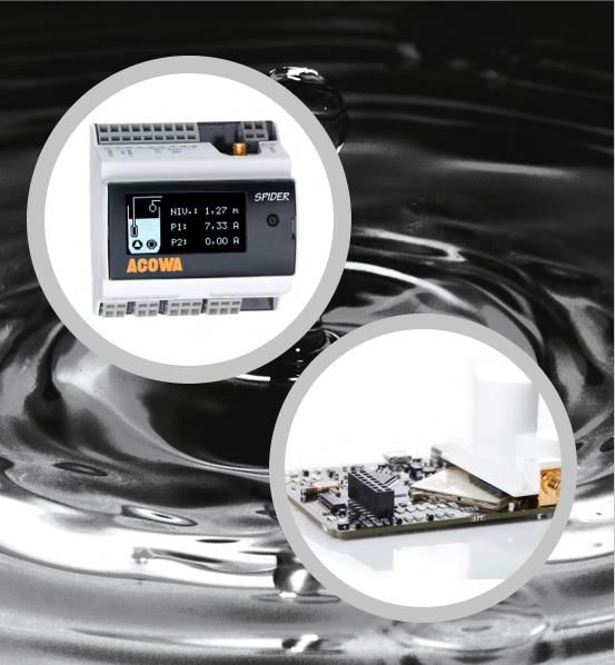
User manual

 Table of Content
 Content
 SPIDER ................................................................................................................... 4
   About SPIDER ................................................................................................................................................. 4
   Funktions ....................................................................................................................................................... 4

 Installation............................................................................................................. 5
      Power supply ............................................................................................................................................. 5
      Psychical specifications.............................................................................................................................. 5
      Installation environments.......................................................................................................................... 5
      Build-in power supply ................................................................................................................................ 5
      Analog input .............................................................................................................................................. 6
      Digital input with the option of 0-10V analog ........................................................................................... 6
      Digital output ............................................................................................................................................. 6

 Operation .............................................................................................................. 7
      Overview .................................................................................................................................................... 7
      The red button ........................................................................................................................................... 7
      SPIDER diodes ............................................................................................................................................ 8

 Externel unites ....................................................................................................... 8
   I/O module..................................................................................................................................................... 8
      Installation. ................................................................................................................................................ 8
   Communication via ModBus ......................................................................................................................... 9
      Installation instructions. ............................................................................................................................ 9

 Displays ............................................................................................................... 10
   Display 2,4” OLED ........................................................................................................................................ 10
     Installation instructions. .......................................................................................................................... 10
     Menu structure for the 2,4” OLED Display .............................................................................................. 10
   Display EAGLE HMI 7” .................................................................................................................................. 11
     Installation guide ..................................................................................................................................... 11
     Menu structure for 7” EAGLE HMI Display .............................................................................................. 11

 AcowaZoo ............................................................................................................ 18
   Connecting to a PC ...................................................................................................................................... 18
     USB connection ....................................................................................................................................... 18
     TCP Connection ....................................................................................................................................... 18
   AcowaZoo Installation ................................................................................................................................. 18

                                                                                                                                                                     2
          ACOWA INSTRUMENTS, Industrivej 10, 8305 Samsø - VAT-no: 36562919 – mail: info@acowa.dk – Phone: +45 7221 7979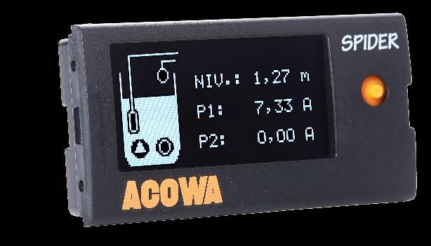
User manual

      Driver installation .................................................................................................................................... 18
      Program installation ................................................................................................................................ 18

 Setup ................................................................................................................... 20
   AcowaZoo user interface ............................................................................................................................. 20
     Overview .................................................................................................................................................. 20
     Function buttons ..................................................................................................................................... 20
     Function menu......................................................................................................................................... 22
     Settings selection..................................................................................................................................... 24
     SPIDER details .......................................................................................................................................... 24
   Input and output Settings............................................................................................................................ 25
     Analog Input (AI1).................................................................................................................................... 25
     Digitale Input (I1–I6) ................................................................................................................................ 26
   Digital output ............................................................................................................................................... 30
   Contact device via TCP/IP ............................................................................................................................ 33
   Device settings / advanced settings ............................................................................................................ 34
     Reports and alarms:................................................................................................................................. 34
     Reverse Comm:........................................................................................................................................ 34
   Show Status ................................................................................................................................................. 37
     Online status ............................................................................................................................................ 37
   Graphical and schematic view ..................................................................................................................... 38
   Applications ................................................................................................................................................. 39
     Pump control: .......................................................................................................................................... 39
     Flow interface: ......................................................................................................................................... 39
     Additional Options:.................................................................................................................................. 40
     Groundwater lowering: ........................................................................................................................... 40
     Monitoring: .............................................................................................................................................. 41
     Compressor control: ................................................................................................................................ 41
     Concertor control: ................................................................................................................................... 41
   Other functions............................................................................................................................................ 43
     High level switch version 2 (advanced function): .................................................................................... 43
     SPIDER pump control using only level switch:......................................................................................... 44

 Register list ”quick-guide" .................................................................................... 49
   Analog .......................................................................................................................................................... 49
   Input ............................................................................................................................................................ 49
   Output ......................................................................................................................................................... 49
   Pump control ............................................................................................................................................... 49
   External gauges............................................................................................................................................ 50
   Converters ................................................................................................................................................... 50
   Pump word .................................................................................................................................................. 50
   Time / Date .................................................................................................................................................. 51
   SPIDER status: Register 92 ........................................................................................................................... 51

                                                                                                                                                                       3
          ACOWA INSTRUMENTS, Industrivej 10, 8305 Samsø - VAT-no: 36562919 – mail: info@acowa.dk – Phone: +45 7221 7979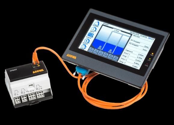
User manual

 SPIDER
 About SPIDER
 SPIDER is a universal control with functions for pump control, data collection, alarm management,
 groundwater lowering etc.

 SPIDER is developed and produced in Denmark. SPIDER complies with all specifications regarding
 placement of electronic components in harsh environments.

 Funktions
    •    Advanced 1 and 2 pump control with empty/fill function and internal pump alternation.
    •    Build-in GSM/GPRS Modem.
    •    Multiprotocol, Modbus RTU/TCP & COMLI. SPIDER auto-detects the protocol used by the SCADA
         system.
    •    Click connection for a joystick-equipped graphic 2,4” OLED display directly onto SPIDER.
    •    Possibility to connect a 7” color touch-sensitive display via a serial HMI interface.
    •    Validated flow calculation where the pump’s exact capacity is calculated.
    •    Status words function that can take a failed pump out of operation.
    •    Emergency control function via a float switch when a pressure transmitter fails.
    •    Indication of required pump service where SPIDER informs that a pump has reduced capacity.
    •    Built-in power bank that maintains control during power failures and sends an alarm to SCADA.
    •    Daily running of pumps so they do not seize after long idle periods.
    •    Daily depth pumping to avoid top sediment layer.
    •    Choice of various start levels to prevent sediment accumulation at liquid entrance point.
    •    Configuration of SPIDER via ACOWA ZOO software, both locally (Micro USB cable) or via server setup.

                                                                                                                        4
        ACOWA INSTRUMENTS, Industrivej 10, 8305 Samsø - VAT-no: 36562919 – mail: info@acowa.dk – Phone: +45 7221 7979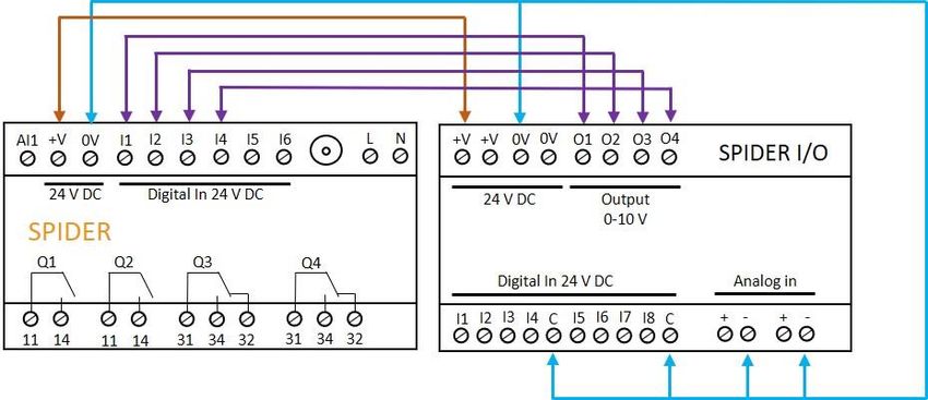
User manual

 Installation
 Power supply
 SPIDER must be connected to a supply voltage according to the specifications below.

  Voltage supply                              230 VAC +10% / -20%
  Frequency                                   50/60Hz
  Input current consumption                   0,004 -> 0,06A
  Startup current
User manual

 Analog input
 SPIDER is designed with one analog input 0-20mA / 4-20mA.

  Numbers of analog mA inputs                 1
  Electrically isolated                       No
  Measuring range                             0 / 4 – 20mA
  Input impedance                             Approx. 100 Ω
  Measuring accuracy                          +/- 1% of FS
  Signal area                                 0-24mA / 0 – 30 V DC
  Signal frequency                            Maximum of 100 Hz
  Cable / signal length                       Maximum of 100m

 Digital input with the option of 0-10V analog
 SPIDER has 6 digital inputs, all of which can be selected as 0-10V analog voltage inputs.

  Numbers of digital inputs                   6
  Electrically isolated                       No
                                              Low < 5 V / < 1 mA
  Digital signal
                                              High> 12 V / > 4 mA
  Analog measuring range                      0 – 10 V DC
  Analog signal impedance                     Approx. 20KΩ
  Measuring accuracy                          +/- 1% of FS
  Signal range (min / max)                    0 – 30 V DC
  Signal frequency                            Maximum of 100 Hz
  Cable / signal length                       Maximum of 100m

 Digital output
 SPIDER is equipped with 4 digital relay outputs.

  Numbers of digital outputs                  4
  Electrically isolated                       Yes
  Insulation voltage                          4 KV
  Relay type                                  Relay output
  Kabel / signal length                       Maximum of 100m
  Relay NO #11 and #21
                                              Maximum of 10 A @ 230Vac - AC1
                                              Maximum of 500 W @ 230Vac - AC3
  Constant load
                                              Maximum of 1 A @ 48 VDC
                                              Maximum of 10 A @ 24 VDC
  Minimum current                             5 mA @ 10 V
  Max. Start-up current                       18A
  Switch speed                                Maximum of 1 Hz
  Relay NO #31 and #41
                                              Maximum of 2 A @ 230Vac - AC1
  Constant load                               Maximum of 100 W @ 230Vac - AC3
                                              Maximum of 1 A @ 30 VDC
  Minimum current                             5 mA @ 10 V
  Max. Start-up current                       6A eller 10A @ 20 mS
  Switch speed                                Maximum of 10 Hz

                                                                                                                        6
        ACOWA INSTRUMENTS, Industrivej 10, 8305 Samsø - VAT-no: 36562919 – mail: info@acowa.dk – Phone: +45 7221 7979
User manual

 Operation
 Overview

   Digital Inputs             Power supply                Analog inputs              Digital outputs              USB connection

 The red button
 SPIDER has a red button on the print next to the SIM card where it is possible to restart / reset SPIDER.

 The red button on the top print has the following functions:

                                                             The number of             Function
                                                             activations within
                                                             a 5 sec. range.
                                                                       1               Reset modem
                                                                                       Enable / disable display interface
                                                                        3
                                                                                       (baud rate 57600 bps)
                                                                                       Enable HMI interface
                                                                        5
                                                                                       (baud rate to 38400 bps)
                                                              Hold the button          SPIDER restarts. Used in connection
                                                               in for 10 sec.          with fw-update or similar.

                                                                                                                               7
        ACOWA INSTRUMENTS, Industrivej 10, 8305 Samsø - VAT-no: 36562919 – mail: info@acowa.dk – Phone: +45 7221 7979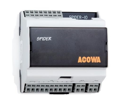
User manual

 SPIDER diodes
                                                                                   Status

                                                                                   Flashes every 5 seconds: status to
                                                                                   indicate that the device is working.

                                                                                   Double flash means that the HMI
                                                                                   interface / Oled display is enabled.

                                                                                   Net-status

                                                                                   Flashing fast (2 times per second)
                                                                                   modem is not connected to the GSM
                                                                                   mast.

                                                                                   Flashes slowly (once per second) and is
                                                                                   connected to the GSM mast.

 Modem-status flashes when a modem is connected to the GSM mast and a signal strength is detected.

 Externel unites
 I/O module
 For connections of more signals, it is possible to connect an I/O
 module with multiple digital- and analog inputs.

 The module allows for a total of 10 digital inputs and a further 2
 analog 0-10 V DC inputs.

 For setting up the extra inputs go to page 24.

 Installation.
 For correct installation, the I/O module must be connected to the
 SPIDER control the following way.

                                                                                                                             8
        ACOWA INSTRUMENTS, Industrivej 10, 8305 Samsø - VAT-no: 36562919 – mail: info@acowa.dk – Phone: +45 7221 7979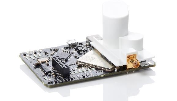
User manual

 Communication via ModBus
 The SPIDER can, via the ModBus-RTU protocol, communicate with
 several types of external devices. The SPIDER always writes the values
 in the same register for the same type of equipment, regardless of the
 brand of the device being communicated with (page 35). To
 communicate via ModBus, a serial interface module for the SPIDER is
 required.
 Installation instructions.
 For correct installation, remove the transparent front cover on the
 SPIDER. The interface module is then clicked on, so that the RJ45 socket
 is located to the right. The interface module comes with 1.5 meters of
 cable for RS485 connection between HMI and ModBus modules.

  SPIDER INTERFACE MODUL                                                 ID 1
  Pin 4                                                                  Blue
  Pin 5                                                                  White
  Pin 8                                                                  Brown
  EAGLE HMI                                                              MASTER
  Pin 1                                                                  Blue
  Pin 6                                                                  White
  Pin 5                                                                  Brown
  DANFOSS FC 202                                                         ID100                             ID101
  Terminal 69                                                            Blue
  Terminal 68                                                            White
  Terminal 61                                                            Brown
  SCHNEIDER ALTIVAR                                                      ID100                             ID101
  Terminal 5                                                             Blue
  Terminal 4                                                             White
  Terminal 8                                                             Brown
  ABB ACS550                                                             ID100                             ID101
  Terminal??                                                             Blue
  Terminal??                                                             White
  Terminal??                                                             Brown
  XYLEM CONCERTOR                                                        ID100                             ID101
  Terminal??                                                             Blue
  Terminal??                                                             White
  Terminal??                                                             Brown
  SIEMENS FLOW MAG6000                                                   ID200
  Terminal 93                                                            Blue
  Terminal 92                                                            White
  CARLO GAVAZZI EM430 BIMÅLER                                            ID10
  Terminal 9                                                             Blue
  Terminal 8                                                             White
  Terminal 10                                                            Brown
  KAMSTRUP MÅLER
  Terminal 137                                                           Blue
  Terminal 138                                                           White
  Terminal 139                                                           Brown

                                                                                                                        9
        ACOWA INSTRUMENTS, Industrivej 10, 8305 Samsø - VAT-no: 36562919 – mail: info@acowa.dk – Phone: +45 7221 7979
User manual
Displays
Display 2,4” OLED
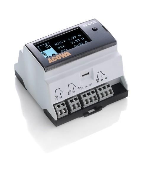
SPIDER comes with two different types of displays but can also work without a display.
Display for direct mounting on SPIDER is a 2.4 "OLED display. The
display has different screen settings and can be operated with the
joystick on the right side.
There is a pause screen which disables the normal screen display
after 5 minutes. After this it goes to the screen saver picture where
level is displayed in different places on screen.
Installation instructions.
For correct installation, remove the transparent front cover on the SPIDER. The interface module is then
clicked on, so that the joystick is located to the right.
Menu structure for the 2,4” OLED Display
Coming soon
10
ACOWA INSTRUMENTS, Industrivej 10, 8305 Samsø - VAT-no: 36562919 – mail: info@acowa.dk – Phone: +45 7221 7979User manual
Display EAGLE HMI 7”
SPIDER can also be delivered with a larger 7” HMI display where a
larger graphic image can be designed. It is possible to
design customized graphics.
A serial overprint is required. This is easily clicked
on the SPIDER as well as cable sets and HMI display.
SPIDER HMI kit incl. cable sets, SPIDER serial print
incl. 1.5m cable set
Installation guide
EAGLE HMI is not be supplied via the internal power supply of SPIDER. We recommend a 24V DC power
supply of min. 500mA.
Menu structure for 7” EAGLE HMI Display
Function-
Submenu functions
buttons
(Page 9) (Page 10-15)
Function buttons
HOME
Overview image of the pumping station. At startup, the controller will start in this page.
The panel reads the setup configuration in SPIDER and creates the image from it (Page 11)
SETUP
This menu contains all submenus for manual setup of the controller (Page 12)
GRAPH
The submenu contains graphs of level, inlet flow, Power P1 and Power P2 (Page 15)
11
ACOWA INSTRUMENTS, Industrivej 10, 8305 Samsø - VAT-no: 36562919 – mail: info@acowa.dk – Phone: +45 7221 7979User manual
INFO
The submenu contains data for all counters, meters and status bits on in- and outputs
(page 16)
ALARM
Alarm list of all alarms (Page 16)
LED lights
When installed correctly, the upper “PWR” lamp will have a solid yellow light. The middle "CPU" will flash
green and the bottom "COM" will flash rapidly red.
HOME.
The home screen is the overview picture for the entire pumping station.
In the upper part of the picture, is the pump station data placed. In this case, the station is called SPIDER
followed by date and time.
On the left side of the picture, the pump station is shown. At the top left corner is the inlet flow in l/s and
next to it the current level.
Below this, the pumps are shown. If the pump is marked in a GREEN color, it indicates the pump is running.
If the pump is YELLOW, this means the pump is blocked. If the pump is RED, this means the pump is in
error.
At the bottom left corner, the function buttons for the pumps is shown.
P1 / P2 start: Starts the respective pump and pumps down to the stop level.
P1 / P2 Stop: Stops the respective pump if it is in operation.
P1 / P2 block: Blocks the respective pump. It can be put into service again by pressing start or via SCADA.
At the top right corner of the picture, is the status of the pump station located. If there is power
measurement on the pumps, amp consumption off the pump will be displayed when the pump is
operating. If inverters are used, data from these will also appear here. Flow is also shown here.
Below the status screen is the setting options, as well as manual operation of the pumps.
12
ACOWA INSTRUMENTS, Industrivej 10, 8305 Samsø - VAT-no: 36562919 – mail: info@acowa.dk – Phone: +45 7221 7979User manual
Pressing “manual operation” opens a new window for manual operation of the pumps. Here you choose
which pump you want to operate manually. If manual operation of the pumps is selected, this will be
indicated by an “M” mark on the pump picture. By selecting Man. Start P1/P2, the pumps will run until
either Man. Stop P1 / P2 is activated or if the pop-up is closed again, the pump will not stop automatically.
At the bottom right corner, you find the settings for start/stop level 1 and 2, as well as level for high water
alarm. By pressing the bar with the settings value, you open up a pop-up keyboard. Enter the desired
setting and end with "ENTER"
SETUP.
In the SETUP menu you will find all control options for the SPIDER pump controller. At the bottom of the
menu, it is possible to set the time and date in the SPIDER. If GSM / GPRS communication is used, SPIDER
synchronizes the time with the mobile mast. At the bottom, it is also possible to restart both HMI and
SPIDER control.
SENSOR SETUP: Used for setting AI1 input on SPIDER.
COMMUNICATION SETUP: This menu contains the modem settings. Here you find the IP address,
GSM/GPRS signal strength, APN and it is also possible to reset the modem.
PUMP FUNCTIONS: Used if you want to use the functions - Spinning, Depth Pump, Daily emptying or Rinse
function. For each function, select ON in the right box to activate the function.
Spinning: At small pumping stations, where the supply may depend on the seasons such as wells in the
vacation homes, it can be helpful to get the pumps exercised at regular intervals. With SPIDER you can
select this function and determine the time of day for exercise, you can also choose how many days
between the last regular pumping to the next pump exercise and you can enter the duration in seconds of
exercise.
13
ACOWA INSTRUMENTS, Industrivej 10, 8305 Samsø - VAT-no: 36562919 – mail: info@acowa.dk – Phone: +45 7221 7979User manual
Depth Pumping: SPIDER also supports depth pumping. Here you can choose the time of day for depth
pumping, and the days between depth pumping.
Daily emptying: It is possible to have SPIDER run an emptying function at a fixed time of day. You select
Daily emptying on/off and enter the desired time of day.
Rinse function: It is possible to select an interval of whole hours between each rinse start. When the interval
time is reached, the pump control is waiting for the rinse level to be reached. When the level is reached, both
pumps will start, provided that no reciprocal lockout is selected on the pumps (In the AcowaZoo we call it
“Only one pump running”). After start, the pumps will the run until they reach the stop level. If this feature
is selected, the normal start level is ignored during the rinse function run period.
WELL SETUP: Here you enter the design and dimensions of the pumping station. This information is used in
connection to capacity calculations for the pumps and the inlet flow calculations.
VFD SETUP: In this menu it is possible to read the reference points for the frequency converter, and to set
the frequency converter max and min. frequency. This provided the converter type is selected under the
"HMI SETUP" menu.
Energy mode: When the start level is reached, the pumps will run at the desired maximum set frequency
until the level change entered is achieved. When this happens, the pumps will go to to the desired
minimum frequency. The pumps will then be adjusted to the level changes in the station and find the
optimal operating point in relation to the desired minimum frequency.
HMI SETUP: In this menu, it is possible to select various control functions. Here you among others, can
choose between frequency converter type, flowmeter type or choice of power analyzer.
Pressing the boxes on the left side changes the selection at each press. If the box is marked green, a change
is made that deviates from a standard setup. The choices are made for both pump 1 and pump 2.
14
ACOWA INSTRUMENTS, Industrivej 10, 8305 Samsø - VAT-no: 36562919 – mail: info@acowa.dk – Phone: +45 7221 7979User manual
Frequency converter type: The SPIDER pump controller can communicate with several different types of
frequency converters via ModBus. This includes: Schneider Altivar - Danfoss VLT - ABB ACS550 - Xylem
Concertor Master or Xylem Concertor Slave.
Concertor MASTER - (Level through APP411 module) - is to be discontinued: In this function, the
Concertor module control the pump. Start/stop is based on the values of Concertor modules and control is
done completely autonomously via Concertor. It is possible to force-stop the pump, but you cannot force-
start the pump. It is possible to calculate inlet flow, with precaution to the regulation from the Concertor.
You can also read and write to selected Concertor registers. Ex. Set-Power (in operation read RPM, Amp,
KW). You can enter "Start 1/Stop 1" levels via SPIDER/HMI. The Concertor APP411 module determines the
start 2 level (+ 10cm to start 1 at maximum speed.)
For two or more pumps - If the water level increases 10 cm (4 inches) above the initial level of the first pump, then another pump
starts at maximum speed. The speed is adjusted so that the inflow corresponds to the outflow. If the water level increases 4 cm (1.6
inches) more, a third pump will start and regulates in the same way as the second pump. This is also repeated for a fourth pump.
When selecting the Concerter Master function, a new submenu opens under the SETUP menu called
Concerter setup.
Concert Slave - (Level via SPIDER): In this function mode, the SPIDER controls the pump and performs
start/stop of the pump, including the start/stop levels. The pump does not control the regulation itself, this
is controlled by the SPIDER. It is not possible to write to Concertor while it is in operation. In this mode, it is
possible to force stop and force start the pump. Level is entered in the SPIDER - Flow calculation (inlet +
outlet) can be performed, and it is possible to read and write to selected Concertor registers. Ex. Set-Power
(for operation read RPM, Amp, KW)
Bullseye: If this function is selected, the system is set to learn during each pump operation. Subsequently,
data on the pump operating point is collected at each pump start. Any change in the pumps operating
points can give an indication of whether the pump or the system is faulty. The function can return data to
SCADA in 4 different operating stages for each pump.
Normal operation: The pump's operating data indicates that the pump is operating within normal operating
range.
Clogging: The pump's operating data indicates that the pump is operating at with high pressure and low
capacity. There is an increased risk of the system being clogged.
Pipe failure: The pump's operating data indicates that the pump is operating with low pressure and very high
capacity. There is an increased risk of a pipe failure.
Pump service: The pump's operating data indicates that the pump is operating with low pressure and low
capacity. There is an increased risk of a pump failure that requires service.
Type of flowmeter: Here is selected whether flow measurement is wanted through the SPIDER internal
capacity calculations or if an external Siemens flow meter is installed via ModBus.
15
ACOWA INSTRUMENTS, Industrivej 10, 8305 Samsø - VAT-no: 36562919 – mail: info@acowa.dk – Phone: +45 7221 7979User manual
Power analyzer: Is to be selected, if a Carlo Gavazzi EM340 400VAC power meter with ModBus is installed.
Remote control using SCADA: Transfers data from external equipment via ModBus from HMI to SPIDER, so
data can be read from SCADA.
HMI Baud Rate: Sets the BAUD RATE for HMI. The Standard configuration is 57600, make sure that baud
rate on external equipment supports this speed. After a change, HMI must be restarted before change
takes effect.
Reset counters: Resets all counters in the SPIDER with a press of more than 3 secs.
GRAPH.
In this menu you will find graphs for level, inlet, Power P1 and Power P2. Be aware that graphs are reset
every time the HMI loses power or restarts.
16
ACOWA INSTRUMENTS, Industrivej 10, 8305 Samsø - VAT-no: 36562919 – mail: info@acowa.dk – Phone: +45 7221 7979User manual
NFO Menu.
The menu contains data for all counters, meters and status bits on inputs and outputs
In the menu you can see all data for the pumping station.
Here is the status of the number of starts, the number of hours
and quantities included yesterday, today and total values.
In addition, capacity is shown on both pumps.
If a power meter is connected, pressing the "Power analyzer" bar will show a submenu with data for this.
The same will happen by pressing the "STAUS" bar. This opens a submenu that shows the status of the
inputs and outputs on the SPIDER and the SPIDER I/O module if this is connected. It also shows the alarm
status of the pump station on the right.
ALARM.
In this menu all alarms for the pumping station are displayed. All alarms have a description, start time and
end time. The alarm list will be reset if the SPIDER loose power or by reset of the SPIDER.
17
ACOWA INSTRUMENTS, Industrivej 10, 8305 Samsø - VAT-no: 36562919 – mail: info@acowa.dk – Phone: +45 7221 7979User manual
AcowaZoo
Connecting to a PC
USB connection
SPIDER connects to the PC via a Micro-USB connector on the side of the device. The AcowaZoo will then
connect to the device for configuration. When the AcowaZoo program starts, it will continuously try to
establish contact with a SPIDER device via USB connection.
TCP Connection
To connect to AcowaZoo-Tool via TCP, it must first be set to the correct TCP settings (IP Address, Port,
APN). This is done in the AcowaZoo via the USB port. Once the SPIDER is configured correctly, then it can be
accessed from the AcowaZoo via TCP.
AcowaZoo Installation
Driver installation
Before installing AcowaZoo on a computer running Windows 7 or Windows 8, an additional driver file for
communication via the USB port must be installed.
Right-click on the file "fsl_ucwxp.inf" and select "install". Windows will ask for permission to install. The file
is located in the "driver" folder under the " AcowaZoo-Tool " folder.
Program installation
AcowaZoo can be installed on computers running Windows 7, 8, or 10 or newer. Run the program
"AcowaZooSetup.exe" ("AcowaZooSetup _32bit.exe" on 32-bit operating systems) and follow the on-
screen instructions:
Choose if you want to create a desktop shortcut
Then choose ”Next”
18
ACOWA INSTRUMENTS, Industrivej 10, 8305 Samsø - VAT-no: 36562919 – mail: info@acowa.dk – Phone: +45 7221 7979User manual
Choose ”Install”
Choose whether to start ACOWA ZOO-Tool after
installation.
Then choose ”Finish”
19
ACOWA INSTRUMENTS, Industrivej 10, 8305 Samsø - VAT-no: 36562919 – mail: info@acowa.dk – Phone: +45 7221 7979User manual
Setup
AcowaZoo user interface
Overview
Function buttons (Page 18)
Settings selection
(Page 19)
In and output settings
(Page 20)
SPIDER details
(Page 20)
Function buttons
Functions associated with writing and reading from SPIDER and disk, as well as contact with SPIDER via TCP.
Open Local Config File
Load configuration from hard drive, USB drive, etc.
Save Local Config File
Save configuration on hard drive, USB drive, etc.
Load Default Configuration
Select and load a typical SPIDER configuration (control of 1 or 2 pumps, groundwater
lowering, etc.)
20
ACOWA INSTRUMENTS, Industrivej 10, 8305 Samsø - VAT-no: 36562919 – mail: info@acowa.dk – Phone: +45 7221 7979User manual
Backup function
Mirrors the counters etc. in the SPIDER controller. (Is used for updating or replacement of
the modem)
Load Config from Device.
Load settings from the connected SPIDER device.
Write Config to Device.
Writes the current settings to the connected SPIDER device
Establish TCP connection to the device
Establishes TCP communication with a SPIDER device (With the 2G SPIDER version it
disconnects any USB connection)
Device settings
Advanced settings. (Further description on page 28.)
Show status.
Supervision and status bits. (Further description on page 30.)
Toggle Graphical and Schematic view
Toggle between displaying graphical menu settings and displaying schematic settings
(overview of ModBus registers in SPIDER device)
New AcowaZoo version available.
Update AcowaZoo firmware (Is only shown when a newer version is available)
Language Options
Select application language.
21
ACOWA INSTRUMENTS, Industrivej 10, 8305 Samsø - VAT-no: 36562919 – mail: info@acowa.dk – Phone: +45 7221 7979User manual
Function menu
Files
Open local config file:
Ability to load previously saved configurations
Save local config file:
Ability to store configurations locally.
Load default configuration:
Loads a default file that you can continue working on.
View
ModBus index:
Here it is possible to choose either register view or
address view. The selected parameters will then appear
next to each function. See the example below.
Device info:
Displays the firmware version
ModBus registers:
The selected parameters are displayed next to each
function. The figures change in relation to choice of
address or registers
Tools
Update Firmware:
Here, device firmware is updated. See below for
instructions.
Adjust Font Size:
Here, font size can be enlarged or reduced.
Device firmware update.
22
ACOWA INSTRUMENTS, Industrivej 10, 8305 Samsø - VAT-no: 36562919 – mail: info@acowa.dk – Phone: +45 7221 7979User manual
Acowa firmware updater:
When choosing a firmware update, AcowaZoo shuts
down and opens an update software instead. Connect
the desired device via the USB port.
The status will change to: USB connected.
Then press the folder "Open"
Select the required firmware file and press "Open"
The status is then changed to: Firmware loaded.
Now click on the "Flash" icon
The status is then changed to: Flashing.
When the device is updated, it will state: Successfully
flashed. The program then has to be closhed down and
AcowaZoo is to be reopened.
Help
User manual:
Opens a user manual
About AcowaZoo:
Displays the version version of AcowaZoo
23
ACOWA INSTRUMENTS, Industrivej 10, 8305 Samsø - VAT-no: 36562919 – mail: info@acowa.dk – Phone: +45 7221 7979User manual
Settings selection
Here you select which part of the SPIDER device's settings
to display in the settings window on the right.
AI1:
Analog Input settings.
I1 - I6:
Input Settings 1-6
Output 1-4: Output Settings 1-4
SPIDER details
Here you are notified if a SPIDER is connected and what
types of connection are involved:
• USB on COM port
• TCP at Ip address / port
At the same time, details of the SPIDER device name and
location are displayed/set, as well as communication
settings.
• APN
• TCP-port
24
ACOWA INSTRUMENTS, Industrivej 10, 8305 Samsø - VAT-no: 36562919 – mail: info@acowa.dk – Phone: +45 7221 7979User manual
Input and output Settings
This section describes the settings for inputs and outputs as
well as other logic in the SPIDER unit. The individual pages
are selected in Settings selection (see above)
Analog Input (AI1)
The analog input in the SPIDER is a standard 0-20/4-20mA input to which a pressure transmitter or other
measuring equipment can be connected.
The input functions can be set in AcowaZoo-Tool when AI1 is selected in the Settings selection. AI1 contains
the following settings:
AI 1 Settings Functions Description
0-20mA or 4-20mA Scaling input defined by measurement equipment
Minimum scaling Minimum measurement reading value With 2 decimals (500 = 5,00)
Maximum scaling Maximum measurement reading value With 2 decimals (500 = 5,00)
High limit in use Activates high limit functions 0=disabled, 1=activated
High limit label Naming the high limit value Used in alarm list and SMS
High limit Set point Defines high limit value
High limit delay in secs. Signal delay Stated in seconds
High limit alarm call Activates alarm signal 0=Local signal, 1=alarm signal
Low limit in use Activates low limit functions 0=disabled, 1=activated
Low limit label Naming the low limit value Used in alarm list and SMS
Low limit Set point Defines low limit value
Low limit delay in secs. Signal delay Stated in seconds
Low limit alarm call Activates alarm signal 0=Local signal, 1=alarm signal
The scaling of AI1
It is possible to choose between 2 types of mA measurements. Either "0-20 mA" or the most common "4-20
mA". Min./Max. scaling points is entered at the desired resolution. For example, if a pressure transmitter
with a measuring range of 0-5m is used, and you need to read the level in cm. Enter min. = 0 and max. =
500.
25
ACOWA INSTRUMENTS, Industrivej 10, 8305 Samsø - VAT-no: 36562919 – mail: info@acowa.dk – Phone: +45 7221 7979User manual
Limit relay values
Limit relay values can be configured for high/low limit levels. For both types of limits the function can be
activated/deactivated, and the limit relay can be named with a label used as text in an alarm list and in SMS
alerting.
Values can be set to which level the high/low limit relays are activated, and a delay can be attached, so that
a limit value must be exceeded for a given time before the signal is registered as active. It is possible to
choose whether to send the signal as an alarm or to act as a local alarm.
Digitale Input (I1–I6)
The I1-6 inputs on the SPIDER are standard 0-10 V inputs, or standard digital inputs where “0” is 12V.
The input functions can be set in AcowaZoo-Tool
when I1-6 is selected in the Settings selection. I1-
6 contains the following settings:
DI/VI 1-6 Settings Functions Remarks
Signal label Name of the signal Used in alarm list and SMS
Input 1/6 – function Selection of predefined functions
Normally open / closed The polarity of the signal
Delay for ON-state in secs. Signal delay Stated in seconds
Delay for OFF-state in secs. Signal delay Not in use
alarm signal Activates alarm signal 0=Local signal, 1=alarm signal
VI settings
minimum scaling Minimum measurement reading value With 1 decimal. (20 = 2,0)
maximum scaling Maximum measurement reading value With 1 decimal. (20 = 2,0)
Middling in seconds middling of the measurement reading value
High limit in use Activates high limit functions 0=disabled, 1=activated
High limit label Naming the high limit value Used in alarm list and SMS
High limit Set point Defines high limit value
26
ACOWA INSTRUMENTS, Industrivej 10, 8305 Samsø - VAT-no: 36562919 – mail: info@acowa.dk – Phone: +45 7221 7979User manual
DI/VI 1-6 Settings Functions Remarks
High limit delay in secs. Signal delay Stated in seconds
High limit alarm call Activates alarm signal 0=Local signal, 1=alarm signal
High alarm limit in use Activates high Alarm limit functions 0=disabled, 1=activated
High alarm limit label Naming the high limit alarm Used in alarm list and SMS
High alarm limit Set point Defines high limit alarm value
High alarm limit delay in secs. signal delay 0=Local signal, 1=alarm signal
High alarm limit alarm call Activates alarm signal 0=Local signal, 1=alarm signal
Low limit in use Activates low limit functions 0=disabled, 1=activated
Low limit label Naming the low limit value Used in alarm list and SMS
Low limit Set point Defines low limit value
Low limit delay in secs. Signal delay Stated in seconds
Low limit alarm call Activates alarm signal 0=Local signal, 1=alarm signal
Low alarm limit in use Activates low limit alarm functions 0=disabled, 1=activated
Low alarm limit label Naming the low limit alarm value Used in alarm list and SMS
Low alarm limit Set point Defines low limit alarm value
Low alarm limit delay in secs. Signal delay Stated in seconds
Low alarm limit alarm call Activates low limit alarm signal 0=Local signal, 1=alarm signal
Functions for I1-6:
Standard DI function: Can be used to count pulses or check the state of a desired digital signal.
Standard VI function (0-10V): Can be scaled, the scaled value can be displayed. High/low limits are
attached to the signal, which can trigger an alarm if the limits are exceeded.
Klixon for P1/P2: Used in connection with pump control where the input can be configured as an alarm
signal that stops the faulty pump. The state of Klixon can be read in the Pump Status word on bit 2.
Thermal error P1 / P2: Used in connection with pump control, where the input can be configured as an
alarm signal that stops the faulty pump. The state of the Thermo relay can be read in the Pump Status word
bit 1.
High-level switch: Used as a start signal for emergency control of the pumps in case of faulty level
transmitter. The state of the high-level switch can be read on the Spider status word bit 26. (High level
switch version 2 see page 43.)
Pump running P1/P2: used as feedback signal for the pump control. If the corresponding output on SPIDER
is drawn, but the operating signal fails for more than 1 min. the pump is stopped. The state of the operating
signal can be read in the pump status word at bit 0.
Power measurement P1/P2: Used as an operating feedback. If the corresponding output on SPIDER is
drawn, but "low limit" is still indicated for more than 1 min. the pump is stopped. The state of the operating
signal can be read in the pump status word at bit 0.
Manual mode P1/P2: Disables the auto function for the pump when the signal is active. The signal typically
comes from an “Auto-0-Man” switch. The condition of “out of auto” can be read on the pump status word
bit 3.
IO expansion: Can only be used on I1 and I2, thus increasing the number of digital inputs up to 12. On the
additional Digital inputs, the following functions can be selected: Standard DI, Klixon, Thermal error, pump
running, manual mode and high-level switch.
27
ACOWA INSTRUMENTS, Industrivej 10, 8305 Samsø - VAT-no: 36562919 – mail: info@acowa.dk – Phone: +45 7221 7979User manual
Intensity: used in relation to rain gauges, where you can read the following values: Total counts of pulses,
today counter and yesterday counter. The values can be read on reg. address 256, 258, 260. At each pulse
on the input, the value increases with the entered value for VI settings - Maximum Scaling.
PIR: stands for Passive InfraRed sensor. This feature is typically used with a digital output that has the “Fan”
function. When the PIR input is activated, the fan starts up and runs for a specified time.
Heat sensor: Typically used with a digital output that has the function "Heat control". The input typically
has a heat sensor fitted which gives a 0-10V output signal. The input is scaled according to what 0V and 10V
correspond to. This defines a low limit at which the heat control must be activated and a high limit at which
heat control is deactivated.
Valve opened: Used with a digital output that has the function "Open valve", the function is used with
another set of DI/DO, where you can open and close a valve that stops the supply to the pump well,
whereby the inlet pipes can be used as reservoirs in case of increased inflow/rain event etc.
Valve closed: Used in conjunction with a digital output that has the "Close valve" function. Read the
description above.
General stop: Used as a general stop function. If the digital goes high it stops the pumps. Can be used in
case of “dry running” of pumps, where a mechanical stop is activated and stops the pumps.
I/O extension DI1-DI4 and DI5-DI8: Used in connection with DI1 and DI2 when using the SPIDER I/O
extension module. The selection opens for the above setting options for each input.
28
ACOWA INSTRUMENTS, Industrivej 10, 8305 Samsø - VAT-no: 36562919 – mail: info@acowa.dk – Phone: +45 7221 7979User manual
VI (0-10V) I/O exp: AI1 and AI2: Used in connection with DI3 and DI4 when using the SPIDER I/O expansion
module. The selection opens for the setting options below for each input.
29
ACOWA INSTRUMENTS, Industrivej 10, 8305 Samsø - VAT-no: 36562919 – mail: info@acowa.dk – Phone: +45 7221 7979User manual
Digital output
DO 1-2 are relay outputs dedicated to pump control, where DO 3-4 is used for specialized functions.
To configure DO 1-4 click on the button shown below the
Spider image.
DO 1 and 2 settings Functions Description
Choose if DO should be activated for a given period Can be used for timely
Constant or timed
of time operations
ON-timer in secs. If timed is chosen, state the wanted period of time On-timer stated in seconds.
Delay for ON-state in secs. Signal delay Delay stated in seconds.
DO 3 and 4 settings Functions Description
Could be alarm, Washing
Function Additional functions
pump etc.
Choose if DO should be activated for a given period Can be used for timely
Constant or timed
of time operations
ON-timer in secs. If timed is chosen, state the wanted period of time On-timer stated in seconds.
Delay for ON-state in secs. Signal delay Delay stated in seconds.
Functions for DO 3-4:
Not used: The digital output has no function associated, so the output can be used freely and can be
controlled from SCADA.
Pump 1 (mirror): The output is triggered when P1 is running but is subject to its own delay, if selected, on-
timer.
Pump 1 error: The output is high if P1 is faulty.
Pump 2 (mirror): The output is triggered when P2 is running but is subject to its own delay, if selected, on-
timer.
Pump 2 error: The output is high if P2 is faulty.
General alarm: The output is high if an active alarm is registered in the SPIDER.
Compressor function: The output can be configured to activate a compressor after the pump run has
ended, and it can be selected whether the compressor should run intermittent operation or whether it
should only be activated once after the pump run has ended.
30
ACOWA INSTRUMENTS, Industrivej 10, 8305 Samsø - VAT-no: 36562919 – mail: info@acowa.dk – Phone: +45 7221 7979User manual
For interval operation, enter the interval in address 2776. The unit is in seconds. If the value is 0, the
compressor will run only once after the one-shot pump run. The operating time of the compressor is
written in address 2777. This unit is also in seconds.
Washing-pump: When the output is set to washing pump function, the output will go high when pump 1 or
2 is running and the level is decreasing.
The washing pump has its own start/stop levels which are located at the following addresses:
Initial level of washing pump is approx. 2785, the unit is the same as for level measurement on AI1.
Stop level for flush pump is approx. 2786, the unit is the same as for level measurement on AI1.
The washing pump function is only activated when the level has been above the starting level and then falls
below the starting level. If the level rises to more than 10% of the start level of the washing pump, it stops
again and awaits a level below the start level
Dosage-pump: When pump 1 or pump 2 is running, the output will pulse, the time between each pulse is
set in the parameter "Delay before ON in seconds" and the ON time of the pulse is set in the parameter
"on-time by time control in seconds".
Aumagear: This function is yet to be implemented
Bassin-PST: This feature requires that a VI6 level sensor is fitted to the SPIDER. The level sensor has its own
start/stop levels set in addresses 2785 and 2786. If the level in the pump sump detects a high limit of the
level, the basin pump will stop. When the high limit in the pump sump disappears, a pause of xx seconds is
held. This value is located at address 2776.
NOTE: The start/stop registers for basin control are also used as levels for the washing-pump function, so
be aware when using basin control and washing-pump on the same SPIDER controller.
Pulse per volume unit: This function can give a pulse on a digital output based on a flow calculation, such
as in overflow registration where the pumped quantity is calculated (the total amount can be read in
address 250). This value can be used in conjunction with the quantity scaling in address 2794 and triggers
the selected DO when there has been an increase in the total amount of the entered value for the quantity
scaling.
P3 control: This function is used to control a 3rd pump based on the level measurement on AI1. The start
and stop levels of this pump are given at the set points for HIGH/LOW ALARM LIMIT for AI1. The address for
starting level is address 2011 and for stop level it is address 2019. It is important to activate "HIGH/LOW
ALARM LIMIT IN USE" to activate the output. P3 does not have a status word associated with it and is not
part of the alternate function limited to P1 and P2.
Vacuum Pump: This special feature is limited and to DI3 on the SPIDER-I/O and DO4 on the SPIDER. If the
instantaneous status of DI 3-SPIDER I/O goes high, DO4 is started and runs until the instantaneous status of
DI3-SPIDER I/O goes low. If the status of DI 3-SPIDER I/O remains high after "ON delay in seconds" for the
input, an alarm is sent and DO 4 stops the vacuum pump.
Ventilator: This function can run interval operation with a fan. The output must be configured to be time
controlled and the operation/pause times are controlled by "ON-timer by time control in seconds" and
"Delay before ON in seconds". It is possible to add the possibility of triggering the fan by configuring a DI to
be a "PIR" input, thereby triggering the fan immediately and running for the time configured for the output.
31
ACOWA INSTRUMENTS, Industrivej 10, 8305 Samsø - VAT-no: 36562919 – mail: info@acowa.dk – Phone: +45 7221 7979User manual Heat control: This function can control a heat source based on a temperature measurement on a VI with the function "Heat sensor". The output is activated when the measured temperature is below "Low limit setpoint" and the output is deactivated when the measured temperature is above "High limit setpoint". Mixer: This function controls a mixer to stir the sump before a pump starts. The mixer activates an output when the level of AI1> start level of P1 and stops again when level
User manual

 Contact device via TCP/IP
 To activate the Device settings, click on the following symbol:
 This results in the following window.

 Enter the IP address and port to get remote control of SPIDER via TCP / IP. Upon contact, the program
 located in the SPIDER is retrieved. It is then possible to either make changes online in the SPIDER or save a
 copy of the current program locally and then work on it.

 If you want to save your IP configuration, this is done by selecting "Save TCP / IP configuration". Note, be
 aware that only the IP configuration is saved and not the rest of the SPIDER setup. It is also possible to
 retrieve saved IP configurations using "Retrieve TCP / IP configuration"

                                                                                                                        33
        ACOWA INSTRUMENTS, Industrivej 10, 8305 Samsø - VAT-no: 36562919 – mail: info@acowa.dk – Phone: +45 7221 7979
User manual
Device settings / advanced settings
To activate the Device settings, click on the following symbol:
This results in the following window.
Reports and alarms:
If the SPIDER is used as a stand-alone device that is not connected to a SCADA system, it is possible to
receive a daily status SMS and alarm SMS in case of an alarms.
For daily status SMS, the following parameter must be used: "Daily status SMS in use" to activate the
function.
"Receivers Phone Number." There is only one user who can receive a status SMS.
"Time of day (in full hours)" you want a status SMS for example 9:00 pm. enter the value 9.
Alarms can be sent to 4 different recipients. You can use SMS or standard dial-up. You must enter a delay
between each alert in the list. For SMS, a typical delay of 60 sec. When using dial-up, it will typically be 300
seconds.
Reverse Comm:
In cases where you do not have an MPLS network and you have the option of having a fixed public IP
address associated with your network connection, you can make SPIDER the TCP client and then connect to
34
ACOWA INSTRUMENTS, Industrivej 10, 8305 Samsø - VAT-no: 36562919 – mail: info@acowa.dk – Phone: +45 7221 7979User manual
the SCADA system. The IP address of the public IP address is entered along with the desired TCP port. The
SPIDER will then establish a TCP connection to this address.
Stormflow registration:
Stormflow calculation is used to record the number, duration and quantity of stormflow events.
The stormflow calculation can be used for either as a "True overflow" or "Conditional overflow".
The stormflow event “start” signal can be selected either as a high limit at AI1 or as a digital input on DI 1-6.
To use "True overflow", "Time before stormflow start (min)" and "Time after stormflow end (min)" are both
set to 0.
If "Conditional" overflow is desired as shown in the picture, enter how long an overflow must be active
before it is registered as a valid overflow, and how long an overflow must be completed before a new
overflow is registered. In the example shown, the start time is set to 5 minutes. and an end time set at 5
hours.
The table is filled with a column for levels and a column with the flow value that matches the entered level.
The overflow levels are entered in the same unit as the level measurement on AI1 (typically in cm) and the
flow is typically entered in m3/h. if you want the result with for example 1 decimal the flow values are
multiplied by 10 in the table.
NOTE: it is important to start with a data set in the table that is NOT (0,0) as the SPIDER perceives (0,0) as
being the end of the table.
Operation data can be found in the following addresses:
Address Description Data type Read/Write
206 Overflow current flow (m3/h) u32 R
208 Number of overflows total u32 R/W
210 Number of overflows today u32 R/W
212 Number of overflows yesterday u32 R/W
214 Duration of overflow today (seconds) u32 R/W
216 Duration of overflow today (seconds) u32 R/W
35
ACOWA INSTRUMENTS, Industrivej 10, 8305 Samsø - VAT-no: 36562919 – mail: info@acowa.dk – Phone: +45 7221 7979You can also read