QFlow 4D 1.0 Quick Start Manual - Medis Medical Imaging
←
→
Page content transcription
If your browser does not render page correctly, please read the page content below
QFlow 4D 1.0
                             Quick Start Manual

October 18, 2019   9.19.250.10.1             v1.0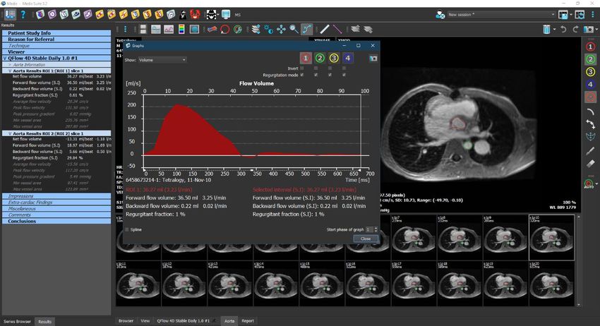
Medis Medical Imaging Systems bv
               Schuttersveld 9, 2316 XG Leiden, the Netherlands

               http://www.medis.nl

 Medis Medical Imaging Systems bv                       Medis Medical Imaging Systems, Inc.
 Schuttersveld 9, 2316 XG Leiden                        9360 Falls of Neuse Road, Suite 103
 P.O. Box 384, 2300 AJ Leiden, The Netherlands          Raleigh, NC 27615-2484, USA
 P +31 71 522 32 44                                     P +01 (919) 278 7888
 F +31 71 521 56 17                                     F +01 (919) 847 8817
 E support@medis.nl                                     E support@medis.nl

QFlow 4D 1.0 Quick Start Manual                                                               II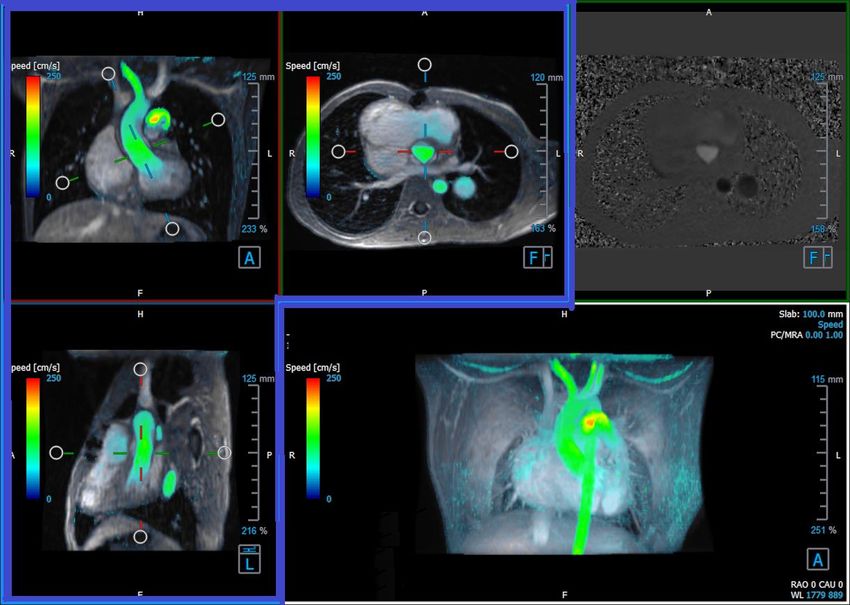
Legal Notices

Copyright Notice
© 2019 Medis Medical Imaging Systems bv. All rights reserved.

This manual is copyrighted and is protected by worldwide copyright laws and treaty provisions. No
part of this manual may be copied, reproduced, modified, published or distributed in any form or
by any means, for any purpose, without prior written permission of Medis Medical Imaging Systems
bv. Permission is granted to freely print unmodified copies of this document as a whole, provided
that copies are not made or distributed for profit or commercial advantage.

Trademark Acknowledgments
DICOM is the registered trademark of the National Electrical Manufacturers Association for its
standards publications relating to digital communications of medical information. All other brands,
product, and company names mentioned in this document are trademarks or registered trademarks
of their respective owners.

QFlow is a registered trademark of Medis Associated bv.

QFlow 4D 1.0 Quick Start Manual                                                                  III
Regulatory Information
Intended Use
QFlow 4D is software intended to be used for the visualization and analysis of MR 4D flow images of
the heart and blood vessels. QFlow 4D is intended to support the following visualization
functionalities:

    -       cine loop and 2D review
    -       double oblique review
    -       3D review by means of MIP and volume rendering
    -       3D reformatting
    -       performing caliper measurements

QFlow 4D is also intended to support the following analyses:

    -       MR velocity-encoded flow quantification

These analyses are based on contours that are either manually drawn by the clinician or trained
medical technician who is operating the software, or automatically detected by the software and
subsequently presented for review and manual editing. The results obtained are displayed on top of
the images and provided in reports.

The analysis results obtained with QFlow 4D are intended for use by cardiologists and radiologists to
support clinical decisions concerning the heart and vessels.

Indications for Use
QFlow 4D is indicated for use in clinical settings where validated and reproducible quantified
results are needed to support the visualization and analysis of MR images of the heart and blood
vessels for use on individual patients with cardiovascular disease.

When the quantified results provided by QFlow 4D are used in a clinical setting on MR images of an
individual patient, they can be used to support the clinical decisions making for the diagnosis of the
patient or the evaluation of the treatment applied. In this case, the results are explicitly not to be
regarded as the sole, irrefutable basis for clinical diagnosis, and they are only intended for use by
the responsible clinicians.

QFlow 4D 1.0 Quick Start Manual                                                                     IV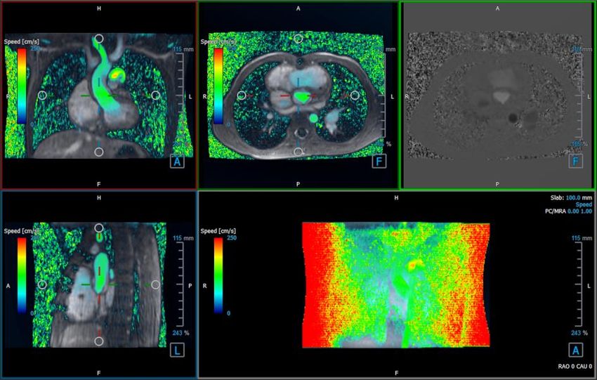
WARNINGS

    QFlow 4D must be used by cardiologists, radiologists, or trained technicians who are qualified
to perform cardiac analysis. If the analysis results are used to reach a diagnosis, the results must be
interpreted by a qualified medical professional. In clinical practice QFlow 4D should not be used for
purposes other than those indicated in the section Intended Use.

    You are explicitly recommended to measure flow parameters only in sequences that are
validated for flow measurements. Reliable measurement results can only be obtained with
validated acquisitions.

   Users must have sufficient proficiency in the English language, read this manual and become
familiar with the software and be able to obtain reliable analysis results.

Note on Monitor Aspect Ratio and Resolution

     The shapes of objects and calipers displayed may be slightly distorted when the resolution is
set to an aspect ratio different than the monitor's physical aspect ratio. This distortion does NOT
affect the accuracy of measurements or analyses. To avoid distortion, set the resolution of the
monitor to an aspect ratio equal to the physical aspect ratio. LCD monitors typically operate best at
their native resolution. Microsoft Windows recommends a resolution when it has sufficient
information to do so.

QFlow 4D 1.0 Quick Start Manual                                                                      V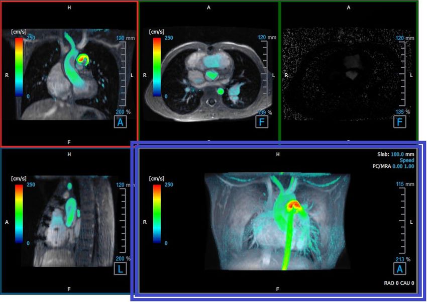
European Regulations

                   QFlow 4D is qualified as a class IIa medical device. It complies with the
                   requirements of the Dutch Medical Devices Decree (Besluit Medische
                   Hulpmiddelen, Stb. 243/1995) and the European Medical Device Directive
                   93/42/EEC.
      0120

North American Regulations
QFlow 4D has clearance for market in the United States by the FDA (Food and Drug Administration)
under the provisions of Section 510(k) of the Food, Drug, and Cosmetic Act.

Caution
Federal law restricts this device to sale by or on the order of a physician.

QFlow 4D complies with the requirements of the Canadian Medical Devices Regulations and has
been licensed as a Class II medical device.

Other Regulations
QFlow 4D complies with the requirements of the Japanese Pharmaceutical and Medical Device Law
and has been licensed as a Class II medical device.

QFlow 4D 1.0 Quick Start Manual                                                                VI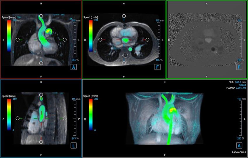
Conventions Used
The following conventions and acronyms are used throughout this manual to indicate mouse and
keyboard actions and to refer to elements in the user interface.

Mouse
Click                             Press and release the primary mouse button. If you are left-
                                  handed, you may have set the right mouse button as your
                                  primary mouse button.

Click and drag                    Press and hold the primary mouse button. Drag the mouse to
                                  perform a function. Release the primary mouse button. If you
                                  are left-handed, you may have set the right mouse button as
                                  your primary mouse button.

Right-click                       Press and release the secondary mouse button. If you are left-
                                  handed, you may have set the left mouse button as your
                                  secondary mouse button.

Middle-click                      Press and release the wheel button or the middle mouse button.
                                  If you have a two-button mouse, press and release the left and
                                  the right mouse button simultaneously.

Double-click                      Press and release the primary mouse button twice.

Wheel                             Rotate the mouse scroll wheel.

Keyboard
SHIFT/CTRL+click                  Press and hold down the SHIFT/CTRL key on your keyboard while
                                  you click a button or object.

CTRL+K                            Press and hold down the CTRL key on your keyboard while you
                                  press K, then release both keys.

Typographical Conventions

 On the Annotations node of the   Names of buttons, fields, menus, menu options, and tab names
 Results pane…                    are capitalized and in bold.

 Procedures > Text Annotation     A sequence of menu options that you select to perform a
                                  specific task is indicated by angular brackets.

 View > Movie                     A sequence of menu options that you select to perform a
                                  specific task, is indicated by angular brackets.

 Label: Flow Analysis             Text that you type or that appears on the screen, such as
                                  annotation labels, is displayed in Segou UI.

 In the Display tab, select the   Names of buttons, fields, menus, menu options, and tab names
 Hide all drawings option.        are capitalized and in bold.

QFlow 4D 1.0 Quick Start Manual                                                                    VII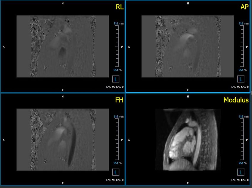
Symbols Used
                                  Reference: Points to related documentation, or to related
                                  sections in this document, that may be relevant to your
                                  situation.

                                  Tip: Provides helpful information or an alternative working
                                  method.

                                  Note: Promotes additional information.

                                  Caution: Tells you to be careful when performing a task.

                                  Warning: Warns you of a potentially dangerous situation in the
                                  image representation or analysis, which may lead to incorrect
                                  results. You are advised to follow the instructions to avoid this.

QFlow 4D 1.0 Quick Start Manual                                                                   VIII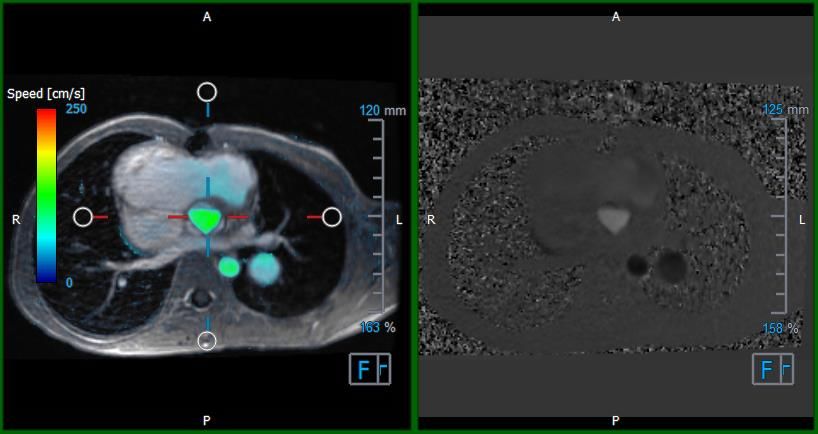
Table of Contents
Regulatory Information ............................................................................................. IV

Conventions Used ....................................................................................................VII

Typographical Conventions ........................................................................................VII

Table of Contents ................................................................................................... IX

Introduction .......................................................................................................... 12

1         About QFlow 4D........................................................................................... 12

1.1       QFlow 4D Usage........................................................................................... 12

2         System Requirements .................................................................................... 12

2.1       Hardware .................................................................................................. 12

2.2       Operating System ......................................................................................... 13

3         Support ..................................................................................................... 14

Getting Started ...................................................................................................... 15

4         The QFlow 4D Workspace ............................................................................... 15

4.1       Overview ................................................................................................... 15

4.2       Menu ........................................................................................................ 16

4.3       Toolbars .................................................................................................... 17

4.4       Workspace Panes ......................................................................................... 20

4.4.1     Results Pane ............................................................................................... 21

4.4.2     Properties Pane ........................................................................................... 22

Viewing ................................................................................................................ 23

5         Viewing ..................................................................................................... 23

5.1       Loading Series ............................................................................................. 23

5.2       Viewports .................................................................................................. 23

5.3       Viewport Layout .......................................................................................... 24

5.3.1     Verification of Flow Direction Layout ................................................................ 25

5.3.2     Flow Analysis Layout ..................................................................................... 26

5.4       Noise Removal ............................................................................................ 28

5.4.1     Noise Removal Options .................................................................................. 29

QFlow 4D 1.0 Quick Start Manual                                                                                         IX
5.4.2     Enable/Disable Noise Removal ......................................................................... 29

5.5       Viewport Overlay Type: PCMRA, Speed, Velocity .................................................. 31

5.5.1     Toggle Overlay Representation ........................................................................ 31

5.6       Frame Selection .......................................................................................... 32

5.7       Mouse Controls ............................................................................................ 33

5.7.1     Stacking .................................................................................................... 33

5.7.2     Zooming .................................................................................................... 34

5.7.3     Panning ..................................................................................................... 34

5.7.4     Window Width and Level ................................................................................ 35

5.7.5     Initial View State ......................................................................................... 36

5.8       Standard Measurements ................................................................................. 36

5.8.1     Annotations ................................................................................................ 36

5.8.2     Distance Measurements ................................................................................. 36

5.8.3     Area Measurements ...................................................................................... 37

5.8.4     Snapshots .................................................................................................. 38

QFlow 4D Analysis ................................................................................................... 39

6         Performing a QFlow 4D Analysis ....................................................................... 39

6.1       Verify Flow Velocity Directions: Overview ........................................................... 39

6.1.1     Verify All Flow Velocity Directions .................................................................... 41

6.1.2     Verify HF / FH Velocity Direction ..................................................................... 42

6.1.3     Verify AP / PA Velocity Direction...................................................................... 43

6.1.4     Verify RL / LR Velocity Direction ...................................................................... 44

6.1.5     Close the Velocity Direction Verification View ..................................................... 45

6.1.6     Custom System Options ................................................................................. 45

6.2       Background Correction .................................................................................. 45

6.2.1     Enable Background Correction ......................................................................... 46

6.2.2     Deleting Background Correction ....................................................................... 46

6.2.3     Background Correction Options ........................................................................ 46

6.3       Flow Analysis .............................................................................................. 48

6.3.1     Flow Analysis .............................................................................................. 48

QFlow 4D 1.0 Quick Start Manual                                                                                         X
6.3.2     Flow Analysis .............................................................................................. 49

6.3.3     Multiple Flow Analysis’s ................................................................................. 49

Reporting ............................................................................................................. 51

7         Sessions .................................................................................................... 51

Reference ............................................................................................................. 52

8         Shortcut Keys ............................................................................................. 52

9         General References ...................................................................................... 53

QFlow 4D 1.0 Quick Start Manual                                                                                        XI
Introduction

                                                                         Introduction

1         About QFlow 4D
QFlow 4D is the Medis software solution designed to support the 3D visualization and 2D
quantification analysis of 4D flow MR studies. It enables cardiologists, radiologists, and technicians
to quantify arterial and transvalvular blood flow.

QFlow 4D supports cardiologists, radiologists, or trained technicians, to select the appropriate
oblique views of the cardiac anatomy or surrounding vessels for quantitative flow analysis.

QFlow 4D runs as an app in the Medis Suite product. The functionality of Medis Suite, including
instructions on how to start QFlow 4D and load image data, is described in the Medis Suite user
manual. The Medis Suite documentation is available from the User documents tab, which can be
opened as follows;

    •   Press F1.

    •   Select the     help button.

    •   Select the Medis Suite main menu button in the upper right corner         > Help > User
        Documents

1.1         QFlow 4D Usage
Availability of the product QFlow 4D is dependent on licenses. If you would like to purchase a
license for one or more of the QFlow 4D applications, please contact Medis.

2         System Requirements

2.1       Hardware
QFlow 4D:
   • Intel or compatible quad-core processor
   • 16 GB of RAM
       If you are using larger image sets, particularly with multiple time points, please ensure you
       have adequate memory.
   • 250 GB of available hard disk space, SSD recommended
       (if you want to store series locally, make sure you have enough disk space)
   • 3-button mouse, scroll-wheel recommended
   • CD-ROM player to install the software from CD-ROM
   • A USB port or network connection to transfer the installer to the system
   • Video card supporting OpenGL and with 512 MB memory
   • Widescreen monitor supporting a minimum resolution of 1920x1080 pixels
   • Network interface card of at least 100MBit/s to access, receive, and send series over the
       network

QFlow 4D 1.0 User Manual                                                                            12
Introduction
Sentinel license server:
• Intel or compatible processor with a minimum speed of 550 MHz
• 128 MB of RAM
• 1 GB of available hard disk space
• Network interface card
NOTES:
• All hardware must be compliant with the operating system
• For the license server, a PC with a fixed IP address or a reserved IP address in the DNS
server is strongly recommended
2.2 Operating System
QFlow 4D:
• Microsoft Windows 7, SP1, 64 bit version
• Microsoft Windows 8.1, 64 bit version
• Microsoft Windows 10, 64 bit version
• Microsoft Windows Server 2008 R2, SP1, 64 bit version
• Microsoft Windows Server 2012 R2, 64 bit version
• Microsoft Windows Server 2016, 64 bit version
Sentinel license server:
• Microsoft Windows 7, 32 and 64 bit version
• Microsoft Windows 8, 32 and 64 bit version
• Microsoft Windows 8.1, 32 and 64 bit version
• Microsoft Windows 10, 32 and 64 bit version
• Microsoft Windows Server 2008, 32 and 64 bit version
• Microsoft Windows Server 2008 R2, 64 bit version
• Microsoft Windows Server 2012, 64 bit version
• Microsoft Windows Server 2012 R2, 64 bit version
• Microsoft Windows Server 2016, 64 bit version
QFlow 4D 1.0 Quick Start Manual 13Introduction 3 Support Medis is committed to offering high-quality products and services. If you have questions about the software, or if you would like to make suggestions for improvements in the software or in the documentation, please contact the Medis helpdesk. If you contact the Medis helpdesk by e-mail, mention the name of the software and the version number in the subject field. To look up the version number of your software, select > Help > About…. North and South America Medis Medical Imaging Systems, Inc. E-mail: support@medis.nl Telephone: +1 919 278 7888 (working days 9.00-17.00 EST) Europe, Africa, Asia and Australia Medis Medical Imaging Systems bv E-mail: support@medis.nl Telephone: +31 71 522 32 44 (working days 9.00-17.00 CET) QFlow 4D 1.0 Quick Start Manual 14
Getting Started

4         The QFlow 4D Workspace
QFlow 4D is launched from the app toolbar, app context menu, or app pane of Medis Suite, by

selecting the QFlow 4D is app icon        . Detailed information on how to start an application and
how to load series into the application, is described in the Medis Suite user manual.

This chapter covers the following topics:

    •   Overview

    •   Menu bar

    •   Toolbars

    •   Workspace panes

    •   Viewing

4.1 Overview
The main workspace consists of a menu bar, toolbars, workspace panes and the central window
area which is comprised of Double Oblique, 3D-MIP and Velocity image viewports. There are also
results and properties panes.

                                             Toolbars                                       Results

                                                           Velocity View

                                                           View
             Double Oblique View

                                                                                           Properties

                                                                     MIP

Figure 1 : Workspace Overview
                                                                     Vie
                                                                     w

QFlow 4D 1.0 User Manual                                                                              15
You can customize the workspace by hiding, resizing or moving the workspace panes and toolbars.
Any changes that you make to the workspace are saved for each individual Windows user.
4.2 Menu
The menu contains commands to activate the application functionality.
To make the menu visible:
• Select on the menu icon in the General toolbar.
The menu commands are organized into the following main menus; Panes, Toolbars, Cine, Image
Control, Procedures and Help.
In addition, there are menu items; Reset layout, Reset Window/Level, Initial View State,
Show/Hide axes and Options. For some of these commands, tool buttons are available in the
toolbars as shortcuts.
Menu commands may be grayed out when you are performing a procedure, such as an area
measurement. You can make the menu commands active by canceling or finishing the procedure.
Menu Command Description
Show or hide a workspace
Panes
pane
Toolbars Show or hide a toolbar
Cine Control the frame selection
Image Control Control the image display
Procedures Start a new procedure
Reset layout Reset the default layout
Reset the default
Reset Window/Level
window/level
Initial view state Reset the view state
Show/Hide axes Enable/Disable axes visibility
Options Application default settings
Help User documentation and About
QFlow 4D 1.0 Quick Start Manual 164.3 Toolbars
You can move toolbars to another part of the main window. You can also show or hide toolbars.
To move a toolbar:
• Click on the double-bar grip handle of the toolbar and drag it.
You can now move the toolbar to any location on the sides of the main window. Simply
click and drag the toolbar to its new position. The position of the toolbar is saved when you
close the application.
To show or hide a toolbar:
1. Select > Toolbars.
2. Select a check box to show the toolbar, clear a check box to hide the toolbar.
Or,
1. Right-click in the toolbar area. This opens a context menu.
2. Select a check box to show the toolbar, clear a check box to hide the toolbar.
The state of the toolbars is saved when you close the application.
Icon Function
General Toolbar
Show the menu
Verify flow direction.
Go to the initial view state, reset zoom \ pan \ window width \ window level
Show and Hide Axes
Remove background noise on speed overlay
QFlow 4D 1.0 Quick Start Manual 17Icon Function
Toggle image text overlay
Cine Toolbar
Go to the first frame
Go to the previous frame
Go to the next frame
Go to the last frame
Play a cine in backward direction
Stop the cine
Play a cine in forward direction
Set the cine playback speed
Mouse Controls Toolbar
Stack
Zoom
Pan
Window width and window level
Swivel (only if the 3D viewport is selected)
QFlow 4D 1.0 Quick Start Manual 18Icon Function
Procedures Toolbar
Background Correction on data
Start a flow analysis
Create a distance measurement
Create an area measurement
Create a text annotation
Create a snapshot
Copy all measurement results to the clipboard
QFlow 4D 1.0 Quick Start Manual 194.4 Workspace Panes
By default, the workspace displays the following panes to the right of the image viewports:
• Results
• Properties
You can show or hide panes, dock panes, combine panes into one tabbed panel and remove panes
from a panel.
To show or hide a pane:
• Select > Panes, and select a hidden pane to show it, or select a visible pane to hide
it.
To dock a pane:
1. Click and drag the title bar of the pane.
2. Move the pane to the sides of the viewer window to select one of the dock areas.
As the pane approaches a dock area, the area is highlighted with a dotted line. The pane
can be combined with another pane or inserted separately.
3. When the dock area of your choice appears highlighted, release the mouse button.
This docks the pane into the selected position.
To combine panes into one tabbed panel:
• Click and drag the title bar of the pane to the title bar of the pane with which you want to
combine it.
This creates a tabbed panel.
To remove panes from a panel:
• Click and drag the title bar of the pane away from the panel.
QFlow 4D 1.0 Quick Start Manual 204.4.1 Results Pane
The Results pane shows the following in QFlow 4D.
• It shows standard procedures, i.e. measurements, annotations and snapshots performed on
the series that is loaded in the viewport.
• It shows the Background Correction.
• It shows the list of Flow Analyses.
Figure 2 Results Pane
You can collapse and expand an item by selecting on the group header.
You can right-click a procedure to perform actions on the procedure. Depending on the type of
procedure, you will get a context menu with several options.
Locate: The image and the image orientation at which the procedure was
originally performed will be activated. Locate is automatically enabled
for Flow Analysis.
Rename: Rename the procedure.
Export to: Export the procedure to disk.
Export to Repository: Export the procedure to a repository.
Remove: Delete the procedure.
Flow Analysis procedures offer a list of pre-defined labels.
QFlow 4D 1.0 Quick Start Manual 214.4.2 Properties Pane
The Properties pane shows the properties of the selected procedure. You can modify QFlow 4D
standard procedures, i.e. measurements, annotations or snapshot procedures as well as the Flow
Analysis reconstructions.
To modify a label (Measurements, Annotations and Snapshots):
1. On the Results pane, select the procedure.
2. On the Properties pane, select the ellipsis on the right of the Label field and select a
predefined label, or type a custom label and press Enter.
Figure 3 Predefined Labels Menu
QFlow 4D 1.0 Quick Start Manual 22Viewing
5 Viewing
5.1 Loading Series
Series can be loaded into QFlow 4D from the Series Browser of Medis Suite. Refer to the Medis
Suite user manual for detailed instructions.
A 4D flow MRI dataset consists of time-resolved, three-dimensional series encoded in three velocity
directions and a single modulus (or magnitude) series. In QFlow4D, the three velocity orientations
are as follows
To load series from the Series Browser of Medis Suite
1. Select three sets of 4D flow velocity series and one 4D flow modulus serie, in the image or
text view of the Medis Suite Series Browser.
2. Click and drag the selected items onto any viewport.
Or,
1. Double click an item in the image view or text view of the Medis Suite Series Browser.
This will load the series into the viewports. By default, a cine will start playing to present all
individual image frames.
QFlow 4D only loads MR DICOM series.
5.2 Viewports
The viewport text overlay displays detailed information about the patient, the hospital, the image
acquisition, and the display settings.
To show or hide the patient and image information:
• Select > Options, Hangings.
Select or deselect Show patient information or Show image information.
Or
• Use ‘O’ to toggle through the different modes of hiding the overlay displays.
Or
QFlow 4D 1.0 Quick Start Manual 23• Select in the toolbar, to toggle through the different modes of hiding the overlay
displays.
To maximize an image in the viewport:
• Double-click the image.
This maximizes the viewport, so that it takes up the entire viewport.
To return to the original viewport layout, double-click the image again.
Interactive graphics are displayed in blue color and allow you to change image
or display properties with your mouse.
5.3 Viewport Layout
QFlow 4D consists of two independent screen layouts.
• Verification of Flow Direction Layout
• Flow Analysis Layout
To toggle between Flow Analysis and Verification of Flow Direction layouts
Press to toggle between Flow Analysis Layout and Verification of Flow Direction Layout.
QFlow 4D 1.0 Quick Start Manual 245.3.1 Verification of Flow Direction Layout This is the layout used for verification of the flow direction. Refer to Section: Verify Flow Velocity Directions: Overview Figure 4 Verification Of Flow Direction Layout QFlow 4D 1.0 Quick Start Manual 25
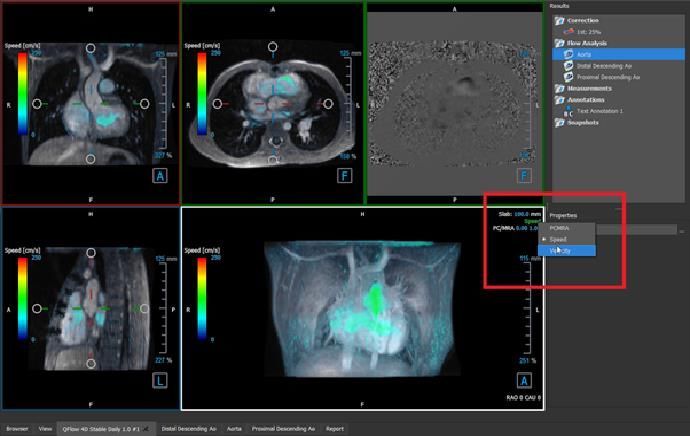
5.3.2 Flow Analysis Layout
The primary layout in QFlow 4D consists of five viewports.
1. Three double oblique views
2. 3D View
3. Velocity view
5.3.2.1 Double Oblique View
The main purpose of the double oblique views is to determine the plane of interest to be used for
Flow Analysis in QFlow 4D. The double oblique views show the orthogonal views of the 3D volume.
The double oblique viewports are highlighted in blue in Figure 5 Double Oblique Viewport Layout.
Figure 5 Double Oblique Viewport Layout
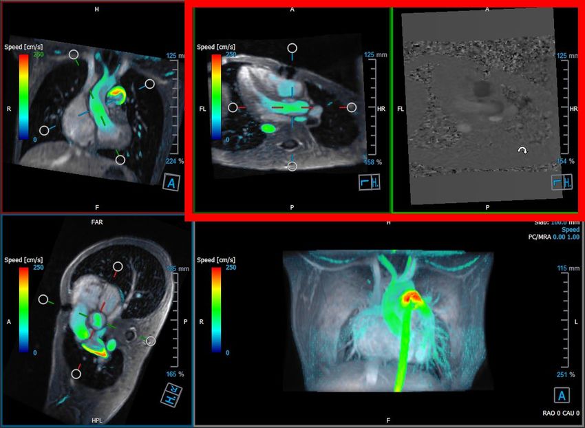
QFlow 4D 1.0 Quick Start Manual 265.3.2.2 3D View The 3D view viewport is highlighted in blue in Figure Figure 6 3D View, viewport. The 3D view is a viewport that shows the series rendered in 3D. Figure 6 3D View, viewport 5.3.2.3 Flow 2D Representation The top middle and top right viewports show the series at the reconstruction plane defined by the user for Flow Analysis procedure. The top middle viewport shows the reconstructed modulus image and the top right viewport shows the perpendicular velocities of that plane. These two planes, marked in red in Figure 6 The Modulus and Phase series, shows the data that is used for the Flow Analysis. QFlow 4D 1.0 Quick Start Manual 27
Figure 7 The Modulus and Phase images

Figure 8 Flow Analysis Plane of Modulus and Phase images

5.4 Noise Removal
QFlow 4D Noise Removal is a utility for visualization only. It is available when viewing images in
Speed mode. It filters out the air and the surrounding static tissue, essentially highlighting motion
velocity of the blood-pool. When Noise Removal is enabled, it will be automatically applied to the
three double-oblique views, as well as the 3D viewport. The velocity viewport on the top right, is
unaffected.

There are two parameters governing the behavior of the Noise Removal, the standard deviation
threshold and the modulus threshold.

QFlow 4D 1.0 Quick Start Manual                                                                     28
•   The standard deviation threshold can take values from 0-1%. It defines the static tissue to be
    removed based on the velocity of the tissue.
•   The modulus threshold can take values from 0-100% and the area to be removed based on the
    intensity of the modulus image. The area removed is based on the intensity of modulus image
    and corresponds mainly to the surrounding air and the lungs.

    QFlow 4D Noise Removal has no effect on quantification or numerical results, and it is not
applied to any data.

    Please ensure that QFlow 4D Noise Removal only removes noise from the images.

5.4.1 Noise Removal Options

To modify Noise Removal settings:

    1. Select      > Options, Noise Removal.

   Higher values, in both cases, will cause more of the speed overlay to be removed from the
image.

5.4.2 Enable/Disable Noise Removal

To enable/disable noise removal:

    1. Select         in the toolbar to enable Noise Removal.

QFlow 4D 1.0 Quick Start Manual                                                                  29
Figure 9 Noise Removal Enabled
2. Select in the toolbar to disable Noise Removal.
Figure 10 Noise Removal Disabled
QFlow 4D 1.0 Quick Start Manual 305.5 Viewport Overlay Type: PCMRA, Speed, Velocity
QFlow 4D provides multiple overlays types, each defining different visual aspects of the data.
• PCMRA
• Speed
• Velocity
5.5.1 Toggle Overlay Representation
Overlays showing speed, velocity or PCMRA may be enabled or disabled. They are visible in the
three double oblique viewports and the 3D MIP viewport.
To modify the overlay representation:
1. Select the top right-hand corner text in the 3D MIP viewport. It will toggle from
• PCMRA
• Speed
• Velocity
Figure 11 Select Overlay Type Annotation
Or,
1. Right-click the top right-hand corner text in the 3D MIP viewport. This opens a context
menu.
2. Select PCMRA, Speed or Velocity
QFlow 4D 1.0 Quick Start Manual 31Figure 12 Select Overlay Type Context Menu
5.6 Frame Selection
You can move forward or backward through the frames in the image in several ways.
Moving through frames can be done by using buttons:
• Press or on the Viewing toolbar to move to the previous or next frame.
Or,
• Press or on the Viewing toolbar to play a cine through the frames in backward or
forward direction. Click to stop the cine.
Or,
• Press or on the Viewing toolbar to move to the first or last frame.
Moving through frames can be done by using keys:
• Press the left or right arrow key to move to the previous or next frame.
Or,
QFlow 4D 1.0 Quick Start Manual 32• Press CTRL + left arrow, CTRL + right arrow to play a cine through the frames in backward
or forward direction. Press Esc to stop the cine.
Or,
• Press HOME or END to move to the first or last frame.
Moving through frames can be done by using interactive graphics:
• Select the interactive graphics for frame selection (‘Frame’) on the viewports to move to
the next frame.
Or,
• Right-click the interactive graphics for frame selection (‘Frame’) and enter the desired
frame number.
The cine speed can be modified with the slider in the Viewing toolbar.
5.7 Mouse Controls
5.7.1 Stacking
You can move through the frames using Stacking when you see the stack cursor .
To activate the stacking mouse control:
• Press in the mouse controls toolbar.
Or,
• Select Stacking from the viewport context menu.
To stack forward or backward through frames:
• Click and drag the mouse left and right or down and up to scroll through the frames. It will
loop to the first or last frame.
Or,
• Independent of the stacking mouse control status, you can scroll the mouse wheel to stack
through the frames. It will stop at the first or last frame.
QFlow 4D 1.0 Quick Start Manual 335.7.2 Zooming
You can zoom in and out of the viewport using Zooming when you see the magnify cursor .
To activate the zooming mouse control:
• Press in the mouse controls toolbar.
Or,
• Select Zooming from the viewport context menu.
To zoom in and out:
• Click and drag the mouse forward and backward to zoom in and out.
Or,
• Independent of the zooming mouse control status, you can click and drag on the interactive
zoom scale graphics, or hold Ctrl and scroll the mouse wheel up and down, to zoom in and
out.
The current zoom factor is displayed on the scale graphics in the viewport.
The value above the scale is the physical size of the scale.
The number below the scale indicates the relative zoom:
100% means one display pixel equals one acquisition pixel.
5.7.3 Panning
You can move the image within the viewport left, right, up and down using Panning when you see
the hand cursor .
To activate the panning mouse control:
• Press in the mouse controls toolbar.
Or,
• Select Panning from the viewport context menu.
To pan the image:
• Click and drag the mouse in any direction.
QFlow 4D 1.0 Quick Start Manual 34Or,
• Independent of the panning mouse control status, you can middle-click and drag the mouse
in any direction to pan the image.
5.7.4 Window Width and Level
You can adjust the window width and level (WWL) when you see the WWL cursor .
To activate the window/level mouse control:
• Press in the mouse controls toolbar.
Or,
• Select Window/Level from the viewport context menu.
To adjust the window width and level:
• Click and drag in the viewport
o Right or left to increase or decrease the width.
o Down or up to increase or decrease the level.
Or,
• Independent of the window/level mouse control status, right-click and drag
o Right or left to increase or decrease the width.
o Down or up to increase or decrease the level.
Or,
• Independent of the window/level mouse control status, click on the window width or level
interactive graphics and drag up or down to increase or decrease the window width or
level.
Or,
• Independent of the window/level mouse control status, right-click on the window width or
level interactive graphics and enter the desires values.
The current window width and level values are displayed in the lower-right overlay graphics in
the viewport.
QFlow 4D 1.0 Quick Start Manual 355.7.5 Initial View State
To reset the zooming, panning and window width and level settings to the initial view state:
• Press to reset the zooming, panning and window width and level.
5.8 Standard Measurements
QFlow 4D supports the following standard measurements:
• Annotations,
• Distance measurements,
• Area measurements,
• Snapshots.
5.8.1 Annotations
You can add annotations to a viewport to mark it for analysis or to draw attention to specific
details. Annotations are displayed in the viewport. All annotations of the active study are listed on
the Results pane.
Figure 13 Example Annotation
When you select another series or navigate to another time point in the active series, your
annotation is no longer displayed in the viewport. This is because the point to which the annotation
refers does not lie on the currently visible image. To see your annotation again, right-click on the
annotation on the Results pane and select Locate; or double-click on the annotation on the Results
pane.
For details on creating, editing and deleting annotations, see the Medis Suite User Manual.
5.8.2 Distance Measurements
A procedure to measure the distance from one point to another. When you have measured a
distance, you can modify the annotation and the end points of the measurement. All distance
QFlow 4D 1.0 Quick Start Manual 36Reference
measurements of the active study are listed on the Results pane. All distance measurements of the
active session are listed on the Results pane of Medis Suite.
Figure 14 Example Distance Measurement
When you select another series or navigate to another time point in the active series, your
distance measurement may not be displayed on the viewport. This is because the points between
which you measured do not lie on the currently visible image. To see your measurement again,
right-click on the measurement on the Results pane and select Locate; or double-click on the
measurement on the Results pane.
For details on creating, editing, and deleting distance measurements and copying the results to
clipboard, see the Medis Suite User Manual.
5.8.3 Area Measurements
You use the area measurement tool to draw and measure 2D areas. When you have measured an
area, you can modify the area contour or annotation. All area measurements of the active study are
listed on the Results pane. All area measurements of the active session are listed on the Results
pane of Medis Suite.
Figure 15 Example Area Measurement
When you select another series or navigate to another time point in the active series, your area
measurement may not be displayed on the viewport. This is because the image on which you
measured the area is not the same as the currently visible image. To see your measurement again,
right-click on the measurement on the Results pane and select Locate; or double-click on the
measurement on the Results pane.
QFlow 4D 1.0 Quick Start Manual 37Reference
For details on creating, editing, and deleting area measurements and copying the results to
clipboard, see the Medis Suite User Manual.
5.8.4 Snapshots
You can save snapshots as evidence of an analysis or diagnosis. Snapshots are displayed on the
Properties pane and are listed on the Results pane. When a snapshot is created, you can modify
the name at any time.
When you select another series or navigate to another time point in the active series, the
annotations and measurements shown in the snapshot may not be displayed on the viewport. This is
because the points at which the annotations and measurements were created do not lie on the
currently visible image. To return to the same series and time point where a snapshot was created,
right-click on the snapshot on the Results pane and select Locate; or double-click on the snapshot
on the Results pane.
For details on creating, editing and deleting snapshots, see the Medis Suite User Manual.
QFlow 4D 1.0 Quick Start Manual 38Reference
QFlow 4D Analysis
6 Performing a QFlow 4D Analysis
The Flow Analysis procedure reformats a series of time-resolved 3D volumes, into a 2D CINE series,
which can then be quantified in QFlow.
To perform a QFlow 4D flow analysis, you may use the following guidelines.
• Load series
• Visually inspect the data
Apply Noise Removal: Refer to, Noise Removal Noise Removal [5.4].
• Optional: Verify All Flow Velocity Directions
• Optional: Create a Background Correction
• Start a Flow Analysis
• Review Reporting
• Save the Session
6.1 Verify Flow Velocity Directions: Overview
A 4D flow MRI dataset consists of time-resolved, three-dimensional series encoded in three velocity
directions and a single modulus (or magnitude) series. In QFlow4D, the three velocity orientations
are as follows
• LR/RL (Left-Right/Right-Left)
• HF/FH (Head-Feet/Feet-Head) and
• AP/PA (Anterior-Posterior/Posterior- Anterior)
If velocity encoding is positive, the pixels are white and if it is negative, the pixels are black. In a
series where the data is encoded in RL direction, the areas showing the flow from right to left
would be positive and visually seen as white pixels, while areas showing the flow left to right would
be negative and seen as black.
Given that there is no standardization in the velocity encoding directions in the 4D Flow MRI field,
the directions in the data should be verified.
The user must check all orientations.
Not all Siemens and Philips scanners have 4D Flow MR acquisition protocol available for their
series. As such, the correct velocity directions cannot be warranted and therefore should be
verified.
Post processing packages may change the velocity encoding directions.
If QFlow 4D did not correctly determine the velocity encoding, contact Installation & Support for
assistance in correctly configuring your system. Refer to the Support section.
QFlow 4D 1.0 Quick Start Manual 39Reference
Figure 16 Modulus Image
H, P, A and F are indicators that assist in determining the flow direction and image orientation.
The orientation cube located at the bottom right corner can be modified to change the viewing
orientation. Refer to Figure 16 Modulus Image.
QFlow 4D 1.0 Quick Start Manual 40Reference
6.1.1 Verify All Flow Velocity Directions
To verify all velocity directions:
1. Press in the toolbar.
Figure 17 Verify Flow Velocity Direction Layout
2. Make the MODULUS viewport orientation LEFT
“L” in the square at the right bottom corner of the viewport.
3. In the MODULUS viewport, scroll through the images to find a slice including the descending
aorta and the heart chambers.
4. Determine the systolic time frame where the images have the highest velocity intensity
signal.
5. Verify HF / FH Velocity Direction
6. Verify AP / PA Velocity Direction
7. Verify RL / LR Velocity Direction
QFlow 4D 1.0 Quick Start Manual 41Reference
6.1.2 Verify HF / FH Velocity Direction
To verify the HF / FH velocity direction:
1. Press in the toolbar.
2. Make the MODULUS viewport orientation LEFT
“L” in the square at the right bottom corner of the viewport.
3. In the MODULUS viewport scroll through the images to find a slice including the descending
aorta and the heart chambers.
4. Determine the systolic time frame where the images show a definitive velocity signal.
5. Please verify at least one of the following situations described below is correct. If not,
contact Medis Support, see section: Support.
If the descending aorta is white, in the viewport containing HF / FH view, then the
velocity encoding direction should be HF.
If the descending aorta is black, in the viewport containing HF / FH view, then the
velocity encoding direction should be FH.
Figure 18 : Verify Flow Velocity Direction Layout
QFlow 4D 1.0 Quick Start Manual 42Reference
6.1.3 Verify AP / PA Velocity Direction
To verify the AP / PA velocity direction:
1. Press in the toolbar.
2. Make the MODULUS viewport orientation LEFT (“L” in the square at the right bottom corner
of the viewport.
3. In the MODULUS viewport find the aortic arch.
4. Determine the systolic time frame where the images show a definitive velocity signal.
5. Please verify at least one of the following situations described below is correct. If not,
contact Medis Support, see section: Support.
If the aortic arch is white, in the viewport containing PA / AP view, then velocity
encoding direction should be AP.
If the aortic arch is black, in the viewport containing PA / AP view, then velocity
encoding direction should be PA.
Aortic Arch is
white.
Viewed from
Left L
Figure 19 AP Positively encoded viewport, with a white aortic arch and a darker descending aorta.
QFlow 4D 1.0 Quick Start Manual 43Reference
6.1.4 Verify RL / LR Velocity Direction
To verify the AP / PA velocity direction:
1. Press in the toolbar.
2. Make the MODULUS viewport orientation ANTERIOR
“A” in the square at the right bottom corner of the viewport.
3. In the MODULUS viewport find the slice including the ascending aorta.
4. Determine the systolic time frame where the images show a definitive velocity signal.
5. Please verify at least one of the following situations described below is correct. If not,
contact Medis Support, see section: Support.
In the viewport containing RL / LR view, the orientation is LR if the proximal ascending
aorta is white and the distal ascending aorta is black.
In the viewport containing RL / LR view, the orientation is RL, if the proximal ascending
aorta is black and the distal ascending aorta is white.
Distal
ascending
aorta
Proximal
ascending
aorta
Figure 20 RL Positively encoded viewport, with proximal and distal ascending aorta
QFlow 4D 1.0 Quick Start Manual 44Reference
6.1.5 Close the Velocity Direction Verification View
1. Press in the toolbar. The layout will return the QFlow 4D analysis layout.
6.1.6 Custom System Options
Medis Installation & Support may provide a new System options file with different settings, which
will correct the velocity direction view.
To apply I&S custom system options.
1. Re-open the dataset in QFlow4D and press to open the correction layout.
2. Press to correct the series orientations with the new settings.
6.2 Background Correction
The quality of the phase velocity data may be compromised as a result of background phase
distortions. These distortions can be corrected by applying a stationary flow fit algorithm to the
data. The Background correction utility is a quantitative tool which removes phase offset errors
from the data, thereby correcting phase offset errors.
The background correction which is also known as stationary flow fit algorithm, has two
configurable settings, the Standard Deviation Threshold to define the static tissue mask and the
Fitting order which defines the level of complexity of the fitting.
Standard Deviation Threshold.
A low standard deviation threshold value might cause inclusion of insuffient static tissue
volume to obtain an accurate background correction
A high standard deviation threshold value might cause inclusion of flow area as static tissue
which would result in an inaccurate background correction.
25% standard deviation threshold is the default.
Fitting order
The fitting order of the stationary flow fit algorithm defines the complexity of the fitting
planes used to correct the phase offset error. There are three fitting orders, 1st 2nd and 3rd,
which in theory, respectively produce more sophisticated background corrections, although
they require longer computational time.
The Background Correction settings are used for all Reconstructions and they are published in the
Results pane, the Report tab in Medis Suite.
The background correction affects the reconstruction procedure(s). When a background
correction is modified or completed, all existing reconstructions in the current session, will be
updated to use the new background corrected data.
QFlow 4D 1.0 Quick Start Manual 45Reference
Noise Removal has no effect on background correction.
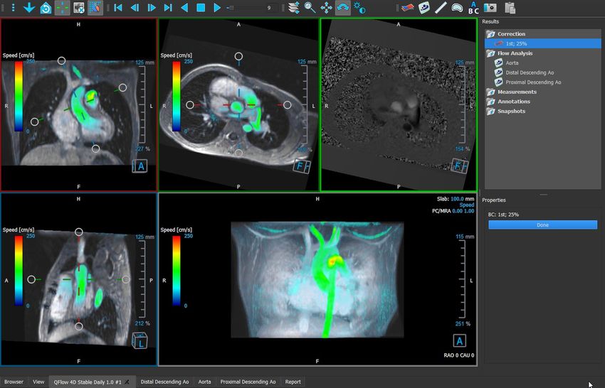
6.2.1 Enable Background Correction
To enable background correction.
1. Press in the toolbar.
The Properties pane of the Background
Correction displays the following;
• Background Correction progress
• The selected threshold
• The selected fitting order
• Cancel button, to cancel the correction
Background Corrections are individually activated by clicking the Correction in the Results pane.
Once selected, the corresponding Properties pane is shown.
From the Properties pane each background correction can be located, deleted and renamed. The
Properties pane shows Background Correction options and progress.
Any changes to Background Corrections threshold or fitting order are applied to all
reconstructions in the current session.
6.2.2 Deleting Background Correction
You can delete any Background Correction that was created.
To delete a Background Correction:
1. Select the Background Correction in the Corrections list on the Results pane.
2. Press Delete on your keyboard or right-click and select Remove.
This deletes the Background Correction.
6.2.3 Background Correction Options
You can change and apply the Background Correction settings using the options menu.
To modify Background Correction settings:
2. Select > Options, Background Correction.
• The Std Threshold can be modified with the slider .
QFlow 4D 1.0 Quick Start Manual 46Reference
• The Stationary Flow Fit, Fitting Order can be selected.
Any changes to Background Corrections threshold or fitting order are applied to all
reconstructions in the current session.
QFlow 4D 1.0 Quick Start Manual 47Reference
6.3 Flow Analysis
The QFlow 4D Flow analysis is referred to as a Reconstruction. The Flow Analysis procedure
enables reformatting the time-based 3D volume, into a 2D series, which is then quantified in
another app, QFlow 2D.
These are the steps to complete a Flow analysis.
1. Locate the plane of interest. Refer to Double Oblique View.
2. Start a Flow analysis
• Optionally: Rename the reconstruction
3. Complete a Flow analysis
4. Rename the Flow analysis label, from “Reconstruction” to an appropriate label.
All Flow Analyses results are stored in the QFlow 4D results, reports and session.
Multiple Flow analyses may be started.
The flow analysis in QFlow 4D is performed in a separate tab outside QFlow 4D using the
existing QFlow application.
6.3.1 Start Flow Analysis
QFlow 4D supports locating, renaming, exporting and removing of the flow analyses. Flow Analysis
is labelled by default “Reconstruction”.
To start a flow analysis
• Select from the toolbar.
Or,
3. Right-click in the viewport area. This opens a context menu.
4. Select Flow Analysis
QFlow 4D 1.0 Quick Start Manual 48Reference
6.3.2 Flow Analysis App
Flow analysis will be started with the QFlow 4D reformatted dataset.
• Press F1.
• Pushing the help button.
• Select the Medis Suite main menu button in the upper right corner > Help > User
Documents. For detailed instructions on using Flow 2D, refer to the QFlow 2D User manual.
Figure 21 QFlow2D hosting the Flow analysis
6.3.3 Multiple Flow Analysis’s
QFlow 4D supports multiple Flow analyses. Each new Flow analysis creates a new tab.
Figure 22 Results Pane with multiple flow analysis
QFlow 4D 1.0 Quick Start Manual 49Reference Figure 23 List of multipe tabs, each with a flow analysis QFlow 4D 1.0 Quick Start Manual 50
Reference

          Reporting
QFlow 4D results are made available in the Medis Suite Results pane and in the Medis Suite report.

Figure 24 Medis Suite Report with QFlow 4D Results

The Reporting functionality of Medis Suite is described in the Medis Suite user manual. The Medis
Suite documentation is available from the User documents tab, which can be opened as follows;

    •   Press F1.

    •   Pushing the       help button.

    •   Select the Medis Suite main menu button in the upper right corner        > Help > User
        Documents

7         Sessions
The QFlow 4D state can be saved in a Medis Suite session. The session can be reloaded to continue
or review the analyses.

The session functionality in Medis Suite is described in the Medis Suite user manual. The Medis Suite
documentation is available from the User documents tab, which can be opened as follows;

    •   Press F1.

    •   Pushing the       help button.

    •   Select the Medis Suite main menu button in the upper right corner        > Help > User
        Documents

QFlow 4D 1.0 Quick Start Manual                                                                     51
Reference
Reference
8 Shortcut Keys
When you are working with QFlow 4D, you can use several combinations of keys on your keyboard
and mouse actions to quickly perform the following tasks.
Press To
Layout
F11 Show or hide the workspace window panes
Image control
Middle-click and hold Hide all graphics
Middle-click and drag, or Pan
Ctrl and drag
Ctrl+Shift and drag Zoom
Alt+Shift and drag Stack
Procedures
A Create an area measurement
D Create a distance measurement
S, or Create a snapshot
CTRL+SPACE
Esc Stop editing the procedure
Delete Delete the currently selected procedure
QFlow 4D 1.0 Quick Start Manual 52Reference Press To SHIFT+Delete Delete all procedures Navigation Controls HOME Display the first time point END Display the last time point Arrow up Display the previous slice Arrow down Display the next slice Arrow left Display the previous time point Arrow right Display the next time point CTRL+arrow left Play cine backward CTRL+arrow right Play cine forward Esc Stop playing cine Page Up Display the previous series Page Down Display the next series 9 General References Anterior (or ventral) Describes the front or direction toward the front of the body. The toes are anterior to the foot. Posterior (or dorsal) Describes the back or direction toward the back of the body. The popliteus is posterior to the patella. QFlow 4D 1.0 Quick Start Manual 53
You can also read