User Manual for Conventional Press Brakes - Sept. 2019 V2.1 - Cybelec
←
→
Page content transcription
If your browser does not render page correctly, please read the page content below
®

                                Sept.
     User Manual                2019
for Conventional Press Brakes   V2.1
© 2019 Cybelec S.A.
                                        All Rights Reserved
Copying, reproduction, modification, distribution, display or transmission of any of the contents of
   this manual for any purpose without the prior consent of Cybelec S.A. is strictly prohibited.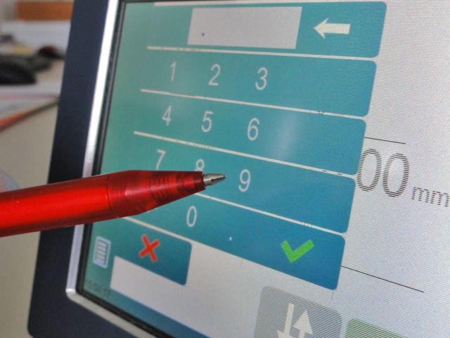
The Intuitive Programming                                                                                                                                      ®

                                                       Table of content
Safety.......................................................................................................................1
   General Safety................................................................................................................................ 1

   Signs and Icons appearing in this Manual................................................................................... 2

       General warning.............................................................................................................................. 2

       Information.................................................................................................................................... 2

       Settings........................................................................................................................................... 2

       Navigation..................................................................................................................................... 2

Getting started with CybTouch 8 P ..........................................................................3
   General navigation........................................................................................................................ 4

       Menu Button ................................................................................................................................. 4

       Status Pages Zone............................................................................................................................ 4

       Screen Cleaning............................................................................................................................... 4

   Status page..................................................................................................................................... 5

   User Preferences........................................................................................................................... 5

       Language....................................................................................................................................... 6

       Length Units................................................................................................................................... 6

       Force Units...................................................................................................................................... 6

       Sigma Units.................................................................................................................................... 6

       Show axes position values.................................................................................................................. 6

       RFLink........................................................................................................................................... 7

       Clear indexation.............................................................................................................................. 7

       Set Clock......................................................................................................................................... 7

       Touchscreen Calibration.................................................................................................................... 7

       Brightness xx% Eco xx%................................................................................................................. 7

       Program counter mode...................................................................................................................... 8

   Manual Axes Movement................................................................................................................ 9

       In the Program or EasyBend page....................................................................................................... 9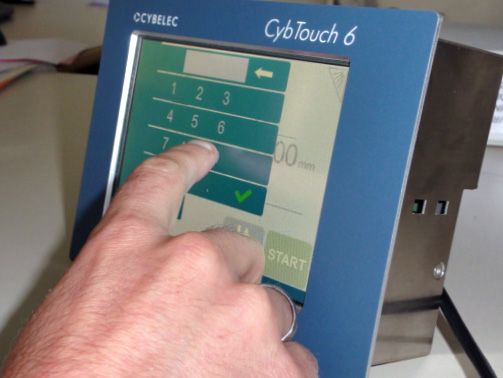
®                                                                                              The Intuitive Programming

       In the Manual Movement page.........................................................................................................10

   Service Page................................................................................................................................. 11

       Set Axis.........................................................................................................................................11

       Maintenance..................................................................................................................................11

       Information...................................................................................................................................12

           Defrag............................................................................................................................................................... 12

           Format.............................................................................................................................................................. 12

           Internal backup............................................................................................................................................... 12

       Configuration options......................................................................................................................13

           Serial number.................................................................................................................................................. 13

           Computer ID.................................................................................................................................................... 13

           Option list........................................................................................................................................................ 13

           New option code.............................................................................................................................................. 13

Basic Page Description........................................................................................... 14
   Bend Numerical Page................................................................................................................. 14

       Available functions on the Bend Num page.........................................................................................14

           Current step (sequence) number................................................................................................................... 14

   More Page.................................................................................................................................... 15

       Available functions on the More page.................................................................................................15

           Tooling management...................................................................................................................................... 15

           Back gauge retraction..................................................................................................................................... 15

           Force................................................................................................................................................................. 15

           Opening (TDC)............................................................................................................................................... 16

           Step bending.................................................................................................................................................... 16

           Dwell time........................................................................................................................................................ 16

           Number of parts.............................................................................................................................................. 16

           Back gauge manual control............................................................................................................................ 17

           Material thickness............................................................................................................................................ 17

           Material sigma.................................................................................................................................................. 17

   Copy to All Function................................................................................................................... 18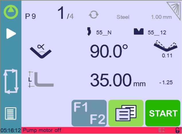
The Intuitive Programming                                                                                                                                      ®

Tools Management................................................................................................. 19
   Punches........................................................................................................................................ 19

       How to create or modify a punch?......................................................................................................19

   Dies............................................................................................................................................... 20

       How to create or modify a die?...........................................................................................................21

   Naming Tools............................................................................................................................... 22

       Punches.........................................................................................................................................22

       Dies...............................................................................................................................................22

Creating a Part Program......................................................................................... 23
   Bending with Tools Management............................................................................................... 23

   Bending and Corrections............................................................................................................ 24

       Semi-Automatic mode.......................................................................................................................25

       Angle Correction.............................................................................................................................25

       Back gauge Correction.....................................................................................................................25

   Bending without Tools Management......................................................................................... 26

   Next-Part Function...................................................................................................................... 27

       Cycles and quantities.......................................................................................................................28

Saving and Loading a Program............................................................................... 29
   Saving a Program......................................................................................................................... 29

   Loading a Program..................................................................................................................... 29

   Deleting a Program..................................................................................................................... 29

EasyBend Page....................................................................................................... 30
   Making a bend on the EasyBend Page....................................................................................... 30

Error and Warning Messages.................................................................................. 31
   Warning Messages....................................................................................................................... 31

   Error Messages............................................................................................................................. 34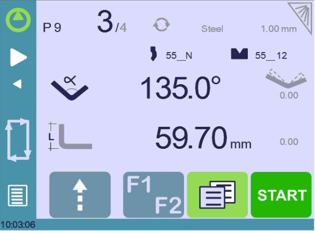
® The Intuitive Programming
CybTouch 8 P User Manual

Safety

General Safety
                    The users must have Read and Understood, but most of all must Respect the
                    directives described in this manual.
                    All people coming into contact with the machine on which the numerical
                    control is installed, whatever their function or whatever state the machine is in
                    (assembly, disassembly, start-up, production, maintenance, repairs) must have
                    read and understood the requirements concerning the security and the entirety
                    of the directives of operation described in the manuals delivered with the
                    machine.

                    The operator must be properly trained to work with the machine
                    on which the numerical control is installed. Improper use of the
                    numerical control can cause heavy damage on equipment and/or
                    injuries to people.

                    Modification of machine parameters can cause important material damage or
                    lead to irregular product quality.
                    Do not expose the numerical control to excessive humidity so as to avoid any
                    risk of electrocution and any deterioration of the equipment.
                    Make sure the numerical control is disconnected from the mains power before
                    carrying out any cleaning. Do not use liquids based on alcohol or ammoniac.
                    In case of malfunction of the numerical control, call a technician.
                    Do not expose the numerical control to direct sun rays or any other heat source.
                    Do not place the numerical control in the neighborhood of magnetic equipment
                    such as transformers, motors or devices which generate interference (welding
                    machines, etc.).

                                                                                            Sep.
                                                                                            2019   1/38
                                                                                            V2.1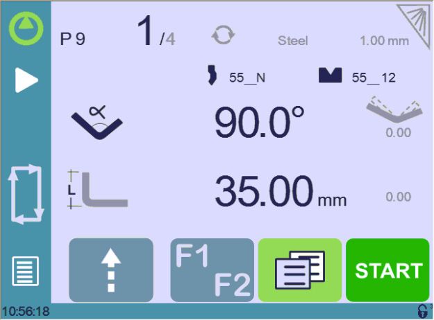
®                                                                 CybTouch 8 P User Manual

Signs and Icons appearing in this M anual
                  While using this manual, you will come across the signs and icons represented here
                  below: they are directly related to the safety and security of persons. Carefully follow this
                  advice and inform others about it.

General warning   This warning sign appears in the manual whenever it is necessary to pay attention to
                  rules, instructions or advice. The correct sequence of operations is to be followed in order
                  to avoid damage to the machine.
                  Symbolizes a serious personnel danger

Information       This warning sign appears in this manual whenever an important information needs to be
                  taken into consideration. Pay attention to this sign and follow the instructions given.

Settings          This sign appears in this manual whenever setting instructions are given. Pay attention to
                  this sign and follow the sequence of instructions given.

Navigation        This icon appears in this manual to give navigation information, to give the path to the
                  subject treated in the chapter.

       Sep.
2/38   2019
       V2.1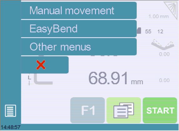
CybTouch 8 P User Manual

Getting started with CybTouch 8 P
                    Depending on software evolutions and the press brake controlled by the CybTouch
                    (configuration/capabilities), the present manual may not fully correspond to the CybTouch
                    that you currently have. However, differences are only minor.

                    Touchscreens are pressure sensitive. Do not press down hard on the
                    screen.
                    Pressing hard on the screen will damage the display. Such damage is
                    not covered by manufacturer warranty!

                    Do not use sharp and/or pointed objects (sheet metal, screwdriver,
                    metal pen ball, etc.) to touch the screen.

                    Only use your fingers (with or without gloves on) or a plastic pen. Make sure that your
                    gloves do not have metal particles encrusted in the finger tips as they may also damage
                    the screen.
                    Take a few minutes to practice pressing gently on the screen, you will find that the screen
                    is very reactive and it is pleasant to use.

                                                                                                     Sep.
                                                                                                     2019   3/38
                                                                                                     V2.1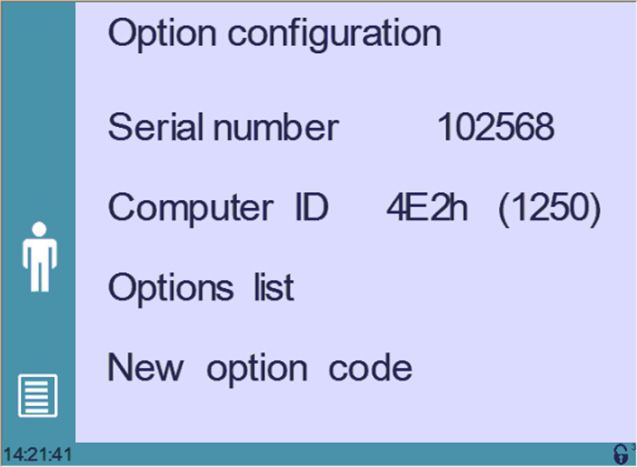
®                                                              CybTouch 8 P User Manual

General navigation

                                  Add step                                                  Screen Cleaning button
                               or next step

                          Status Pages Zone

                              Menu Button

Menu Button           The Menu button     allows you to directly select (jump to) the desired screen. The
                      content of the menu changes contextually.

Status Pages Zone The Status pages zone gives access to the Status page (see page 5). This is really a
                      zone that is active at any moment from any page (except the wizard’s).

Screen Cleaning       To clean the screen while the CybTouch is on, touch the    button.
                      Use only a damp and smooth cloth with soap or a neutral detergent.

                      NEVER use solvent, petrol, benzene, alcohols, etc.

        Sep.
 4/38   2019
        V2.1
CybTouch 8 P User Manual
Status page
The Status page shows the status of all inputs and outputs and axes positions of the NC.
This feature is very useful during setup or during phone service with a machine installed in
the field.
This page is accessed from anywhere by pressing the Status Pages Zone (see page 4).
To exit the Status page, press on the arrow on the left.
On the upper line, a cycle
Press arrow to message may appear
exit Status Page indicating the cycle phase
the machine is executing
User Preferences
(Menu Button) → Other menus → User preference
To exit the User Preference page, touch the button.
Sep.
2019 5/38
V2.1® CybTouch 8 P User Manual
Language To browse through the available languages, simply touch Language on the screen.
Available languages are:
• EN English. • FR Français. • RU Pусский.
• CN 中文. • IT Italiano. • TR Türkçe.
• CZ Český. • NL Nederlands. • TW 台灣.
• DE Deutsch. • PL Polski.
• ES Español. • PT Português.
The list of available languages is subject to change and may increase over time.
Length Units This parameter allows choosing between mm, inch and none for the length unit to be
used in the CybTouch.
When none is selected, the units used are millimeters.
Force Units This parameter allows choosing between ton, kN and tons for the force unit to be used in
the CybTouch.
Sigma Units This parameter allows choosing between kg/mm2, N/mm2 and psi(*1000) for the sigma
unit to be used in the CybTouch.
Show axes This function will display the axes positions on the Bend Numerical Page (see page 14).
position values • When set to no, the positions of the axes are displayed during the respective
movements.
• When set to yes, the positions of the axes are constantly displayed under their
respective set-point values.
Sep.
6/38 2019
V2.1CybTouch 8 P User Manual
RFLink When activated, this function allows communication between the CybTouch and a laptop
computer, onto which Cybelec’s RFLink dongle is plugged in. This function’s default status
is off, and it is automatically reset to off every time the NC is turned on.
Clear indexation When activated, this function clears the index and the machine will search for them, as
it does when turning the power on, allowing the operator to re-index its machine without
turning it off.
Set Clock Allows the user to set the time and date on the CybTouch.
Touch the field you Use the up and down
want to modify arrows to modify the
selected field
Touchscreen As a tall operator will tend to touch higher than a smaller one on the screen, this function
Calibration allows the calibration of the touch screen, and also makes sure that it is operating
correctly.
Setting Instructions:
Simply follow the instructions on the page to calibrate the touchscreen.
Use your finger or the plastic tip of a pen to calibrate the
Touchscreen. Never use sharp objects as this will damage the screen.
Brightness xx% Here the brightness of the screen for normal mode and Eco mode can be defined:
Eco xx% 1. Touch the mode for which you want to modify the brightness.
2. Use the buttons to set the brightness.
Sep.
2019 7/38
V2.1® CybTouch 8 P User Manual
Program counter This parameter allows defining the counting mode of the part counter. When set to up,
mode the counter will count up to the desired number. When set to down, the counter will
count from the desired number down to 0.
Materials Touching Materials opens the Materials page, where the default characteristics for each
material can be changed, or a new material can be configured.
This page may not be available, depending on the machine parameters’
configuration. To be allowed to access the Materials page, a level 2 password is
required.
The Materials page displays:
• Material: Selected material (here Steel).
• Default thickness for the material.
• Default sigma: Default sigma for the material (here 45).
• Displayed: If the material will be available to be selected for use (here yes).
• Predefined thickn.: Allows defining up to 7 different predefined thicknesses for the
selected material.
• Thickness min/max: determines the maximum and minimum accepted thickness for
the selected material.
Three predefined default materials are available (steel, stainless steel, aluminum), but
others can be added.
To add a material:
1. Touch Material and select a non-configured material (Mater X) from the list.
2. Enter the new material’s characteristics.
3. Touch the name (Mater X) to display the keyboard and enter the name of the new
material.
Sep.
8/38 2019
V2.1CybTouch 8 P User Manual
M anual A xes Movement
In the course of setting up a machine, it is sometimes necessary to be able to move
the axes manually, for example when changing the tooling. This can be done from two
different places:
• In the Program or EasyBend page.
• In the Manual Movement page.
In the Program or In the Program or EasyBend page, axes can be moved manually only when the tool
EasyBend page management is deactivated.
Select the axis you want
to move manually by Use these arrows to move
touching its icon the selected axis manually
Setting Instructions:
1. Touch the button and then touch the icon (if available); it will become gray.
2. Touch the button to come back to the program page.
3. Touch the Y axis icon and use the manual buttons ( and ) to move it.
4. Proceed in the same manner to move the back gauge axis.
Sep.
2019 9/38
V2.1® CybTouch 8 P User Manual
In the Manual The manual movements also have their dedicated page, which can be accessed following
Movement page the link below.
(Menu Button) → Manual movement
Move beam up
(button hidden if
movement not allowed)
Menu Button
Setting Instructions:
1. Select the axis that you want to move:
• for the back gauge X axis.
• for the back gauge R axis.
2. Touch the buttons to move the selected axis.
3. Use the foot switch (Low Speed Down movement) and this button (High Speed
Up) to move the beam.
Sep.
10/38 2019
V2.1CybTouch 8 P User Manual
Service Page
(Menu Button) → Other menus → Service → Service
Set Axis Allows the operator to manually adjust the position of the back gauge (axis X) and the
beam (axis Y, if available).
This function must be used with utter care and only by experienced
personnel. Wrong settings may mechanically damage the machine.
Settings are lost after indexing the machine.
Maintenance The Maintenance page displays the hardware status of the CybTouch and lets the
operator perform different maintenance actions.
(Menu Button) → Other menus → Service → Service → Maintenance
All the following actions require codes and should only be performed by
technicians or upon request of a technician.
Sep.
2019 11/38
V2.1® CybTouch 8 P User Manual
Defrag
This function will rearrange the memory space of the CybTouch. Simply touch it and
follow the instructions given in the yellow pop-up window.
Format
This function will erase all data in the CybTouch. Only use this with the help of a
technician.
Internal backup
This function is specially designed for OEM and support.
Usually a machine parameters’ backup is made by the machine manufacturer or the
company who services the machine. This backup allows a maintenance technician to
restore original working parameters if necessary.
Should there be a need to restore parameters, call on a maintenance technician and
follow his instructions.
Do not try to use this function unless you are in dire need.
Before using this last function, make sure that all your files have
been transfered outside the CybTouch (using CybTouchTools, see the
relevant Instructions manual).
Information The Information page displays the names and versions of the softwares installed on the
CybTouch. Pressing the Advanced button shows more detailed information.
(Menu Button) → Other menus → Service → Service → Information
To Advanced information
Sep.
12/38 2019
V2.1CybTouch 8 P User Manual
Configuration Touching this menu opens the following page, where one can find the computer’s
options identification and manage the machine’s options.
(Menu Button) → Other menus → Service → Service → Configuration options
Serial number
This is the serial number of the CybTouch. It is entered at the factory at the end of the
machine’s initial setup and is related to the machine’s option list.
Changing the serial number means that all the options installed on the
machine can be lost.
Computer ID
This line displays an identification code that is unique to each CybTouch and guarantees,
together with the serial number, a correct identification of the machine.
Option list
This function opens a yellow pop-up window where all the options installed on the
CybTouch are displayed.
New option code
The function opens an alphanumerical pad where the code of the new option must be
entered. The format of an option code is: ABC-DEF-GHI-JKLM
Sep.
2019 13/38
V2.1® CybTouch 8 P User Manual
Basic Page Description
Bend Numerical Page
Current step (sequence) number Repeat sequence button
(inactive here)
Pump button Current cycle activity information
(if configured)
Material
Program number
Material thickness
Add step or next step
Tools Management
Beam (Y axis) position Bending and Corrections
value / bend angle
Back gauge Correction
Back gauge (X axis)
position / flange length More Page
Menu Button Start – Stop
Interactive message line Auxiliary function button
Available The Bend Numerical Page is normally the working page, from which the bends are
functions on the executed, and most of the navigation originates from and leads to.
Bend Num page
Current step (sequence) number Insert step here
Delete current step here
Touching the step number will open a
Go to selected step here
yellow pop-up window as shown here, with
3 different actions to choose from:
Select the step to jump
• Insert step: this function will insert a to here
step after the current one.
• Delete step: this function will erase the
current step.
• Go to step: this function allows jumping
directly to the desired step.
Sep.
14/38 2019
V2.1CybTouch 8 P User Manual
More Page
Bend Numerical Page →
Material thickness Material sigma
Material Tooling management
Next step Bending length
Back gauge retraction Step bending
Crowning
Force
Return to Bend
Opening (TDC) Numerical Page
Dwell time Access to more functions
Available The More page displays parameters related to the part, and depending on the CybTouch
functions on the configuration and the type of action performed, it also displays various settings for the
current bend.
More page
Tooling management
When deactivated (grayed), this icon disables the Punches (see page 19) icon and
the Dies (see page 20) icon from the Bend Numerical Page (see page 14) (see also
Bending without Tools Management, page 26).
Back gauge retraction
The back gauge retraction can be activated/deactivated using this icon. It is possible to
modify the value by touching it. This is a sequence parameter, meaning it can be modified
with each step of the program.
Force
The force is automatically calculated by the CybTouch, according to the Material, the
Material thickness, the Material sigma and the Bending length. The value can also be
manually modified here.
Sep.
2019 15/38
V2.1® CybTouch 8 P User Manual
Opening (TDC)
When activated, this parameter allows defining the duration during which the beam
moves back up from BDC. This value must be set to allow the operator enough room to
extract its bent part from between the tools.
When this field is deactivated (grayed), the beam moves back all the way up to
its maximum limit switch.
Step bending
Activating this field allows programming a
large radius bend, by entering the value of
8
αb α a
the radius and in how many steps we want
7
S
to make it.
S ½
αc
6
S
For the result to be coherent, the
αc
S
number of bends to realize the angle
5
S
must be such that the length of each ½S S
c
α
segment is greater than half the length αc
4
of the V opening of the die. αa α b
3
1 2
Dwell time
Allows defining the duration of the dwell time, meaning the time during which the punch
remains at BDC before coming back up.
When this field is deactivated (grayed), the default Dwell Time value defined in
the machine parameters is applied.
Number of parts
The operator can enter here the total amount of parts to be produced. Every time all
the sequences of the program are executed, hence a part is completed, this counter is
updated of one unit (increased or decreased, see Program counter mode, page 8).
When the amount of parts is reached, a yellow pop-up window signals it to the operator.
Sep.
16/38 2019
V2.1CybTouch 8 P User Manual
Back gauge manual control
Activating this parameter gives manual control over the back gauge movement. This
means the operator must personally give the start to the back gauge movement, using for
example the foot switch or the start button.
Bending length
This parameter defines the width of the sheet metal part that will be pinched between the
tools. It is used to calculate the bending force.
If this parameter is not activated (gray), the CybTouch will not calculate the
bending Force and the Crowning.
Material
This is not a sequence parameter, but of course a part parameter. Each touch on the
material’s name selects the next available from the list of Materials (see page 8).
Material thickness
Predefined thicknesses
The default thickness, defined in Materials
(see page 8), is automatically displayed
when changing material. It is however
possible to change it simply by touching
this icon.
Touch here to manually
If on the other hand, the parameter insert a thickness
Predefined thickn. (see page 8) is set
to yes, a touch on this icon will open a
numerical pad as show to the right, where
the operator will be able to select directly
one of the predefined thicknesses.
This is a part parameter.
Sep.
2019 17/38
V2.1® CybTouch 8 P User Manual
Material sigma
The default sigma, defined in Materials (see page 8), is automatically displayed when
changing material. It is however possible to change it simply by touching this icon. This is
also of course a part parameter.
Crowning
The crowning function is activated here. It is automatically calculated, according to the
Material, the Material thickness, the Material sigma and the Bending length.
The value can be manually changed by operator. It will however be automatically
recalculated if any of the values used for its calculation is changed.
The mechanical crowning system can only move when the beam is at TDC.
When the crowning function is deactivated (gray icon), the crowning system
physically remains to its last position and does not automatically return to
0.0 mm. Keep that in mind when using this function – or not – between one
sequence and the following.
Copy to A ll Function
This function allows copying a defined
value to all the steps of the current
program. It appears in the numerical pad of
relevant fields, such as Force, Bending and Copy to all button
Corrections, etc.
Sep.
18/38 2019
V2.1CybTouch 8 P User Manual
Tools Management
Tools management allows the creation and configuration on the CybTouch of the tools to
be used on the machine. These tools are then taken into account in bend calculations.
Depending on the CybTouch version and the press brake configuration, punch
and die management may not be available on the CybTouch you have.
Punches
Bend Numerical Page →
Punch name
Types of punches
Browsing through
existing punches
Punch mounting direction
Basic punch data
Return to Bend
Numerical Page
Setting Instructions:
To select a punch, simply browse through the existing punches in your library using the
arrows buttons, and then return to Bend Numerical Page.
How to create or If no punch is yet created, the punch will have no name (??? is displayed). If a punch
modify a punch? already exists, then the last punch used will be selected, here 55_N (modifications will
not alter the existing punch as they will be saved under another name).
1. Touch the button and then touch the icon to activate tool management if
necessary.
2. Touch the punch icon to access the punch details.
3. Enter the characteristics (α (punch angle), Height and Radius) for the new punch to
be created.
4. Select the punch type (straight, normal or gooseneck) with this icon . This
characteristic is only an information for the operator.
Sep.
2019 19/38
V2.1® CybTouch 8 P User Manual
5. Touch the button to invert the punch if necessary.
To be allowed to save a tool, a level 2 password is required.
6. Touch the punch name (here 55_N).
7. Touch Save punch to overwrite the existing tool or Save punch as if you want to
save your tool under another name.
8. Enter the name of the new punch using the alphanumerical keypad.
We recommend that you follow the naming conventions explained in Naming
Tools (see page 22).
9. Touching the button brings you back to the program page, with the punch you
just saved being selected and ready to be used.
Dies
Bend Numerical Page →
Die name Die mounting direction
Browsing through
existing dies
Basic die data
Return to Bend
Numerical Page
Setting Instructions:
Selecting a die is the same as selecting a punch; simply browse through the existing dies
in your library using the arrows buttons, and then return to Bend Numerical Page.
Sep.
20/38 2019
V2.1CybTouch 8 P User Manual
How to create or If no die is yet created, the die will have no name (??? is displayed). If a die already exists,
modify a die? then the last one used will be selected, here 55_12 (modifications will not alter the
existing die as they will be saved under another name).
Ve
1. Touch the button and then
touch the icon to activate tool
management if necessary. R
2. Touch the die icon to access the
die details.
3. Enter the characteristics (Ve (die
width), α, Height, Radius and Safety
XS) for the new die to be created.
Safety XS defines the security distance between the tool and the back gauge for
X axis.
4. Touch the button to invert the die if necessary.
To be allowed to save a tool, a level 2 password is required.
5. Touch the die name (here 55-12).
6. Touch Save die to overwrite the existing tool or Save die as if you want to save your
tool under another name.
7. Enter the name of the new die using the alphanumerical keypad.
We recommend that you follow the naming conventions explained in Naming
Tools (see page 22).
8. Touching the button brings you back to the program page, with the die you just
saved being selected and ready to be used.
Sep.
2019 21/38
V2.1® CybTouch 8 P User Manual
Naming Tools
It is recommended that you use naming conventions for your tools.
Below you will find a simple convention allowing you to precisely identify a punch or die
through its name.
Of course, depending on your needs you may need to create more rules for punch and die
naming.
Punches The name of the punch should be built in the following manner: first its angle, followed by
its type, and then whether it is inverted or not.
Punch angle (°) Punch type Inverted or not
30 N = Normal
60 _ S = Straight _ i = If inverted
90 G = Gooseneck
Following these rules, here are some examples of punch names: 90_N_i, 60_G, 30_S,
and so on, and so forth.
Dies The name of the die should be built in pretty much the same manner: first its width (Ve
dimension), followed by its angle, and then whether it is inverted or not.
Ve (mm) Die angle (°) Inverted or not
12
30
16 _ _ i = If inverted
86
20
Following these rules, here are some examples of die names: 12_86_i, 16_86, 20_30,
and so on, and so forth.
Sep.
22/38 2019
V2.1CybTouch 8 P User Manual
Creating a Part Program
Most versions of CybTouch 6 for press have Tools Management (see page 19), which
can be activated or deactivated (see Tooling management, page 15). However, some
versions, depending on the press brake manufacturer, do not have tools management at
all. This changes a bit the procedure, and you can find them here:
• Bending with Tools Management,
• Bending without Tools Management (see page 26).
In this chapter the machine is considered operational: machine parameters,
tools (see Tools Management, page 19) are already configured and
programmed.
Bending with Tools M anagement
The first page displayed when you switch on the CybTouch is the Bend Numerical Page.
This is where one can create programs containing the bend sequences required to
produce a complete part.
Current step (sequence) number Material used and thickness
Program number
Add step or next step
Angle of the bend Tools selection
Length of the flange More Page
Setting Instructions:
1. Touch the program number and select New program in the list.
2. Touch the material’s thickness (here 1.00). The More Page (see page 15) is
displayed.
3. In the More Page, enter the Material thickness, the Force, and other sequence
parameters (Opening (TDC), Back gauge retraction, etc.).
4. If necessary, touch this button to activate the Tools Management (see page 19).
5. Touch the button to return to the Bend Numerical Page.
6. Select the tools to be used for the part by touching their respective icons (see Tools
Management, page 19).
To work without tools, see Bending without Tools Management, page 26.
Sep.
2019 23/38
V2.1® CybTouch 8 P User Manual
7. Touch the numerical value next to the angle icon , and enter the value for the
first bend you wish to create (here 90°).
8. Touch the numerical value next to the segment length icon , and enter the value
for the first segment you wish to create (here 35.00 mm).
This dimension is the external dimension of the flange, calculated according
to DIN 6935. If you want to enter the position of the flange manually, touch this
icon . It will switch to this one .
9. Add the next bend to the program by touching .
10. Proceed in the same manner to create the other segments of the part.
11. Go to the desired step touching the Current step (sequence) number (see page 14)
or using this button.
12. Start the hydraulic pump motor (by pressing this button if available. It turns red
when the motor is running).
13. Press the button to position the machine according to the data that were just
entered.
14. When the machine is ready to bend, a button is displayed.
15. If you want to repeat the same step in order to apply all the necessary corrections to
it, switch to the Semi-Automatic mode.
16. Press the foot switch to execute the bend.
Bending and Corrections
All program corrections are made in the Bend Numerical Page (see page 14). According
to his preferences, the operator can choose to execute all the steps of the program
one after the other, making corrections along the way. Or he can choose to apply all the
corrections necessary to the same step before moving to the next one using the Semi-
Automatic mode.
Corrections can be made to:
• The angle (Y-axis, see Angle Correction, page 25).
• The back gauge position (X-axis, see Back gauge Correction, page 25).
Sep.
24/38 2019
V2.1CybTouch 8 P User Manual
Semi-Automatic The semi-automatic mode allows repeating the same sequence indefinitely. It is used
mode when the operator wants to apply corrections to his part one bend after another. He can
thus execute the same step until he gets the desired result, before moving to the next
one by means of the button.
The semi-automatic mode is activated (and deactivated) by touching for more than one
second on the button.
Angle Correction After physically measuring the angle, if corrections are to be made, they must be done as
follows, and not directly in the program step.
Setting Instructions:
1. Touch the angle correction icon,
and enter the physically measured Reset corrections button
value of the angle. The numerical
control will automatically calculate the
Y axis correction.
Pressing this button will reset all angle corrections.
Back gauge 2. Corrections can be applied in the very same manner to the back gauge X axis
Correction position, simply by touching the small number to the right of the flange length. The
correction required (in positive or negative) must be entered manually.
Sep.
2019 25/38
V2.1® CybTouch 8 P User Manual
Bending without Tools M anagement
For versions that do not have tool management, it is impossible for the operator to select
with or without tool management (see Tooling management, page 15). The selection is
simply not available.
Working without tools management means that you can program the back gauge value
for X axis and the bend depth value for Y axis only in mm (or inch).
All corrections are thus also manually made in mm/inches.
Y-axis position in mm
(or inch)
X-axis position in mm More Page
(or inch)
This procedure is also valid if tools management has been disabled (see Tooling
management, page 15).
Setting Instructions:
1. Touch the program number and select New program in the list.
2. Touch the material’s thickness (here 1.00). The More Page is displayed.
3. In the More Page, enter the Material thickness, the Force, and other sequence
parameters (Opening (TDC), Back gauge retraction, etc.).
4. Touch the button to return to the Bend Numerical Page.
5. Enter the bend depth value for Y axis (here 150.97). One can also touch the Y axis
icon and use the manual buttons ( and ) to move it.
6. Enter the back gauge position value for X axis (here 33.91). One can also touch the X
axis icon and use the manual buttons ( and ) to move it.
7. Touch the button to add another step.
Click on OK when prompted to create new step.
8. Proceed in the same manner to create the other segments of the part.
9. Go to the desired step touching the Current step (sequence) number (see page 14)
or using this button.
Sep.
26/38 2019
V2.1CybTouch 8 P User Manual
10. Start the hydraulic pump motor (by pressing this button if available. It turns red
when the motor is running).
11. Press the button to position the machine according to the data that were just
entered.
12. When the machine is ready to bend, a button is displayed.
13. If you want to repeat the same step in order to apply all the necessary corrections to
it, switch to the Semi-Automatic mode (see page 25).
14. Press the foot switch to execute the bend.
Next-Part Function
This function allows the operator to run two, or several, part-programs one after another.
This is very handy when one wants to make a three dimensional part, like a box for
example, or make a final product composed of several parts.
The CybTouch will execute the current program. At the end of the last sequence, instead
of returning to the first sequence of the current program, the CybTouch switches to the
program selected as P+nn (i.e. the next one). It goes on like this, as long as a part is
programmed with a next one.
P2 will be executed
after P1
Sep.
2019 27/38
V2.1® CybTouch 8 P User Manual
Setting Instructions:
1. To activate the Next-Part function, touch the Program number (e.g. P1) and keep it
pressed until the following numerical pad is displayed.
P+
2. Enter the number of the program that must be executed at the end of the current
one.
3. Save the program (see Saving a Program, page 29).
Cycles and It is naturally possible to cycle the programs, meaning that the program following the last
quantities one is the first one. There are however some specificities to take into consideration when
one wants to produce certain amount of cycled programs.
Program 1 Program 2 Program 3
1 counter impulse
In the diagram above, an assembly needs 3 programs to be completed: program 1 is
followed by program 2, which in turn is followed by program 3. To complete the cycle,
program 3 is programmed to be followed by program 1. In such a case, the value of the
part counter will be updated (see Number of parts, page 16) of 1 unit when it goes from
program 3 to program 1.
The CybTouch is designed like this: every time the program following the current one has
a smaller number, the counter value is changed.
When a series of programs corresponds to one single part, make sure that their
intrinsic numbers increase chronologically.
Sep.
28/38 2019
V2.1CybTouch 8 P User Manual
Saving and Loading a Program
Saving a Program
After creating a program, an operator can save the program in order to use it again:
1. Touch the Program number (e.g. P0).
2. Touch Save program.
3. Enter the number you wish to give to the program (e.g. 1 for P1), followed by .
4. The program is now called P1 and is saved in the CybTouch.
Loading a Program
To call (load) a program:
1. Touch the Program number (e.g. P1).
2. Touch Call program.
3. Select the program to be loaded from the list (e.g. 002 for P2).
4. The selected program (P2) is then loaded into the work memory and is ready to be
used.
Deleting a Program
To delete a program:
1. Touch the Program number (e.g. P1).
2. Touch Delete program.
3. Select from the list the program to be deleted.
4. Touch to confirm.
Sep.
2019 29/38
V2.1® CybTouch 8 P User Manual
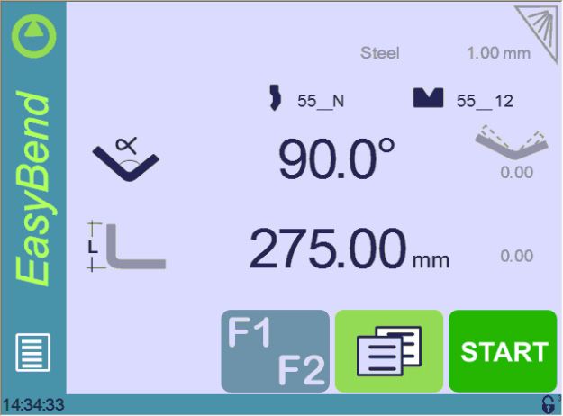
EasyBend Page
(Menu Button) → EasyBend
The EasyBend page is used for individual bends, for example when an external worker
needs to interrupt production just to make a single bend (usually with the same tools).
The program currently being used for production is only temporarily interrupted
(no need to save it) when switching to the EasyBend page, and then resumed
again when returning to the program page (Menu Button → Current program).
M aking a bend on the EasyBend Page
See Basic Page Description, page 14 for more information on the different
controls on the EasyBend page.
Setting Instructions:
1. Touch the material’s thickness (here 1.00). The More Page is displayed. Enter the
Material thickness and the Force.
2. If necessary, touch one of the tool’s icon ( or ) to select a punch or die. (To
learn how to configure tools, please refer to section Tools Management, page 19).
3. Enter the angle for the bend you wish to create (here 90°).
4. Enter the flange’s length (here 275.00 mm).
5. Press this button to go to the More Page (see page 15) and enter the
eventually required extra data for the bend.
6. Start the hydraulic pump motor (by pressing this button if available. It turns red
when the motor is running).
7. Press the button to position the machine according to the data that were just
entered.
8. When the machine is ready to bend, a button is displayed.
9. Press the foot switch to execute the bend.
Sep.
30/38 2019
V2.1CybTouch 8 P User Manual
Error and Warning Messages
Following is a list of warning and error
messages which may be displayed on the
interactive message line of the CybTouch.
There are two types of messages:
• Warning Messages, which are displayed
on a green background. They are
information or instructions that will
disappear automatically.
• Error Messages (machine or NC
errors), which are displayed on a red
background. They inform the user of an
error occurring on the machine or NC,
and sometimes require intervention by Interactive Message number
the end user or a technician. message line
When reporting error messages, please ALWAYS indicate the error number at
the end of the line. This number also refers to the first column in the section
below.
Warning Messages
Msg Nr. Message Description
W02 Ignore This message appears when the desired action makes no sense,
like for example clearing the indexation when the indexation was
not made.
W03 Code accepted This message is displayed when the correct password has been
entered.
W04 Please press 3 seconds This message reminds the operator to keep the start pump
button pressed for 3 seconds.
W05 The pump is on This message appears after the pump starting cycle has been
correctly executed.
W06 The pump is off This message indicates that the pump has been stopped.
W07 Machine not indexed Before the machine is indexed, the NC doesn’t know where the
axes are. In manual page, movements are authorized but the
electronic stroke limits are not activated. Operator is responsible
for stopping axis movement before mechanical limit is reached.
W08 Touch OK to continue Indicates that a validation is required to continue.
W10 Cycle in progress While this message is displayed, the machine cycle is in progress
and the screen is locked, except for the Stop button.
W11 Machine is indexed Indicates the indexation cycle was successful.
W12 Identification OK In the Axis Wizard, indicates the identification cycle was
successful.
W15 Input in programming mode ! The “Next Seq+Start” or the “Pressure reached” input is
activated while NC is in programming mode. If the message
persists, check the machine status.
W16 Eco mode This message appears when the Eco mode starts, after the timer
defined in the machine parameters is over.
Sep.
2019 31/38
V2.1® CybTouch 8 P User Manual
Msg Nr. Message Description
W17 Enter the measured angle This message is displayed when the operator must enter the
physically measured angle value in the Bending and Corrections
page.
W18 Empty field Operator did not enter a value.
W19 24V I/O power on 24V to the inputs/outputs is now available.
W20 Please select a field This message is displayed when trying to set the time (see Set
Clock, page 7) and no field (minute, seconds, etc.) has been
selected.
W21 Set seconds
W22 Set minutes
W23 Set hour In the Set Clock (see page 7) page, when the corresponding
field is selected, indicates that it can be set using the up and
W24 Set day down arrows.
W25 Set month
W26 Set year
W29 End of list This message is displayed when reaching the end of the list in
one of the different menus .
W30 Serial number from 100’000 This message appears only when entering the serial number. It
thru 231’071 indicates the range of the number to be entered. Attention, this
operation is normally done at the factory, with a serial number is
related to the options installed on the machine. Do not change it!
W31 New option code When installing a new option in the Service Page (see
page 11).
W32 Data entry in progress Operation impossible: data entry in progress. Wait until the data
is entered to try again.
W33 Indexation in progress Operation impossible: indexation in progress. Wait until the
indexation is finished to try again.
W34 RFlink disconnected When the RFLink connection to a laptop has been shut down
from the latter.
W35 Access not allowed Operator needs another level password.
W37 Moving direction has been Wizard message: Rotary direction of the motor has been
inverted changed.
W38 Counting direction has been Wizard message: Counting direction of the axis has been
inverted changed.
W39 Moving and counting Wizard message: Both the rotary direction of the motor and the
directions have inverted counting have been changed.
W40 OK Indicates a cycle or operation has properly ended.
W41 No movement executed Axis Wizard message: Operator pressed but no movement
was made.
W45 Enter unlock interface This message is displayed when parameter P02.04 Level 0 Lock
password HMI is set to yes and the screen is touched.
W46 Enter password level 1 or This message is displayed when a password of level 1 or higher
greater is needed to execute a specific operation.
W47 Enter password level 3 This message is displayed when a password of level 3 or higher
is needed to execute a specific operation.
W48 Enter new password
These messages are displayed when changing passwords.
W49 Confirm new password
W50 Enter password for backup This message is displayed when trying to create a backup.
W51 Enter password for restore This message is displayed when trying to restore a backup.
Sep.
32/38 2019
V2.1CybTouch 8 P User Manual
Msg Nr. Message Description
W52 Enter password for init This message appears on the page displayed after the system
crashed (soft or hardware problem), when the operator tries to
format the machine.
W53 Enter password for delete all This message is displayed when trying to delete all backups.
backups
Sep.
2019 33/38
V2.1® CybTouch 8 P User Manual
Error Messages
Msg Nr. Message Description
E01 Y - beam collision. Move the Bending depth mechanical stop axis Y cannot move. The beam
beam up is too close to it. Move the beam upward before being able to
modify the position of axis Y (depth stop).
E02 Pump motor off The pump motor needs to be on for the sequence to start.
E03 Buffer Full The part-program memory is full, you cannot add another
sequence.
E04 Code refused The level code to access the selected page is not correct. Try
again or ask for it if you do not have it.
E05 File not compatible The loaded part-program is incompatible with the NC. This part
should be deleted.
E06 Machine parameter file This file is corrupt and cannot be saved. Try to restart the NC. If
problem the problem persists, format the memory.
E07 Machine parameters not This message appears when a software update has been made
compatible, please format data over a much older version and the parameters are no longer
compatible. It can also appear if the uploaded parameters (with
RFlink) are much older or newer than the current software
version and they are not be compatible. A new start up of the
machine must be made. Contact your dealer.
E08 Lismisc File not compatible Information message, which will disappear when restarting the
NC.
E09 Save program problem This file is corrupt and cannot be saved. Try to restart the NC. If
the problem persists, format the memory.
E10 File not found [ ] A file is missing and the code indicates which one. Call Cybelec
with this code to know which file is missing.
E11 Write to file problem This file is corrupt and cannot be saved. Try to restart the NC. If
the problem persists, format the memory.
E12 X smaller than minimum limit Operator entered a value under the limit, or a memorized value in
the program is under the limit. The wrong value flashes and must
be corrected.
E13 X over maximum limit Operator entered a value over the limit, or a memorized value in
the program is over the limit. The wrong value flashes and must
be corrected.
E14 Fw SetVar Error [ ] May occur when a feature is configured, but the dedicated input/
output is not configured. Usually this is solved by loading the
default input/output configuration (see the machine parameters).
E15 Table locked In the machine parameters (pages “Options” and “Control
valves”), there is a small padlock preventing unwanted changes.
This message is displayed when trying to modify the table with a
closed padlock.
E16 Fw Axes Error [ ] ... Axis manager error. The number gives more information. Most
common errors are described in messages E55 to E68.
If other error numbers are listed, please send conditions of
problem, traces and parameters to the Cybelec Technical support
for assistance.
E17 Programming error Machine parameters incorrectly configured, the error page is
displayed.
E18 X under die limit This message appears when the operator programs a value
for the back gauge position (X axis) inferior to the Safety XS
parameter of the die (see How to create or modify a die?, page
21).
Sep.
34/38 2019
V2.1You can also read