Assessment of the venous system by ultrasound - the European ...
←
→
Page content transcription
If your browser does not render page correctly, please read the page content below

4rd Congress of the European Academy of Neurology

                    Lisbon, Portugal, June 16 - 19, 2018

                               Hands-on Course 5

             Ultrasound in vascular diagnosis - Level 1

Assessment of the venous system by ultrasound
                                José Valdueza
                              Bad Segeberg, Germany

Email: jose.valdueza@segebergerkliniken.de
Conflict of interest:
The author has no conflict of interest in relation to this manuscript

GENERAL VENOUS ANATOMY

Vascular ultrasound studies in neurology have almost been focuses on the

cerebral arteries. Reasons for the relative lack of understanding of the

venous part of cerebral circulation have been the lower absolute numbers

of solely venous diseases, the assumed greater anatomic variability of

veins and sinuses, and technical limitations of analysis of “low-flow”

vessels. However, the intracranial venous circulation, assumed to be 60–70

% of the global cerebral blood volume, does have an important role in the

equilibrium of cerebral perfusion and also is involved in a variety of

vascular pathologies, e.g., AVMs and dural fistulas and cerebral sinus and

venous thrombosis (Stolz 1999).

The potential pathophysiological role of the cervical and cerebral venous

system is actually discussed in several other diseases, especially in

transient global amnesia (Schreiber et al. 2005), idiopathic intracranial

hypertension (Nedelmann et al. 2009), and even in acute arterial stroke

(Pranevicius et al. 2011). One of the most controversial theory in

neurology during the last years, however, the so called “chronic

cerebrospinal venous insufficiency” and its pathophysiological role in

multiple sclerosis (Zamboni 2009) however was recently refuted (Valdueza

et al. 2013).

                                     1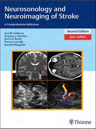
Two peculiarities have to be mentioned comparing intracranial venous

vessels with the general venous system: They do not collapse, even if the

transmural pressure is zero (e.g. in an upright body position). Secondly,

there is complete absence of any venous valves up to the level of the

internal jugular veins, permitting free blood flow in any direction

depending on need.

Intracranial Venous Anatomy

The intracranial veins can be divided into a larger superficial venous

system draining the blood from the hemispheres and a smaller deep

venous system collecting blood from the thalamus, white matter, and

basal ganglia. The superficial veins over both hemispheres connect to a

vascular network which can be classified, according to the common flow

direction, into ascending and descending veins. The ascending veins take

the blood via 10–12 bridging veins into the superior sagittal sinus (SSS).

The most prominent of these veins is the vein of Trolard, located in the

post-central region. The most prominent descending superficial veins are

the vein of Labbé, draining into the transverse sinus (TS), and the sylvian

vein, also called superficial middle cerebral vein, predominantly draining

into the sphenoparietal sinus (SpPS). The main deep cerebral veins are the

paired basal veins of Rosenthal (BVR) collecting blood from both anterior

cerebral veins (ACVs) and both deep middle cerebral veins (DMCVs), the

internal cerebral veins (ICVs) with their tributaries, the thalamostriatal

veins and septal veins of the cavum septum pellucidi. The BVR and ICV

flows into the unpaired vein of Galen (VG) which along with the inferior

sagittal sinus (ISS) merge to form the straight sinus (StS) The venous

sinuses are the final recipients of the blood. In contrast with the other

intracranial veins they have an almost fixed diameter as they are

                                    2
surrounded by an inflexible dural sheath. The StS and SSS merge

occipitally at the confluence of sinuses (CoS) and split into the paired (but

usually asymmetric) transverse sinuses which then take the blood via the

sigmoid sinus (SiS) into the internal jugular veins (IJV). Besides the CoS

the paired cavernous sinus (CS) is another major blood collecting and

distributing venous segment, especially in younger subjects. It collects

blood from the orbit and from the sylvian veins mainly via the SpPS. From

there the blood can be distributed via the inferior petrosal sinus (IPS) or

superior petrosal sinus (SPS) into the IJVs or alternatively via the

emissaries of the skull base into the pterygoid plexus (Figs. 1 and 2).

                                             Fig.   1:   Schematic   drawing    of   the
                                             cerebral venous system. 1 = sylvian vein
                                             (superficial middle cerebral vein); 2 =
                                             vein of Trolard (postcentral vein); 3 =
                                             vein of Labbé; 4 = Rolandic vein (central
                                             vein) 5: anterior cerebral vein; 6 = deep
                                             middle cerebral vein; 7 = basal vein of
                                             Rosenthal; 8 = internal cerebral vein; 9 =
                                             vein of Galen. Venous vessel segments
                                             accessible with duplex sonography are
                                             shown in blue.

                                             Fig.   2:   Schematic   drawing    of   the
                                             cerebral venous system. 1 = superior
                                             sagittal sinus; 2 = inferior sagittal sinus;
                                             3 = internal cerebral vein; 4 = vein of
                                             Galen; 5 = straight sinus; 6 = confluence
                                             of sinuses; 7 = transverse sinus; 8 =
                                             basal vein of Rosenthal; 9 = sigmoid
                                             sinus; 10 = internal jugular vein, 11 =
                                             basilar plexus; 12 = inferior petrosal
                                             sinus; 13 = cavernous sinus; 14 =
                                             pterygoid plexus; 15 = sphenoparietal
sinus; 16 = superior petrosal sinus. Venous vessel segments accessible with duplex
sonography are shown in blue.

                                        3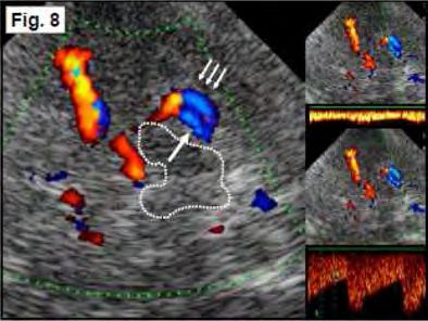
Extracranial Venous Anatomy

The paired IJVs are the main cerebral drainage pathways, collecting the

blood via the superior jugular bulb from the SiS and the IPS (Fig. 3).

However, this dominance is usually restricted to the supine position.

Changing to an upright position a dramatic reduction and even complete

cessation of jugular blood flow can be observed (Valdueza et al. 2000). At

the same time an increase in blood flow can be detected in the vertebral

venous system (VVS) (Fig. 4). The VVS consists of a complex vessel

configuration with several longitudinal valveless channels, connected via

multiple segmental anastomoses. The total cross-sectional area of the VVS

surpasses that of the IJVs. The vertebral veins (VVs) are an important part

of the VVS. They run parallel as single or doubled vessels to the vertebral

arteries (VAs) through the first to sixth transverse processes of the

cervical vertebra. Like a rope-ladder, there are multiple radicular veins,

connecting with the intraspinal part of the VVS via the neural foramina.

The VVs frequently drain into the brachiocephalic or subclavian vein.

However, they may also merge into the IJV before draining into the

brachiocephalic and superior vena cava (Fig. 5).

                                                    Fig. 3: Schematic drawing of the jugular
                                                    drainage system. 1 = superior sagittal
                                                    sinus; 2 = confluence of sinuses; 3 =
                                                    sigmoid sinus; 4 = superior bulb of the
                                                    internal jugular vein; 5 = pterygoid
                                                    plexus; 6 = sub-occipital plexus; 7 (1-3)
                                                    = internal jugular vein (IJV), 7-1 = IJV
                                                    segment 1; 7-2= IJV segment 2; 7-3= IJV
                                                    segment 3 with valves; 8 (1-3) vertebral
                                                    vein (VV), 8-1= VV segment 1 with
                                                    valves; 8-2 = VV segment 2; 8-3 = VV
segment 3; 9 = deep cervical vein; 10 = anterior intraspinal segment of the vertebral venous
system; 11 = subclavian vein. Black-dotted lines indicate the clavicle.

                                              4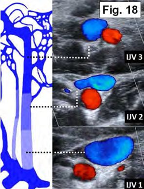
Fig.   4:   Schematic     drawing      of   the
                                                    vertebral venous system. Left: The
                                                    ramified intraspinal segment of the
                                                    vertebral    venous     system    is    nicely
                                                    demonstrated in this historical picture
                                                    (adapted    from    Bock     1823).     Right:
                                                    Schematic drawing of the cervical spine
                                                    (brown), cervical spinal cord and roots
                                                    (yellow), transverse plane: Vertebral
                                                    venous system. 1 = anterior intraspinal
                                                    segment;    2   =     posterior   intraspinal
segment; 3 = vertebral vein as part of the posterior extra-spinal segment; 4 = anterior
extraspinal segment; 5 = transverse radicular veins vein communicating between the
extraspinal and intraspinal venous vessels. Note also the small segmental communicating
veins between the anterior and posterior intraspinal longitudinal orientated veins.

                                                    Fig. 5: Anatomy of the extracranial
                                                    venous drainage pathways Left: DSA,
                                                    right IJV injection. Right: 3D time-
                                                    resolved MRA. 1 = internal jugular vein;
                                                    2 = vertebral vein; 3 = intraspinal
                                                    segment of the vertebral venous system.
                                                    Note the highly complex craniocervical
                                                    junction (arrowheads).

GENERAL STRUCTURE OF VENOUS ULTRASOUND EXAMINATION

For insonation of the cerebral veins, like for the insonation of the arteries

supplying the brain, the patient should lie in a comfortable supine

position. In general, the access paths and transducers used are also

identical. However, the system settings including filters and the PRF have

to be adjusted for the analysis of low-velocity signals, i.e., filters have to

be switched off and the PRF must be reduced. Extracranially, the

patient’s head needs to be in a straight position to avoid flow alterations

caused by unilateral or bilateral venous outflow obstruction. Also, care

must be taken to not compress, e.g., the IJV when the transducer is

applied to the skin of the neck if reliable velocity measurements are to be

                                             5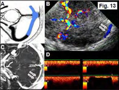
taken. Because of the strong dependency of venous outflow on body

position, the patient should preferably be studied in a completely supine

position and if possible without elevating the head. Similar to arterial

insonation, we recommend usually using angle-corrected measurements

for extracranial and non-angle corrected measurements for intracranial

measurements.

The following section is ordered according to the flow of blood from the

brain toward the heart, i.e., from the distal intracranial to the proximal

cervical vessels. Instructions for insonation focus on duplex ultrasound

only. TCD also allows analysis of the intracranial venous vessels but even

more that in the arterial system has clear limitations because of the lack

of spatial orientation

INTRACRANIAL VEINS AND SINUSES

Similar to the examination of intracranial arteries a sector transducer with

transmission frequencies of between 1 MHz and 3 MHz is required for

vessel analysis. A low PRF facilitates venous vessels detection. The

intraobserver and interobserver variability is low if non-angle corrected

velocities are used (Stolz et al. 2001). Venous flow velocities can vary

greatly in the vessels’ inflow and outflow regions. Flow velocity analysis

should only be performed if the vessel is clearly visible. Measurements at

junctions with other vessels should be avoided.

                                     6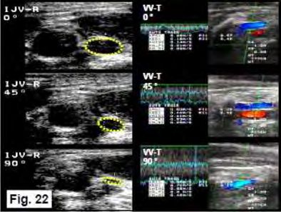
Deep Middle Cerebral Vein (DMCV)

Anatomic details: The DMCV is found in up to 80 % of cases and receives

blood from the insular region and the caudal parts of the striatum. It runs

directly adjacent to the MCA. At the level of the optic chiasm it unites

with the ACV to form the BVR. Sometimes it may directly drain via a

sylvian vein into the CS. Position and vessel identification: The vessel is

visualized via the transtemporal bone window using the axial mid-brain

plane (Fig. 6). The DMCV is best identified at the transition of the distal

M1-MCA segment to the M2 segment. In most cases a visual differentiation

between the opposite colors signals of the MCA and DMCV will not be

possible because the aliasing phenomenon using a low PRF will cover the

weak venous signal. In M1-MCA occlusion the DMCV becomes clearly

visible. If the distance between the artery and vein is large enough the

DMCV may be detected over a short distance posterior to the MCA.

Doppler analysis reveals a venous spectrum in up to 90 % of cases if the

Doppler sample volume is positioned within the posterior border of the

MCA color signal. The flow direction is away from the probe.

                                                  Fig. 6: A Schematic drawing, axial
                                                  plane. Note the blue DMCV (arrows). B
                                                  TCCS,       trans-       temporal     approach,
                                                  midbrain      axial       plane.    Color-mode
                                                  imaging of the DMCV visible as a small
                                                  blue-coded segment (arrows). Note the
                                                  presence      of     a   blue-coded     M2-MCA
                                                  branch with a flow direction away from
                                                  the probe (arrowhead). C CTA, axial
                                                  MIP. DMCV in close spatial relation,
                                                  posterior of the MCA (arrows). Note
again the prominent M2 MCA branch (arrowhead), D Doppler spectrum analysis of the DMCV
(flow velocity: 12/9 cm/s) with a flow away from the probe.

                                            7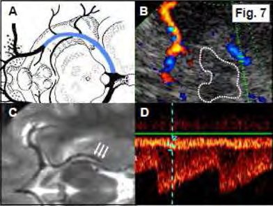
Basal Vein of Rosenthal (BVR)

Anatomic details: The BVR is a very constant vein draining parts of the

frontobasal brain, the hippocampal and parahippocampal region, the

uncus, the limbic system, the hypothalamus, the mesencephalon, the

basal ganglia, the internal capsule, and the insular region. The vessel can

be divided into three segments. In its classic variant, the anterior seg-

ment evolves from the confluence of the DMCV, inferior thalamostriatal

vein and ACV. In its middle segment it runs parallel and superior to the

P2-PCA    and      proximal   P3-PCA   segments   in   the   ambient   cistern

circumscribing the midbrain. The third, posterior segment starts at the

back end of the mesencephalon where it either merges into the ICV or the

VG and in only 8 % of cases directly into the StS. However, in its middle

segment it may also turn caudally to merge via the petrosal vein and into

the SPS. Position and vessel identification: The BVR is best insonated in

its distal segment via the transtemporal bone window using the axial

thalamic plane. More proximal parts can be visualized in the midbrain

plane (Fig. 7). Start insonation by identifying the color signal of the distal

P2-PCA segment. In a number of cases the suspected PCA turns out to be

the BVR as both vessels have identical flow directions. The BVR may have

a larger diameter than the PCA, which may then lead to a stronger color

signal. The proximal BVR is found lateral of the proximal P2-PCA segment,

and similar to the PCA with a flow toward the transducer. The distal BVR,

which is easier to detect, runs medial and superior to the P2-PCA and P3-

PCA segments with a flow direction away from the transducer. Sometimes,

the BVR and the distal P2 and P3-PCA segment can be identified as two

parallel running blue-coded vessel segments, medial the vein, lateral the

artery (Fig. 8).

                                       8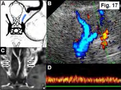
Fig. 7: A Schematic drawing, axial
                                                   plane: Note the blue-colored BVR. B
                                                   TCCS, transtemporal approach, midbrain
                                                   to thalamic axial plane: Color-mode
                                                   imaging of the BVR as a blue-coded
                                                   segment. C MRI T2-weighted image,
                                                   axial plane: Note the DMCV merging into
                                                   the BVR which encircles the midbrain
                                                   (arrows). Note the PCA medial to the
                                                   BVR. D Doppler spectrum analysis of the
                                                   BVR (flow velocity: 15/12 cm/s) with a
flow away from the probe. Note the simultaneous imaging of the PCA and BVR spectrum
despite the color image demonstrating only one vessel signal.

                                                   Fig. 8: Left: Color mode imaging of
                                                   vessels in the ambient cistern, midbrain
                                                   encircled in white- dotted lines. Note
                                                   that in this case two vessels can be
                                                   distinguished in color-mode with the
                                                   BVR located more medially (arrow) and
                                                   the distal P2-PCA located more laterally
                                                   (arrows). Right: Color mode image and
                                                   Doppler spectrum analysis of the BVR
                                                   (top) and the distal P2- PCA (bottom).

Great cerebral vein or vein of Galen (VG)

Anatomic details: The VG is located in the quadrigeminal cistern. It is a

short unpaired vessel draining into the StS. Position and vessel

identification: The VG can be easily insonated through the transtemporal

bone window using an axial thalamic insonation plane in the midline

posterior to the hyperechogenic pineal gland. It can also be found by

following the signal of the BVR until its junction with the VG (Fig. 9). The

point, where the VG turns into the StS can usually not be visualized.

Reported success rates for VG insonation vary from 30 % to 90 %.

                                             9
Fig. 9: A Schematic drawing, sagittal
plane. Note the blue-colored VG. B
TCCS, transtemporal approach, thalamic
to cella media axial plane. Color-mode
imaging of the VG as a small blue- coded
segment posterior to the hyperechogenic
pineal gland (arrow). C CTA, axial MIP.
Note both ICV and BVR merging into the
VG (arrows). D Doppler spectrum
analysis of the VG (flow velocity: 11/8
cm/s) with a flow away from the probe.
Straight Sinus (StS)
Anatomic details: The StS is a mainly unpaired, triangular vessel with a
median length of 50 mm. It arises from the merging VGs and the inferior
sagittal sinus and descends toward the confluence of sinuses where it
frequently drains into the confluence sinuum at the internal occipital
protuberance or into preferably the left TS. A double lumen is found in
approximately 15 % of cases. Position and vessel identification: The
proximal StS, like the VG, is insonated through the transtemporal bone
window in an axial thalamic plane. The transition between the VG and
proximal StS is often not clearly defined. To visualize a long longitudinal
segment the transducer position has to be adapted by turning it in a line
between the pineal gland and the internal occipital protuberance to
achieve an oblique axial insonation plane. Therefore, the dorsal part of
the transducer has to be tilted downward. Flow velocities should be
recorded from the middle segment of the vessel to avoid confusion with
the VG or the confluence of sinuses (Fig. 10). Flow turbulences and raised
velocities may be seen in its proximal part presumably caused by a lumen
narrowing within the StS inflow region or because of large Pacchionian
granulations (Fig. 11). Variations of blood flow velocities may also be seen
because of its triangular shape and varying lumen diameters. Reported
rates of detection vary between 50 % and 80 %. Because of the straight
10vessel course blood flow velocities may be measured using angle
correction.
Fig. 10: A Schematic drawing, sagittal
plane. Note the blue-colored StS. B
TCCS, trans- temporal approach,
thalamic to lower pontine oblique axial
plane. Color-mode imaging of the distal
StS visible as a blue-coded segment
pointing toward the hyperechogenic
internal occipital protuberance (arrow-
head). C CTA, lateral midsagittal MIP.
Note the StS (arrows). D Doppler
spectrum analysis of the StS (flow
velocity without angle correction: 18/14 cm/s; with angle correction: 42/34 cm/s) with a
flow away from the probe.
Fig. 11: A CTA, lateral midsagittal MIP.
Note the lack of contrast in the
transitional region between VG and StS
which indicates a large Pacchionian
granulation (arrow). B Color mode
imaging of the transition between the
BVR, VG, and the StS. Note the aliasing
phenomenon in the proximal StS
(arrow). C,D TCCS, transtemporal
approach, thalamic plane. Color-mode
imaging Doppler spectrum analysis of
the StS revealing a non-pathologic elevated venous flow velocity (flow velocity: 71/42
cm/s) which is probably caused by a large Pacchionian granulation.
Confluence Sinuum (CoS), Transverse Sinus (TS), and Superior Sagittal
Sinus (SSS)
Anatomic details: The CoS is one of the main venous blood distributors
located directly in front of internal occipital protuberance. It collects
blood from the super-ficial venous system via the SSS as well as from the
deep venous drainage system via the StS and connects both with each
other. From there it transfers the blood via the paired TS and SiS into both
IJVs. However a “perfect” CoS only exists in about 20 % of cases (Fig. 12).
11Fig. 12: Schematic drawing of the main
drainage patterns of the SSS and StS and
anatomical variants of the CoS.
Mostly, the drainage is asymmetric with the SSS more frequently passing
the blood into the right TS and the StS draining into the left TS. A
complete separation of superficial and deep venous drainage which means
that no CoS is present can be assumed in about 10 % of cases. The
adjacent TS runs horizontally from the internal occipital protuberance to
the edge of the petrous bone pyramid where it turns downward to become
the SiS. Differences between the right and left sides are frequent. Aplasia
of the TS has been reported in conventional angiography in up to 3% on
the right and up to 14 % on the left. With regard to the diameter, a right-
sided dominance is found in about 50 % of cases and a left-sided
dominance in 25 % of cases. Bilaterally symmetric transverse sinuses are
observed in the remaining 25 % of cases. Position and vessel
identification: The TS, CoS, and distal part of the SSS can be visualized
through the transtemporal bone window in a modified thalamic, midbrain
or upper pontine axial plane. Best results are achieved for the TS if the
contralateral side is insonated. At first, the insonation depth has to be
increased up to 14 cm to visualize the contralateral skull and the
hyperechogenic internal occipital protuberance. Then, a small color
window with low or maximal reduced PRF is placed above the presumed
CoS. Standard TCCS examination of the TS refers to the contralateral side
which is identified with a signal away from the probe close to the skull. In
general its most proximal part is detected but the TS may be followed
12over a distance of about 2 cm including the middle and distal segments.
The ipsilateral TS with a signal toward the probe is considered to be more
difficult to detect. Extracranial compression of the IJV leads to an
immediate reduction or even cessation of flow in the ipsilateral TS and a
flow increase in the contralateral TS if a patent CoS is present (Fig. 13).
Reported detection rates vary between 30 % and 60%. To avoid direct
insonation of the CoS inflow region we recommend placing the Doppler
sample outside the midline. To identify the SSS, the transducer direction
is, starting from the CoS or TS, slightly tilted superior. A signal adjacent
to the calvarium, with flow direction toward the probe is considered to be
the distal SSS (Fig. 14). Reported insonation rates are about 50 %. A
missing TS flow signal may be caused by inadequate insonation condition
or hypoplasia. The latter one can be considered if a prominent flow is
seen in the contralateral TS, provided that insonation conditions are good.
Transient manual occlusion of the dominant IJV may lead to a visible flow
in the hypoplastic TS, therefore excluding TS occlusion.
Fig. 13: A Schematic drawing, axial
plane. Note the blue-colored contra-
lateral and ipsilateral TS as well as the
CoS. B TCCS, transtemporal approach,
midbrain to upper pontine and mild
oblique axial plane. Color-mode imaging
of the blue-coded contralateral TS over
a length of several centimeters (arrows).
Note that also the ipsilateral and
contralateral M1-MCA, A1-ACA, P1-PCA
and P2-PCA as well as the A2-ACA are
visible C MR contrast-enhanced T1-weighted image, axial MIP. Note one hypoplastic TS
(arrows). D Top: Doppler spectrum analysis of the left TS at rest (flow velocity: 17/12 cm/s)
with a flow away from the probe. Bottom left: Increase of flow during right-sided IJV
compression. Bottom right: Interruption of flow during left-sided IJV compression.
13Fig. 14: A Schematic drawing, sagittal
plane. Note the distal part of the SSS
(shown in blue). B TCCS, transtemporal
approach, upper pontine to thalamic
axial plane. Color-mode imaging of the
distal SSS demonstrated as a red-coded
vessel segment. C CTA, midsagittal MIP.
SSS segments accessible to duplex
ultrasound are marked (arrows) D
Doppler spectrum analysis of the SSS
(flow velocity: 11/ 8 cm/s) with a flow
towards the probe.
Sphenoparietal Sinus (SpPS)
Anatomic details: The SpPS can be divided into two parts. In its first part
it runs parallel to the middle meningeal artery along the frontotemporal
surface of the brain. Then it turns and runs without an accompanying
artery along the lesser wing of the sphenoid bone toward the anterior
segment of the CS. In up to 60 % of cases it collects the blood from the
sylvian veins, and therefore from a considerable part of the MCA territory.
Position and vessel identification: The SpPS can be insonated through the
transtemporal bone window using the upper pontine axial insonation
plane. Start identifying the hyperechogenic lesser wing of the sphenoid
bone in the conventional B-mode. Then a small color window with a low
PRF setting is placed over this region. The SpPS, or alternatively, a strong
sylvian vein can then be identified as a venous signal along the sphenoid
bone, aiming toward the carotid siphon (Fig. 15). Flow is directed away
from the transducer. Sometimes the distal part of the SpPS is detected in
the midbrain plane. It can then be seen anteriorly of the MCA. The SpPS
should not be confounded with the DMCV as the SpPS runs anteriorly of
the MCA while the DMCV has a course dorsal to the MCA. A frequent
finding is that the flow velocities increases the closer the vessel gets to
the CS. Venous flow velocities may there reach up to 80 cm/s even in
14completely healthy individuals. Underlying reason for this phenomenon
may be a physiological venous narrowing at the entry into the CS
(Valdueza et al. 1998). Detection rates in individuals with a patent
transtemporal bone window reach up to 70 %.
Fig. 15: A Schematic drawing, axial
plane. Note the SphS along the lesser
wing of the sphenoid bone toward the
CS (shown in blue). B TCCS,
transtemporal approach, upper pontine
axial plane: Color-mode imaging of a
blue-coded prominent SphS. Note the
comma- shaped carotid siphon. C CTA,
axial MIP: Note the close spatial
relation of the distal SphS (arrows) and
the carotid siphon (arrow) D Doppler
spectrum analysis of the SphS (flow velocity: 19/16 cm/s) with a flow away from the probe.
Cavernous Sinus (CS)
Anatomic details: The paired CS is a complex venous structure responsible
for collection and distribution of a considerable amount of cerebral blood.
It has a length of approximately 2 cm in the anteroposterior direction,
extending from the superior orbital fossa to the top of the petrosal
pyramid. It receives blood from the orbit via the superior orbital veins,
from the insular and opercular region as well as the temporal lobes via
sylvian veins and SpPS. Its main drainage follows the IPS into the superior
jugular bulb and via the basal emissaries (foramen lacerum, rotundum,
ovale, and spinosum) toward the pterygoid plexus. However, it is also
connected with the proximal SiS via the SPS. Position and vessel
identification: A critical point of analysis is the inflow and outflow region
of the CS due to its complex anatomy. A direct identification of the CS
using transcranial ultrasound is currently not possible. Venous signals that
are depicted within the region of the CS are most probably feeding or
draining vessel segments. Turbulent signals and high-flow velocities can
15frequently be seen and should not be confounded with real stenoses or
increased flow caused by collateral venous function in a presumed
venoocclusive disorder.
Superior Petrosal Sinus (SPS)
Anatomic details: The SPS is in most cases a drainage pathway for the CS
toward the IJV via the SiS, running along the petrous bone from medial
toward a lateral direction. However, depending on need, the flow
direction might also be toward the CS. Position and vessel identification:
The SPS can be visualized through the transtemporal bone window using
the axial upper pontine plane. If detectable, often a prominent vessel in
projection of the C4/C5 segment of the ICA is found (Fig. 16). Flow
direction can be variable—toward or away from the transducer—but is
usually away from the probe. Insonation rates have not been reported.
Fig. 16: A Schematic drawing, axial
plane. Note the blue SPS along its
course at the upper edge of the
petrous bone connecting the CS with
the SiS. B TCCS, transtemporal
approach, upper pontine axial plane.
Color-mode imaging of a blue-coded
SPS indicating flow toward the SiS
(arrows). Note the color signal of the
carotid siphon (arrow). C CTA, axial
MIP. Note the SPS originating from the
CS (arrows). D Doppler spectrum analysis of the SPS: Rare case with prominent flow (flow
velocity: 26/12 cm/s) with a flow away from the probe.
Inferior Petrosal Sinus (IPS)
Anatomic details: The IPS is an important venous vessel receiving blood
from the posterior aspect of the CS. It runs along the petroclival border to
the ipsilateral IJV in most cases or connects to the vertebral venous
system. Its superior part is cone- shaped with a prominent width of 6–16
16mm. Distally, the IPS has a more tubular appearance with a width of 2–7
mm. Right and left asymmetry is frequent with a right-sided dominance in
75 % of cases. Position and vessel identification: Systematic evaluations
have so far only been reported from TCD. Transforaminal insonation yields
a venous signal toward the probe at an insonation depth of approximately
80–90 mm, often simultaneously accompanied by the BA signal. The vessel
can also be visualized with TCCS through the upper and lower
transforaminal insonation plane using the same identification criteria.
Head rotation should be avoided as artificial compression of the IJV
may lead to underestimation or overestimation of velocities (Fig. 17).
Reported TCD detection rates of at least one IPS reach more than 90 %
(Doepp et al. 1999).
Fig. 17: A Schematic drawing adapted to
the ultrasound image, axial plane. Note
the IPS along its course in the petroclival
groove toward the IJV (shown in blue). B
TCCS, upper transforaminal approach.
Color-mode imaging of a prominent long,
red-coded IPS segment lateral of the
ipsilateral VA and BA. C MR contrast-
enhanced T1-weighted sequence,
coronal plane: Image of both IPS
(arrows). Note the wide distance to the
BA in this example. However, in case of a tortuous BA both vessels may be insonated
simultaneously. D Doppler spectrum analysis of the IPS (flow velocity: 24/ 19 cm/s) with a
flow towards the probe.
17EXTRACRANIAL VEINS
Internal Jugular Vein
Anatomic details: The IJV receives its blood from the superior jugular
bulb, which collects blood from the SSS and StS via the TS and SiS and
frequently from the CS via the IPS. A right sided dominance of the IJV
diameter and blood flow in up to 80 % of the population is usually found.
The side of IJV dominance correlates strongly with a preferred drainage of
the SSS into a likewise dominant TS. Below the superior jugular bulb the
IJV runs initially behind and lateral of the ICA but then circumscribes the
ICA from lateral to finally lay ventrolateral of the CCA in most subjects.
However, in a minority of cases, a position ventral, medial or ventro-
medial of the CCA may be observed. During its course the IJV collects
blood from other veins. The main tributaries are the facial vein, the
lingual vein, and the retromandibular vein, draining normally together as
the thyrolinguofacial trunk into the IJV at the level of the carotid
bifurcation. Before merging with the subclavian vein to form the
brachiocephalic vein it dilates to form the inferior jugular bulb where the
commonly paired jugular valves are located. The IJV can be divided into
three segments: a caudal segment containing the inferior jugular bulb
with the bicuspid valves (IJV 1), a middle segment including the
thyrolinguofacial trunk collecting additionally blood from extracranial
head and neck structures (IJV 2), and a cranial segment from the scull
base to the junction with the thyrolinguofacial trunk collecting mainly
intracranial blood (IJV 1) (Fig. 18).
18Fig. 18: Color-coded duplex sonography of the three
internal jugular vein (IJV) segments in cross-
sectional insonation plane: Top: The smaller cranial
(IJV 3) segment, lateral of the internal carotid artery
(ICA), Middle: The middle (IJV 2) segment ventral of
the common carotid artery (CCA) including the
thyrolinguofacial trunk inflow. Bottom: The large
caudal (IJV 1) segment of the jugular bulb at the
level of the venous valve.
Position and vessel identification: The IJV is insonated like the CCA, ICA,
and ECA in cross-sectional and longitudinal insonation planes. Doppler
spectrum should be assessed only in the longitudinal plane using angle
correction. Variations of velocities along the visible vessel course may be
caused by variations of the cross-sectional area. Longitudinal and
transversal B-mode insonation of the caudal segment permits the
visualization of the inferior jugular bulb and the jugular valves. Further
cranial, approximately at the level of the carotid bifurcation, the merging
thyrolinguofacial trunk can be identified (Fig. 19).
Fig. 19: Top: Extracranial duplex,
longitudinal plane: Doppler spectrum
analysis and color- mode image of the
IJV (coded blue). Note the adjacent red-
coded CCA. Bottom: Serial B- mode
image of a jugular valve. A Open valve,
B, C Valve closing.
In contrast to arterial ultrasound, the patient has to be insonated in a
head-straight and strictly supine position to get reliable and reproducible
results. Even a slight turning of the head might lead to one-sided IJV
19compression with subsequent contralateral IJV or ipsilateral VV flow
velocity increases. Elevation of the body leads to a redistribution of
cerebral venous outflow toward the VVS. Head-down tilting leads to an
increased diameter of the IJV which is commonly used to improve
catheterization conditions for central intravenous lines. Finally, insonation
must be done under normal breathing conditions as huge diameter and
flow velocity variations may be induced by forced breathing. However,
sometimes changes can even be seen during normal in- and expiration.
Increase in intrathoracic pressure, e.g., by a Valsalva maneuver, leads to
a raised IJV diameter and cessation of jugular flow which may also be used
in cooperative patients to facilitate central vein catheter placement. In
up to 30 % of the general population a retrograde jugular flow is observed
during a Valsalva maneuver which is caused by an IJV valve incompetence
(Nedelmann et al. 2005) (Fig. 20). Compression of a non-hypoplastic IJV
with normal flow will usually lead to a contralateral IJV increase, provided
that both TS are patent and they are connected via the CoS. Normal
values: Flow profiles can vary considerably. Also, absent flow may be
observed even in a wide-open IJV. Biphasic profiles are more frequent
than monophasic flow patterns. Prominent flow modulations by normal
inspiration and expiration can be observed especially in the elderly.
Fig. 20: Top: Extracranial duplex, cross-
sectional B-mode image of the IJV at
rest (left) and under Valsalva maneuver
(right). Note the distinct enlargement of
IJV lumen during Valsalva. Bottom:
Doppler spectrum with normal jugular
flow (left). Flow reversal during Valsalva
maneuver (start indicated by the arrow)
instead of flow interruption in a patient
with jugular valve incompetence (right).
20Vertebral Vein
Anatomic details: The VVs are one of four longitudinal channel systems of
the vertebral venous systems draining the cerebral blood. Corresponding
to the VA the VVs can be divided into three segments: VV 1 caudal, VV 2 –
transforaminal, and VV 3 – suboccipital (Fig. 3). Similar to the IJV
anatomy, bicuspid valves are present in the caudal VV. In contrast to the
IJVs, the VVs do not collapse on changing from supine into the upright
body position because of their intraforaminal course. Instead, the vessel
diameter slightly increases while flow increases markedly. In parallel,
there is a profound flow reduction in the IJVs (Figs. 21 and 22).
Fig.21: Schematic drawing illustrating
the postural dependency of the cerebral
venous drainage. Top: Venous vessel
CSA and appearance during variations of
volume and transmural pressure. Left:
In the supine position the IJV is wide
and – depending on the volume state
and the central venous pressure – its
shape is oval or round. The blue marked
VV is open but usually shows a low flow.
Note the small diameter. Right: In the
upright position, the IJVs collapse and flow may show complete cessation while VV
simultaneous shows slight compensatory dilation but also increased flow.
Fig. 22: Ultrasound imaging to
document the postural dependency of
the cerebral venous drainage. Left:
Extracranial duplex, B-mode, transversal
planes showing a step-wise collapse of
the right IJV (yellow encircled) from the
lying position (0 °) to the upright
position (90 °). Right: In the same
subject there is a compensatory marked
increase of flow velocity and volume
flow in the standing position.
The VVs however compensate only for about 25 % of the reduction in
jugular drainage (Valdueza et al. 2000). Therefore alternative pathways
like the intraspinal part of the vertebral venous system are assumed to be
activated. Position and vessel identification: For VV insonation we
21recommend first visualizing the V2 segment of the VA. Care must be taken
to adjust the ultrasound system for low flow velocities (low PRF). Also,
concomitant IJV compression has to be avoided. If the artery is identified,
the VV 2 is usually seen in the mid-cervical region mostly as a singular
vessel accompanying the VA ventrally or as two vessels which run parallel
to the VA on either side. The flow direction is inverse to the VA toward
the heart (Fig. 23). Proximal to its intraforaminal course (caudal of the
C6 segment) the VV can be followed further into the VV 1 segment within
the VA vicinity where becomes larger. The blood flow velocity in this
region is often significantly higher compared to the cranial segments,
probably due to the inflow of intersegmental radicular veins of the
intraspinal VVS. The VV normally drains into the brachiocephalic vein but
may also merge into the IJV. Reference data of VV flow is available from
one publication only (Hoffmann et al. 1999). VV 2 detection rates in the
supine body position of a normal population are bilaterally 62 % and
unilaterally 17 %. About 20 % of cases do not show any VV signal.
Detection rates decrease with increasing age and significantly increase in
an upright body position. Bilateral compression of the IJV leads in many
cases to a VV flow increase of more than 100 %, which underlines its
importance as collateral pathway in IJV obstruction (Schreiber et al
2003d).
Fig. 23: Extracranial duplex. Top left:
Longitudinal B-mode VV and VA image.
VA diameter:
3.8 mm. VV diameter: 1.3 mm. Bottom
left: Corresponding color-mode image.
Note the intersegmental radicular veins
connecting the VV with the anterior
intraspinal segment (arrowhead) and a
second VV medially of the VA (arrow).
Top right: VA Doppler spectrum (flow
velocity: 63/25 cm/s). Middle right: VV
Doppler spectrum (flow velocity: 24/21 cm/s). Bottom right: VV flow velocity increase
during ipsilateral IJV compression.
22Literature
• Doepp F, Hoffmann O, Lehmann R, Valdueza JM. Transcranial Doppler
examination of the inferior petrosal sinus using the suboccipital approach. J
Neuroimaging 1999;9:193–197Hoffmann et al. 1999
• Nedelmann M, Eicke BM, Dieterich M. Functional and morphological criteria of
internal jugular valve insufficiency as assessed by ultrasound. J Neuroimaging
2005;15:70-75
• Nedelmann M, Kaps M, Mueller-Forell W. Venous obstruction and jugular
valve insufficiency in idiopathic intracranial hypertension. J Neurol
2009;256:964-969
• Pranevicius O, Pranevicius M, Liebeskind DS. Partial aortic occlusion and
cerebral venous steal: venous effects of arterial manipulation in acute stroke.
Stroke 2011;42:1478-1481
• Schreiber SJ, Doepp F, Klingebiel R, Valdueza JM. Internal jugular vein valve
incompetence and intracranial venous anatomy in transient global amnesia. J
Neurol Neurosurg Psychiatry 2005a;76:509-513
• Stolz E, Kaps M, Kern A, Dorndorf W. Transcranial color-coded duplex
sonography of intracranial veins and sinuses in adults. Reference data from 130
volunteers. Stroke 1999;30: 1070–1075
• Stolz E, Babacan SS, Bodeker RH, Gerriets T, Kaps M. Interobserver and
intraobserver reliability of venous transcranial color-coded flow velocity
measurements. J Neuroimaging 2001;11:385–392
• Valdueza JM, Doepp F, Hoffmann O, Lehmann R, Einhäupl KM. Venous Doppler
ultrasound assessment of the anterior parasellar region. Cerebrovasc Dis
1998;8:113–117
• Valdueza JM, von Münster T, Hoffmann O, Schreiber S, Einhäupl KM. Postural
dependency of the cerebral venous outflow. Lancet 2000;355:200–201
• Valdueza JM, Doepp F, Schreiber SJ, et al. What went wrong? The flawed
concept of cerebrospinal venous insufficiency. J Cerebral Blood Flow Metab
2013;33:657-668
• Zamboni P, Galeotti R, Menegatti E, et al. Chronic cerebrospinal venous
insufficiency in patients with multiple sclerosis. J Neurol Neurosurg Psychiatry
2009;80:392-399
23Published: 2017 Published: 2016
24Further Teaching (next course will be 10./11. May 2019, for
preregistration: jose.valdueza@segebergerkliniken.de)
25You can also read