Learn-/Training Document - Siemens
←
→
Page content transcription
If your browser does not render page correctly, please read the page content below

Learn-/Training Document | PA Module P02-02, Edition 02/2020 | Digital Industries, FA

                                                 Learn-/Training Document
                                                 Siemens Automation Cooperates with Education
                                                 (SCE) | As of Version V9 SP1

                                                 PA Module P02-02
                                                 SIMATIC PCS 7 – Alarm engineering

                                                                                                   siemens.com/sce

For unrestricted use in educational / R&D institutions. © Siemens 2020. All rights reserved.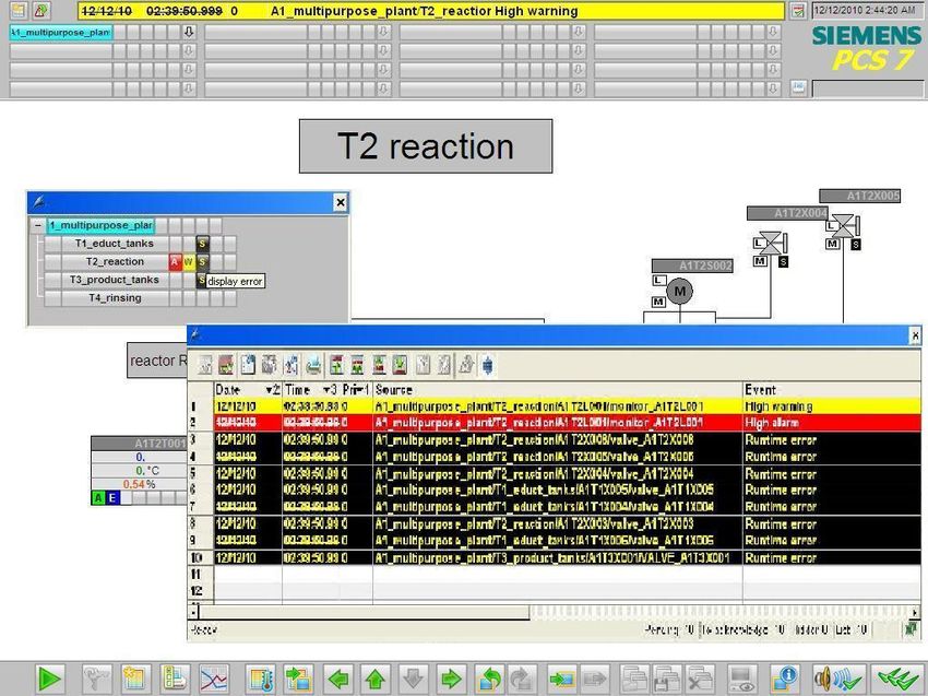
Learn-/Training Document | PA Module P02-02, Edition 02/2020 | Digital Industries, FA Matching SCE Trainer Packages for this Learn-/Training Document • SIMATIC PCS 7 Software Package V9.0 (set of 3) Order No.: 6ES7650-0XX58-0YS5 • SIMATIC PCS 7 Software Package V9.0 (set of 6) Order No.: 6ES7650-0XX58-2YS5 • SIMATIC PCS 7 Software Upgrade Packages (set of 3) Order No.: 6ES7650-0XX58-0YE5 (V8.x V9.0) • SIMIT Simulation Platform with Dongle V10 (contains SIMIT S & CTE, FLOWNET, CONTEC libraries) – 2500 simulation tags Order No.: 6DL8913-0AK00-0AS5 • Upgrade SIMIT Simulation Platform V10 (contains SIMIT S & CTE, FLOWNET, CONTEC libraries) from V8.x/V9.x Order No.: 6DL8913-0AK00-0AS6 • Demo Version SIMIT Simulation Platform V10 Download • SIMATIC PCS 7 AS RTX Box (PROFIBUS) only in combination with ET 200M for RTX – Order No.: 6ES7654-0UE23-0XS1 • ET 200M for RTX Box (PROFIBUS) only in combination with PCS 7 AS RTX Box – Order No.: 6ES7153-2BA10-4AB1 Note that these trainer packages are replaced with successor packages when necessary. An overview of the currently available SCE packages is available at: siemens.com/sce/tp Continued training For regional Siemens SCE continued training, get in touch with your regional SCE contact siemens.com/sce/contact Additional information regarding SCE siemens.com/sce Information regarding use The SCE Learn-/Training Document for the integrated automation solution Totally Integrated Automation (TIA) was prepared for the program "Siemens Automation Cooperates with Education (SCE)" specifically for training purposes for public educational facilities and R&D institutions. Siemens does not guarantee the contents. This document is to be used only for initial training on Siemens products/systems, which means it can be copied in whole or part and given to those being trained for use within the scope of their training. Circulation or copying this Learn-/Training Document and sharing its content is permitted within public training and advanced training facilities for training purposes. Exceptions require written consent from the Siemens. Send all related requests to scesupportfinder.i-ia@siemens.com. Offenders will be held liable. All rights including translation are reserved, particularly if a patent is granted or a utility model or design is registered. Use for industrial customer courses is explicitly not permitted. We do not consent to commercial use of the Learn-/Training Document. For unrestricted use in educational / R&D institutions. © Siemens 2020. All rights reserved. 2 p02-02-alarm-engineering-v9-tud-0719-en.docx
Learn-/Training Document | PA Module P02-02, Edition 02/2020 | Digital Industries, FA

We wish to thank the TU Dresden, particularly Prof. Dr.-Ing. Leon Urbas and the Michael Dziallas
Engineering Corporation and all other involved persons for their support during the preparation of this
Learn-/Training Document.

For unrestricted use in educational / R&D institutions. © Siemens 2020. All rights reserved.                          3
p02-02-alarm-engineering-v9-tud-0719-en.docx
Learn-/Training Document | PA Module P02-02, Edition 02/2020 | Digital Industries, FA

Table of contents
1     Goal ................................................................................................................................................. 5

2     Prerequisite...................................................................................................................................... 5

3     Required hardware and software ...................................................................................................... 6

4     Theory ............................................................................................................................................. 7

    4.1      Theory in brief ..........................................................................................................................7

    4.2      Alarm systems ..........................................................................................................................8

    4.3      Alarms and messages ..............................................................................................................9

    4.4      Alarm processing by the operator ........................................................................................... 11

    4.5      Alarm management in PCS 7.................................................................................................. 14

    4.6      References ............................................................................................................................. 15

5     Task ............................................................................................................................................... 16

6     Planning......................................................................................................................................... 16

7     Learning objective .......................................................................................................................... 16

8     Structured step-by-step instructions................................................................................................ 17

    8.1      Addition of monitoring to the level monitoring .......................................................................... 17

    8.2      Monitoring in faceplate T2_Reaction ....................................................................................... 21

    8.3      Analog level display in faceplate A1_multipurpose_plant ......................................................... 24

    8.4      Binary level display ................................................................................................................. 29

    8.5      Messages in WinCC Runtime ................................................................................................. 34

    8.6      Checklist – step-by-step instruction ......................................................................................... 36

9     Exercises ....................................................................................................................................... 37

    9.1      Tasks ..................................................................................................................................... 37

    9.2      Checklist – exercise ................................................................................................................ 38

10    Additional information ..................................................................................................................... 39

For unrestricted use in educational / R&D institutions. © Siemens 2020. All rights reserved.                                                                     4
p02-02-alarm-engineering-v9-tud-0719-en.docx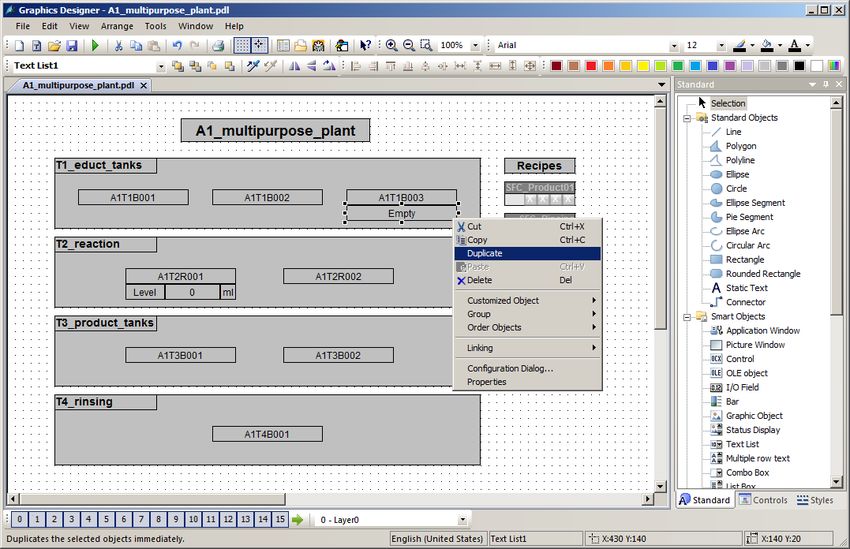
Learn-/Training Document | PA Module P02-02, Edition 02/2020 | Digital Industries, FA

Alarm engineering
1          Goal
           In this module, the students become familiar with the fundamentals of an alarm system. They
           understand the purpose and the areas of application of alarm and signaling systems and they
           know the requirements for such systems resulting from this. They become familiar with the
           possibilities of representation and interactions with messages and alarms. This will enable the
           students to design a suitable and usable alarm management in PCS 7.

2          Prerequisite
           This chapter builds on chapter 'Functional safety'. To implement this chapter, you can use an
           existing project from the previous chapter or the archived project 'p02-01-exercise-r1905-en.zip'
           provided by SCE. The download of the project(s) is stored on the SCE Internet for the respective
           module.

           The (optional) simulation for the SIMIT program can be retrieved from the file 'p01-04-plantsim-
           v10-r1905-en.simarc'. It can be run in demo mode.

For unrestricted use in educational / R&D institutions. © Siemens 2020. All rights reserved.                          5
p02-02-alarm-engineering-v9-tud-0719-en.docx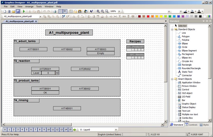
Learn-/Training Document | PA Module P02-02, Edition 02/2020 | Digital Industries, FA
3 Required hardware and software
1 Engineering station: Requirements include hardware and operating system
(for further information, see Readme on the PCS 7 installation DVD)
2 SIMATIC PCS 7 software V9 SP1 or higher
Installed program packages (contained in SIMATIC PCS 7 Software Trainer
Package):
Engineering PCS 7 Engineering
Engineering BATCH Engineering
Runtime Single Station OS Single Station
Runtime Single Station BATCH Single Station
Options SIMATIC Logon
Options S7-PLCSIM V5.4 SP8
3 Demo Version SIMIT Simulation Platform V10
2 SIMATIC PCS 7
V9 SP1 or higher
1 Engineering Station
3 SIMIT V10 or higher
For unrestricted use in educational / R&D institutions. © Siemens 2020. All rights reserved. 6
p02-02-alarm-engineering-v9-tud-0719-en.docx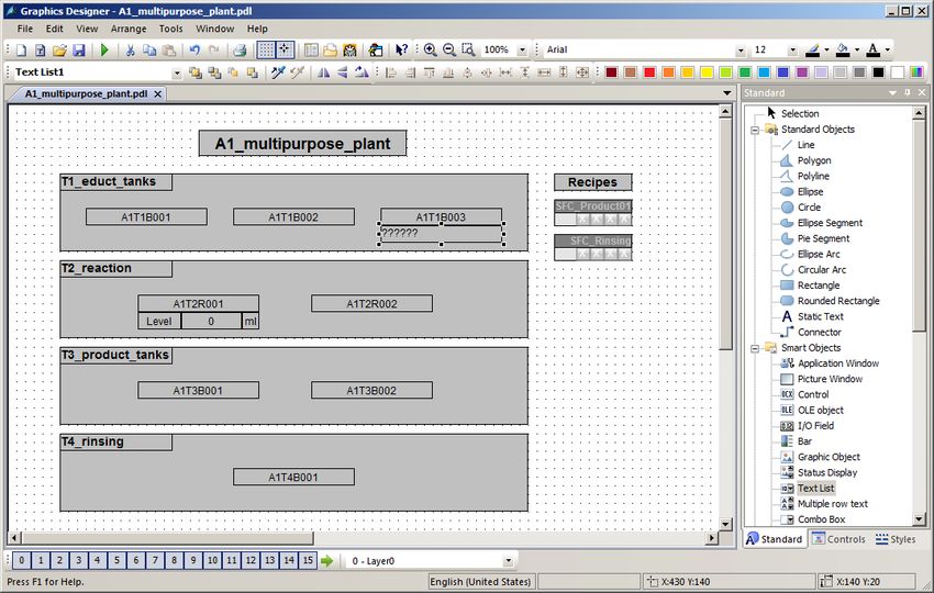
Learn-/Training Document | PA Module P02-02, Edition 02/2020 | Digital Industries, FA

4          Theory
4.1        Theory in brief
           Alarm systems play an extremely important role in modern process control concepts for the
           economic operation of process plants. Designed ergonomically, they inform the operating
           personnel specifically if there are unintended deviations of the process state from a defined
           normal state (refer also to the chapter 'Functional Safety'). They allow the operator to locate the
           cause of the malfunction directly and to adjust the process control strategy through tailored
           interventions As a result, specification-conforming products can continue to be manufactured
           despite the fault, or the process can be stabilized in a way that the fault causes a minimal
           production outage.

           The PCS 7 control system includes a number of technical resources for implementing an alarm
           system. The palette ranges from function blocks for generating alarms, icons for representing
           alarm states and group alarms along the plant hierarchy to components for representing and
           managing alarms in lists (refer to Figure 1).

           By following a set of design rules for specifying alarms texts and assigning priorities, an effective
           alarm system can be implemented very efficiently that meets all the requirements of the
           applicable national and international standards and guidelines.

           Figure 1: From alarm block to display in the faceplate and alarm lists

For unrestricted use in educational / R&D institutions. © Siemens 2020. All rights reserved.                          7
p02-02-alarm-engineering-v9-tud-0719-en.docx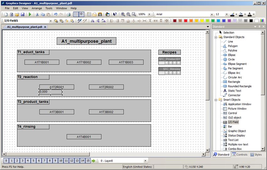
Learn-/Training Document | PA Module P02-02, Edition 02/2020 | Digital Industries, FA

4.2        Alarm systems
           Through the consistent use of modern process control engineering, process plants are highly
           automated and optimized regarding safety. For this reason, the operator of such a plant monitors
           a largely automated process that only requires operator control actions if, because of a fault state
           of the process or the plant, a manual intervention is necessary. The objective of such a manual
           intervention is always to return the process to the OK range (refer also to the chapter ‘Functional
           Safety') before the automatic safety devices are activated.

           Since safety devices generally take the monitored technical facility to a safe state, this results in a
           loss in product quality, production delays or even the standstill of the entire production. This has
           a considerable negative effect on the economics of the plant. For that reason, the risk that an
           impermissible fault state will trigger a safety device must be recognized early so that a suitable
           manual intervention can prevent this. In addition, the operator is to be informed of the activation
           of a safety device so that the consequences can be monitored.

           The alarm system is the central interface between the operator and the monitored process and
           provides everything for managing messages and alarms in the control system [2]. It allows the
           operate to detect deviations from normal conditions within the range of the intended operation
           early and to specifically counteract them. Figure 2 shows the four phases of interaction between
           the operator and the alarm system of the process control system.

                                                                                               Alarm system
                                               Generation                                         of DCS

                     Operator                   Process
                      action                                          Representation
                                                 plant

                                               Assessment
                                                                                                 Operator

           Figure 2: Phases of interaction according to [2]

For unrestricted use in educational / R&D institutions. © Siemens 2020. All rights reserved.                          8
p02-02-alarm-engineering-v9-tud-0719-en.docx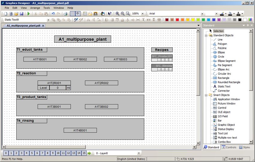
Learn-/Training Document | PA Module P02-02, Edition 02/2020 | Digital Industries, FA

           This means the alarm system has to provide the operator with the capability and the opportunity
           to respond suitably to a signaled event. To attain this, the system has to meet a number of
           requirements. Messages and alarms must be represented clearly, transparently and
           consistently.

           Operators are supported in the situation-oriented evaluation of a message or an alarm as well as
           in the selection of suitable intervention. For this, it is necessary to provide a suitable prompt for
           action, depending on the process state.

           To prevent the operator from becoming overwhelmed, the frequency of appearance of messages
           and alarms must be minimized. The operator can also be supported in his work with suitable
           tools for documenting and evaluating messages and alarms.

           When designing an alarm system, the performance capability limits of the future operators have
           to be taken into account. The total volume of tasks that an alarm system requires an operator to
           perform must not exceed human performance limits either in the short term or long term.

           On the one hand, a short-term sudden rise in the number of alarms or of the alarm rate can
           cause the operator to be briefly overloaded (alarm shower). Note here that on average, an
           operator cannot process more than 7 items of information at the same time (7±2 rule).

           On the other hand, a long-term high workload due to a constantly high number of arriving alarms
           can cause the operator to be permanently overloaded. This leads to an increasing drop of the
           operator's performance and reliability.

           In order to quickly spot important alarms and rare events, they must be highlighted to draw the
           user's attention. Important information should be presented redundantly to make it easier to
           notice. Moreover, if possible, several sensory channels should be addressed for transmitting
           information (for example, through acoustic warning signals).

           Only if an alarm system meets these requirements can it actually support the operator in his job
           of monitoring and controlling the plant.

4.3        Alarms and messages
           Alarm systems are used to manage messages and alarms in control systems. In general, a
           "message" is any report or indication of the occurrence of a specific event. However, in the
           narrower sense the term is used only for such messages that do not require an immediate
           operator response [1].

For unrestricted use in educational / R&D institutions. © Siemens 2020. All rights reserved.                          9
p02-02-alarm-engineering-v9-tud-0719-en.docx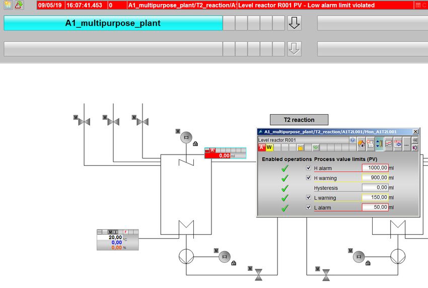
Learn-/Training Document | PA Module P02-02, Edition 02/2020 | Digital Industries, FA

           Otherwise, the term "alarm" is used. The term "message" is thus used as both as a generic term
           and a narrower term. To avoid confusion, the following definitions apply consistently in the
           following:

           –    Alarm: Indication or report of the occurrence of an event that requires an immediate operator
                response. The response may involve an activity; for example, performing an operator control
                action. However, it can also be only a mental response, for example, to increased attention.

           –    Message: Indication or report of the occurrence of an event occurred that requires no
                immediate operator response.

           Alarms signal deviations of the process or of the plant from the normal state and allow the
           operator to avert a dangerous situation or economic damage. To fulfill this task, good alarms
           have to have the following features [3]:

           –    Relevant: The alarm is justified and valuable to the operator.

           –    Clear: The alarm contains information for the operator. It does not repeat another alarm.

           –    Timely: The alarm arrives close to the time when an intervention is necessary. It arrives in
                time for the operator to intervene.

           –    Prioritized: The alarm provides information on how urgent the operator response is.

           –    Can be understood: The alarm contains information that can be understood clearly and
                easily.

           –    Diagnostic: The alarm allows the operator to identify the problem that occurred.

           –    Instructional: The alarm provides suitable action instructions to solve the problem that
                occurred.

           –    Focusing: The alarm guides the attention to the most important problems

               Alarms should always be used purposefully. In so doing, it must be clarified what is being
               monitored, how it is being monitored and when an alarm is triggered. Furthermore, it must be
               defined how the operator can respond to an alarm. Based on these criteria, alarms can be
               subdivided into a variety of alarm types (refer to [3]).

               The most important types are:

               –   Absolute alarm: The alarm is generated when a specified limit is exceeded or dropped
                below.

               –   Time delayed alarm: The alarm is generated when the alarm criterion is met for a
                specified time span.

               –   Process alarm: The control system itself generates an alarm that requires an immediate
                operator response.

For unrestricted use in educational / R&D institutions. © Siemens 2020. All rights reserved.                          10
p02-02-alarm-engineering-v9-tud-0719-en.docx
Learn-/Training Document | PA Module P02-02, Edition 02/2020 | Digital Industries, FA
4.4 Alarm processing by the operator
The operator processes alarms in three phases: First, the operator must recognize that a
problem has occurred (1st phase: Recognition). To this end, the alarm system must draw the
operator's attention to the problem. The operator must then identify the cause of the problem with
the help of the control system (2nd phase: Identification). Once the operator has identified the
cause, he can introduce measures to eliminate the problem and compensate for the
consequences of the problem (3rd phase: Troubleshooting). During each of these phases, the
alarm system must support the operator in a suitable manner. Table 1 lists the most important
support capabilities of the alarm system.
Phase Supporting options of the alarm system
Recognition – Effective guidance of attention
– Suitable presentation of information
– Pre-processing and sampling information
Identification – Significant description of errors
– Tools for investigation of errors
– Jumping to the appropriate operator display of PCS
Troubleshooting – Significant instructions for solving the problem
– Jumping to the appropriate operator display of PCS for operator
intervention
Table 1: Capabilities of the alarm system to support alarm processing
To make appropriate alarm processing possible for the operator of a plant, alarms that occur
have to be suitably managed by the alarm system. Alarm management supports all phases of
interaction between the operator and the alarm system of the process control system.
Generation
Messages and alarms are generated at the process level in the devices of the control equipment
of the plant. Generation may be linked to certain conditions (for example, timing conditions,
hysteresis) and is carried out always with time-synchronous stamping.
When defining messages and alarms, the operator's reaction time has to be taken into account.
After a message or an alarm has occurred, the operator must have sufficient time to eliminate the
reported problem before a subsequent alarm is triggered.
This can be easily illustrated using the overflow protection of a reactor as an example.
Corresponding to the inflow rate of the reactor, a defined time elapses between the overflow
message and the corresponding overflow alarm. If the operator's counter measures cannot take
effect in time, the message is not useful to the operator since the alarm and the automated safety
function are triggered in any case.
For unrestricted use in educational / R&D institutions. © Siemens 2020. All rights reserved. 11
p02-02-alarm-engineering-v9-tud-0719-en.docxLearn-/Training Document | PA Module P02-02, Edition 02/2020 | Digital Industries, FA
Prioritization
Large process plants have a considerable number of alarm sources available that in turn can
trigger different types of alarms. To keep this diversity controllable for the operator, it is advisable
to structure the alarm system. A suitable method for this is alarm prioritization. This refers to the
unambiguous classification of all alarms of an alarm system according to their importance and
urgency [2]. If several alarms are accumulating, a processing sequence can be suggested to the
operator based on alarm priorities.
Priority
Response time Seriousness
Delay in
Shutdown Off spec
production
Priority
< 5 min High Medium Low
5 - 20 min Medium Low Low
> 20 min Low Low Low
Figure 3: Example of a prioritization matrix according to [2]
To this end -as shown in
Response time Seriousness
Delay in
Shutdown Off spec
production
< 5 min High Medium Low
5 - 20 min Medium Low Low
> 20 min Low Low Low
Figure 3- a prioritization matrix can be set up. It depends on the requirements of the
respective process plant and is usually used for the entire plant. Corresponding to this matrix,
each individual alarm is assigned a priority (static prioritization).
Alternatively, alarms can also be prioritized depending on the current plant situation and the
combination of other queued alarms (dynamic prioritization). Usually, alarms are marked in
color according to their priority.
For unrestricted use in educational / R&D institutions. © Siemens 2020. All rights reserved. 12
p02-02-alarm-engineering-v9-tud-0719-en.docxLearn-/Training Document | PA Module P02-02, Edition 02/2020 | Digital Industries, FA
Prioritization is designed in a way that the long-term average alarm rate for each operator station
in normal operation is not more than one alarm every ten minutes [2]. For this reason, an
appropriate priority distribution is the aim. For example:
– 5% Priority High
– 15% Priority Medium
– 80% Priority Low
The reduction of operator load resulting from this avoids overload consequences and ensures
necessary time is left free for operator control and monitoring [2].
For unrestricted use in educational / R&D institutions. © Siemens 2020. All rights reserved. 13
p02-02-alarm-engineering-v9-tud-0719-en.docxLearn-/Training Document | PA Module P02-02, Edition 02/2020 | Digital Industries, FA
Representation
The representation of alarms is of vital importance to the usability of an alarm system. The
representations below have proven themselves in practice and have prevailed [2]:
– Area overview of alarms: Arrangement of the alarms in an overall view that cannot be
covered up (also called common status display). The alarms are arranged in a way that
they can be assigned directly to the corresponding plant sections. Using corresponding jump
functions, the assigned process and plant pictures are directly accessible.
– Representing alarms using an alarm list: Listing of the queued alarms in list form.
Numerous options are available for sorting and filtering the list. Jump functions to the
assigned process and plant pictures are also often offered in this type of representation.
– Alarm representation in a schematic flow diagram: Alarms are signaled through
saturated colors (preferably red or yellow) of the corresponding symbols in the process or
plant picture.
– First value alarm system: If alarms accumulate, the system determines the primary alarm
and filters out the subsequent alarms resulting from it. For the operator, this decreases the
number of alarms he has to process.
Often, the graphic representations are supplemented by visual or acoustic signal transmitters.
They additionally inform operators that an alarm has occurred.
Operators must acknowledge alarms and messages that occurred. With that action, operators
document that they have taken notice of the state change.
Evaluation
In order to evaluate an alarm or a message, the operator must be able to interpret the current
process and plant state correctly. He is assisted in doing this by the types of representation just
discussed, by suitable alarm texts and alarm descriptions as well as suitable tools for pre-
processing larger alarm volumes.
Operator intervention
After the operator has evaluated the state of the plant and the consequences of the alarm, he
must decide on an appropriate action and implement it. This takes place within the control system
but outside the alarm system. It is therefore extremely helpful to the operator if he can jump from
the alarm system directly to the corresponding faceplate where the necessary operator control
intervention can be taken. Often, alarm systems provide corresponding jump functions. In
addition, decisions regarding operator action are supported with help texts that are assigned to
the different alarms.
For unrestricted use in educational / R&D institutions. © Siemens 2020. All rights reserved. 14
p02-02-alarm-engineering-v9-tud-0719-en.docxLearn-/Training Document | PA Module P02-02, Edition 02/2020 | Digital Industries, FA
4.5 Alarm management in PCS 7
PCS 7 has an efficient alarm system. It informs the plant operator about occurring events and
indicates them in the form of message lists and a group display during process operation. An
additional list shows the operator control interventions of the plant operator. The message display
is configured in WinCC.
PCS 7 differentiates three message classes [4]:
– Process control messages are generated in PCS 7 by driver blocks if they detect faults
in their own components (AS, OS etc.) These messages do not have to be configured.
– Process messages signal events of the automated process such as limit violations and
operational messages. These messages do not have to be configured. However, alarm texts
and priority can be changed if needed.
– Operator input messages are generated when process tags are controlled, for example,
on a changeover of the operating mode. Operator input messages are generated
automatically if the faceplates of the PCS 7 Advanced Process Library or user-
configured, PCS 7-compliant blocks are used.
Messages for the AS and distributed I/O are configured when the CFCs are created or in the
process object view. Messages of block types or individual block instances can be changed, and
a user's own alarm texts can be configured. SFCs, types and instances can also generate
messages.
Messages for the OS are configured using the Alarm Logging application in WinCC
Explorer. There, the triggering event is specified for a message.
When configuring messages, different aspects have to be taken into account: The most important
aspects are explained briefly below:
– Alarm text Blocks with signaling behavior have preset alarm texts with the corresponding
alarm class and alarm type. These texts and attributes can be adapted depending on
requirements. In addition, information from the process or the block comment can be inserted
in the message text as associated values.
– Alarm number: During compilation, each message configured in the engineering station is
automatically assigned a unique message number in alarm logging. The alarm number range
is specified when the project is set up. Alarm numbers are assigned either project-wide or
CPU-wide and are unique. The latter is a precondition for assigning message priorities.
– Alarm priority: A message can be assigned a priority between 0 (the lowest) and 16 (the
highest). Alarm lists can be sorted and filtered by priority. The message line in the overview
area always displays the message that has the highest priority and has not yet been
acknowledged.
For unrestricted use in educational / R&D institutions. © Siemens 2020. All rights reserved. 15
p02-02-alarm-engineering-v9-tud-0719-en.docxLearn-/Training Document | PA Module P02-02, Edition 02/2020 | Digital Industries, FA
Technological blocks that are visualized on the OS have the Loop-In-Alarm function. This
makes it possible to change directly from the alarm list to the corresponding faceplate in the case
of process messages and process control messages.
PCS 7 uses a central acknowledgment concept. If a message is acknowledged on an OS, the
acknowledgment is sent first to the triggering block and is forwarded from there to all other
relevant operator stations.
4.6 References
[1] VDI 3699 (Edition 2014-01): Process control using display screens.
[2] NAMUR NA 102 (Edition 2008-10): Alarm Management.
[3] EEMUA 191 (Edition 2013, Edition 3): Alarm Systems.
[4] SIEMENS (2017-10): Process Control System PCS 7: OS Process Control (V9.0 SP1).
A5E39221482-AB. (support.industry.siemens.com/cs/ww/en/view/109754981)
For unrestricted use in educational / R&D institutions. © Siemens 2020. All rights reserved. 16
p02-02-alarm-engineering-v9-tud-0719-en.docxLearn-/Training Document | PA Module P02-02, Edition 02/2020 | Digital Industries, FA
5 Task
In this task, alarms and warnings will be created for the operator system (OS). As an example,
you will program a level monitoring for Reactor A1T2R001 and see the created alarms and
warnings in WinCC.
6 Planning
The CFC blocks created in the preceding projects already bring their own interface for messages.
These can now be accessed.
Using the monitor block for the A1T2L001 level, it will be shown which messages are available
and how they can be configured and integrated in WinCC. The following limits must be
considered:
– PV_AH_Lim – Alarm High
– PV_WH_Lim – Warning High
– PV_WL_Lim – Warning Low
– PV_AL_Lim – Alarm Low
For a better overview, besides the elements generated by PCS 7, you will create displays for the
levels on the overview picture A1_multipurpose_plant. This will be performed by way of example
for the following elements:
– A1T2L001
– A1T1L003
A subsequent test will ensure that everything is functioning as desired.
7 Learning objective
In this chapter, students learn the following:
– Integration of monitoring and alarm blocks in the CFC
– The alarm system of WinCC
– Representation of alarms and warnings in the operator system (OS)
– Further functions in the WinCC Graphics Designer
For unrestricted use in educational / R&D institutions. © Siemens 2020. All rights reserved. 17
p02-02-alarm-engineering-v9-tud-0719-en.docxLearn-/Training Document | PA Module P02-02, Edition 02/2020 | Digital Industries, FA
8 Structured step-by-step instructions
8.1 Addition of monitoring to the level monitoring
1. To program the level monitoring, first open the existing CFC A1T2L001 for the level of
reactor A1T2R001. ( A1_multipurpose_plant T2_reaction reactor R001 A1T2L001)
2. From the 'Monitor' folder of the PCS 7 Advanced Process Library V9.0, insert the
'MonAnS' block and interconnect it as shown. ( Libraries PCS 7 AP Library V90
Blocks+Templates/Blocks Monitor MonAnS)
For unrestricted use in educational / R&D institutions. © Siemens 2020. All rights reserved. 18
p02-02-alarm-engineering-v9-tud-0719-en.docxLearn-/Training Document | PA Module P02-02, Edition 02/2020 | Digital Industries, FA
Notes:
– The MonAnS block is used to monitor a measured value (analog signal) for the limit pairs:
– Warning limit (high/low)
– Alarm limit (high/low)
3. In the block properties, the I/Os shown below are made visible for setting the high and low
alarm/warning limits. ( PV_AH_Lim PV_WH_Lim PV_WL_Lim PV_AL_Lim
Visible (Invisible))
For unrestricted use in educational / R&D institutions. © Siemens 2020. All rights reserved. 19
p02-02-alarm-engineering-v9-tud-0719-en.docxLearn-/Training Document | PA Module P02-02, Edition 02/2020 | Digital Industries, FA
4. The warning and alarm limits shown are set for the now visible I/Os and the value of the
PV_Unit input is set to '1040'. It specifies the unit that is displayed on the OS screen or in the
faceplate. An excerpt from the Siemens documentation for possible units is also shown
below.
For unrestricted use in educational / R&D institutions. © Siemens 2020. All rights reserved. 20
p02-02-alarm-engineering-v9-tud-0719-en.docxLearn-/Training Document | PA Module P02-02, Edition 02/2020 | Digital Industries, FA
5. Here, all changes in chart 'A1T2L001Sheet1' are listed once more:
Block Catalog/Folder Number of connectors
Libraries/PCS 7 AP Library V9.0/
MonAnS
Blocks+Templates\Blocks/Monitor
Table 2: New blocks in chart 'A1T2L001Sheet1'
Input Wiring to Inverted
MonAnS.PV Pcs7AnIn.PV_Out
MonAnS.PV_AH_Lim 1000.0
MonAnS.PV_WH_Lim 900.0
MonAnS.PV_WL_Lim 150.0
MonAnS.PV_AL_Lim 50.0
MonAnS.PV_Unit 1040
Pcs7AnIn.PV_InUnit 1040
Table 3: Input interconnections in chart 'A1T2L001Sheet1'
Output Wiring to Inverted
none none none
Table 4: Output interconnections in chart 'A1T2L001Sheet1'
For unrestricted use in educational / R&D institutions. © Siemens 2020. All rights reserved. 21
p02-02-alarm-engineering-v9-tud-0719-en.docxLearn-/Training Document | PA Module P02-02, Edition 02/2020 | Digital Industries, FA
8.2 Monitoring in faceplate T2_Reaction
1. To compile and download AS and OS at the same time, select the project in the component
view of SIMATIC Manager. Then, select 'Compile and Download' for the PLC. (
SCE_PCS7_Prj PLC Compile and Download Objects)
2. Next, as shown here, select the objects for compiling and start the process as you learned in
the previous chapters. ( Start)
For unrestricted use in educational / R&D institutions. © Siemens 2020. All rights reserved. 22
p02-02-alarm-engineering-v9-tud-0719-en.docxLearn-/Training Document | PA Module P02-02, Edition 02/2020 | Digital Industries, FA
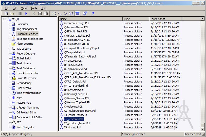
3. After successful compilation, open the OS. ( OS(1) Open Object)
4. Within WinCC, open the picture 'T2_reaction.Pdl' in the Graphics Designer.
( Graphics Designer T2_reaction.Pdl)
For unrestricted use in educational / R&D institutions. © Siemens 2020. All rights reserved. 23
p02-02-alarm-engineering-v9-tud-0719-en.docxLearn-/Training Document | PA Module P02-02, Edition 02/2020 | Digital Industries, FA
5. In this picture, the block icon for the MonAnS block 'A1T2L001' was already created during
the compilation run. Position it to the right of the reactor and save the picture. ( A1T2L001
)
For unrestricted use in educational / R&D institutions. © Siemens 2020. All rights reserved. 24
p02-02-alarm-engineering-v9-tud-0719-en.docxLearn-/Training Document | PA Module P02-02, Edition 02/2020 | Digital Industries, FA
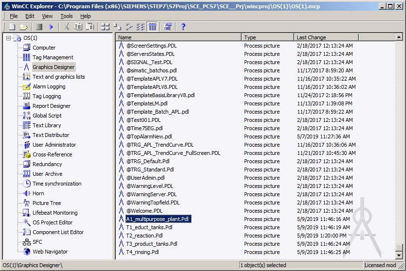
8.3 Analog level display in faceplate A1_multipurpose_plant
1. Open the picture 'A1_multipurpose_plant.Pdl' in the Graphics Designer.
( Graphics Designer A1_multipurpose_plant.Pdl)
For unrestricted use in educational / R&D institutions. © Siemens 2020. All rights reserved. 25
p02-02-alarm-engineering-v9-tud-0719-en.docxLearn-/Training Document | PA Module P02-02, Edition 02/2020 | Digital Industries, FA
2. In this picture, drag an I/O field from the smart objects of the object palette to display the
level of Reactor A1T2R001. Then, open its tag selection. ( Standard palette Smart
Objects I/O Field )
For unrestricted use in educational / R&D institutions. © Siemens 2020. All rights reserved. 26
p02-02-alarm-engineering-v9-tud-0719-en.docxLearn-/Training Document | PA Module P02-02, Edition 02/2020 | Digital Industries, FA
3. Within the tag selection, select the engineering station variables as the data source. In the
left window you will then see the hierarchy of your project. Here you can easily locate your
MonAnS block. For the display in the I/O field, select the 'PV#Value' I/O. ( ES Variables
A1_multipurpose_plant T2_reaction reactor R001 A1T2L001 Mon_A1T2L001
PV#Value OK)
4. This tag is now displayed in the configuration dialog. After the following changes, accept this
configuration. ( Update: Upon change Field type: Output OK)
For unrestricted use in educational / R&D institutions. © Siemens 2020. All rights reserved. 27
p02-02-alarm-engineering-v9-tud-0719-en.docxLearn-/Training Document | PA Module P02-02, Edition 02/2020 | Digital Industries, FA
5. In the properties of the I/O field, the output format is set to 4 places before the decimal and
no places after the decimal. ( Properties Output/Input Output Format 9999 OK)
6. Next, select the following properties of the font. ( Properties Font X Alignment:
Centered Y Alignment: Centered)
For unrestricted use in educational / R&D institutions. © Siemens 2020. All rights reserved. 28
p02-02-alarm-engineering-v9-tud-0719-en.docxLearn-/Training Document | PA Module P02-02, Edition 02/2020 | Digital Industries, FA
7. To better interpret the value in runtime, enter a tooltip text. ( Properties Miscellaneous
Tooltip Text: Level reactor R001 OK)
8. Next, place the I/O field under Reactor A1T2R001 and add two static texts 'Level' and 'ml'. (
Standard palette Static Text)
For unrestricted use in educational / R&D institutions. © Siemens 2020. All rights reserved. 29
p02-02-alarm-engineering-v9-tud-0719-en.docxLearn-/Training Document | PA Module P02-02, Edition 02/2020 | Digital Industries, FA
8.4 Binary level display
1. Below the Educt tank A1T1B003, a display is to be implemented that indicates whether or not
this tank is empty. A text list will be used for this. Drag this text list from the object palette to
the picture and then open its tag selection. ( Standard palette Smart Objects Text List
)
For unrestricted use in educational / R&D institutions. © Siemens 2020. All rights reserved. 30
p02-02-alarm-engineering-v9-tud-0719-en.docxLearn-/Training Document | PA Module P02-02, Edition 02/2020 | Digital Industries, FA
2. Within the tag selection, select 'STEP 7 Symbol Server' as the data source. You will then see
the symbols of the S7 program in the left window. Here, select the input I70.5
'A1.T1.A1T1L003.LSA-.SA-'. ( STEP 7 Symbol Server S7 Program(1) Symbols
I70.5 'A1.T1.A1T1L003.LSA-.SA-' OK)
3. This tag is then displayed in the configuration dialog. After the following changes, accept this
configuration. ( Update: Upon change Field type: Output OK)
For unrestricted use in educational / R&D institutions. © Siemens 2020. All rights reserved. 31
p02-02-alarm-engineering-v9-tud-0719-en.docxLearn-/Training Document | PA Module P02-02, Edition 02/2020 | Digital Industries, FA
4. Next, you set the representation of the font in the properties of the text list.
( Properties Font X Alignment: Centered Y Alignment: Centered)
5. The texts are assigned to the values of the tag in the Properties also.
( Properties Output/Input Assignments)
6. The text 'Empty' is assigned to the value 0 and 'OK' to the value 1.
( Range type: Single Value Value range: 0 Text: Empty Change Range type:
Single Value Value range: 1 Text: OK Append OK)
For unrestricted use in educational / R&D institutions. © Siemens 2020. All rights reserved. 32
p02-02-alarm-engineering-v9-tud-0719-en.docxLearn-/Training Document | PA Module P02-02, Edition 02/2020 | Digital Industries, FA
7. You will need exactly such a text list once more for a textual display below Product tank
A1T3B001. It will indicate whether or not this tank is full. The previously created text list is
selected and duplicated for this. ( Duplicate)
8. For product tank A1T3B001, select input I70.6 'A1.T3.A1T3L001.LSA+.SA+'. ( STEP 7
Symbol Server S7 Program(1) Symbols E70.6 'A1.T3.A1T3L001.LSA+.SA+' OK)
For unrestricted use in educational / R&D institutions. © Siemens 2020. All rights reserved. 33
p02-02-alarm-engineering-v9-tud-0719-en.docxLearn-/Training Document | PA Module P02-02, Edition 02/2020 | Digital Industries, FA
9. The assignment is also changed in the properties: This time, the text 'OK' is assigned to the
value 0 and 'Full' to the value 1. ( Range type: Single Value Value range: 0 Text: OK
Change Range type: Single Value Value range: 1 Text: Full Change OK)
10. Place the second text list below Product tank A1T3B001 and save the picture.
( Save )
For unrestricted use in educational / R&D institutions. © Siemens 2020. All rights reserved. 34
p02-02-alarm-engineering-v9-tud-0719-en.docxLearn-/Training Document | PA Module P02-02, Edition 02/2020 | Digital Industries, FA
8.5 Messages in WinCC Runtime
1. The following will show how a warning is displayed in Runtime. The warning or alarm that
occurred last but has not been acknowledged appears in the alarm line. If the operator wants
to change directly to the picture where the alarm or warning was triggered, he can do this in
two ways:
– With the Loop in Alarm button in the alarm line
– By clicking on the fault display in the picture hierarchy ( )
For unrestricted use in educational / R&D institutions. © Siemens 2020. All rights reserved. 35
p02-02-alarm-engineering-v9-tud-0719-en.docxLearn-/Training Document | PA Module P02-02, Edition 02/2020 | Digital Industries, FA
2. In the picture 'T2_Reaction', a display of the warning is provided in the block icon. By clicking
on the block icon, additional information is displayed in the faceplate for the MonAnS block
regarding the cause of the warning. Here, messages requiring acknowledgment can be
acknowledged or limits can be adapted.
3. By clicking on the Alarm System button in the message line, all queued messages are
displayed. ( )
For unrestricted use in educational / R&D institutions. © Siemens 2020. All rights reserved. 36
p02-02-alarm-engineering-v9-tud-0719-en.docxLearn-/Training Document | PA Module P02-02, Edition 02/2020 | Digital Industries, FA
8.6 Checklist – step-by-step instruction
The following checklist helps students to independently check whether all steps of the step-by-
step instruction have been carefully completed and enables them to successfully complete the
module on their own.
No. Description Checked
1 Monitoring of level A1T2L001 added and configured
2 Faceplate T2_reaction contains level monitoring
3 Faceplate A1_multipurpose_plant contains a display of the analog
level A1T2L001
4 Faceplate A1_multipurpose_plant contains a textual display of the
binary levels A1T1L003 and A1T3L001
5 Textual displays display the correct text
6 Alarms in WinCC successfully tested
7 Project successfully archived
Table 5: Checklist for step-by-step instructions
For unrestricted use in educational / R&D institutions. © Siemens 2020. All rights reserved. 37
p02-02-alarm-engineering-v9-tud-0719-en.docxLearn-/Training Document | PA Module P02-02, Edition 02/2020 | Digital Industries, FA
9 Exercises
In the exercises, you apply what you learned in the theory section and in the step-by-step
instructions. The existing multiproject from the step-by-step instructions (p02-02-project-r1905-
en.zip) is used and expanded for this. The download of the project is stored as zip file "Projects"
on the SCE Internet for the respective module.
In the step-by-step instructions, only the alarm for a level of only one reactor was implemented. In
the exercise, the alarm configuration of the level of reactor R002 is to now be completed and
alarms and warnings of temperature violations of both reactors are to be implemented. The
missing displays will then be added to the overview picture.
9.1 Tasks
The tasks below are based on the step-by-step instructions. The corresponding steps of the
instructions can be used to assist with each task.
1. Implement alarm generation also for the level of the second reactor. For this, insert the
MonAnS block in the CFC A1T2L002 and assign a name and parameters to it. After
compilation, place the block in the faceplate 'T2_reaction.pdl'.
2. Next, in the overview display 'A1_multipurpose_plant.pdl', insert an I/O field for the level of
reactor A1T2R002 and visualize the current reactor level.
3. Design alarms for the temperatures of the two reactors similar to the levels. The temperature
warning is to be triggered at 55 °C and the alarm at 60 °C. No additional monitor blocks are
needed to design the temperature warnings and alarms since the PidConL blocks already
include this functionality. The I/Os for the warning and alarm limits have the same name as
in the MonAnS blocks.
4. Create I/O fields for the temperature below the level in the overflow picture. Represent the
temperature with one place after the decimal.
5. Finally, add the missing text lists for all elements.
For unrestricted use in educational / R&D institutions. © Siemens 2020. All rights reserved. 38
p02-02-alarm-engineering-v9-tud-0719-en.docxLearn-/Training Document | PA Module P02-02, Edition 02/2020 | Digital Industries, FA
9.2 Checklist – exercise
The following checklist helps students to independently check whether all steps of the exercise
have been carefully completed and enables them to successfully complete the module on their
own.
No. Description Checked
1 Monitoring of level A1T2L002 added and configured
2 T2_reaction contains monitoring of level A1T2L002
3 Faceplate A1_multipurpose_plant contains a display of the analog
level A1T2L002
4 Monitoring of temperatures A1T2T001 and A1T2T002 configured in
exiting blocks
5 Faceplate A1_multipurpose_plant contains a display of the
temperatures A1T2T001 and A1T2T002 with one place after the
decimal
6 Faceplate A1_multipurpose_plant contains text lists for all binary level
sensors with correct display
7 (optional) New elements successfully tested
8 Project successfully archived
Table 6: Checklist for exercises
For unrestricted use in educational / R&D institutions. © Siemens 2020. All rights reserved. 39
p02-02-alarm-engineering-v9-tud-0719-en.docxLearn-/Training Document | PA Module P02-02, Edition 02/2020 | Digital Industries, FA
10 Additional information
More information for further practice and consolidation is available as orientation, for example:
Getting Started, videos, tutorials, apps, manuals, programming guidelines and trial software/
firmware, under the following link:
siemens.com/sce/pcs7
Preview "Additional information"
For unrestricted use in educational / R&D institutions. © Siemens 2020. All rights reserved. 40
p02-02-alarm-engineering-v9-tud-0719-en.docxLearn-/Training Document | PA Module P02-02, Edition 02/2020 | Digital Industries, FA Further Information Siemens Automation Cooperates with Education siemens.com/sce Siemens SIMATIC PCS 7 siemens.com/pcs7 SCE Learn-/Training Documents siemens.com/sce/documents SCE Trainer Packages siemens.com/sce/tp SCE Contact Partners siemens.com/sce/contact Digital Enterprise siemens.com/digital-enterprise Industrie 4.0 siemens.com/future-of-manufacturing Totally Integrated Automation (TIA) siemens.com/tia TIA Portal siemens.com/tia-portal SIMATIC Controller siemens.com/controller SIMATIC Technical Documentation siemens.com/simatic-docu Industry Online Support support.industry.siemens.com Product catalogue and online ordering system Industry Mall mall.industry.siemens.com Siemens Digital Industries, FA P.O. Box 4848 90026 Nuremberg Germany Subject to change and errors © Siemens 2020 siemens.com/sce For unrestricted use in educational / R&D institutions. © Siemens 2020. All rights reserved. 41 p02-02-alarm-engineering-v9-tud-0719-en.docx
You can also read