Precision gripper Assembly and operating instructions - Afag
←
→
Page content transcription
If your browser does not render page correctly, please read the page content below
Assembly and operating instructions
Precision gripper
PG 12 I PG 16 I PG 20
Translation of the Original Assembly Instructions EN
PG 12 Order no.: 50332223
PG 16 NN Order no.: 50332224
PG 16 NC Order no.: 50531661
PG 16 NO Order no.: 50531662
PG 20 Order no.: 50332225
Assembly Instructions EN PG 12 I PG 16 I PG 20 Edition 03/2021 Rev. 2.5 1–48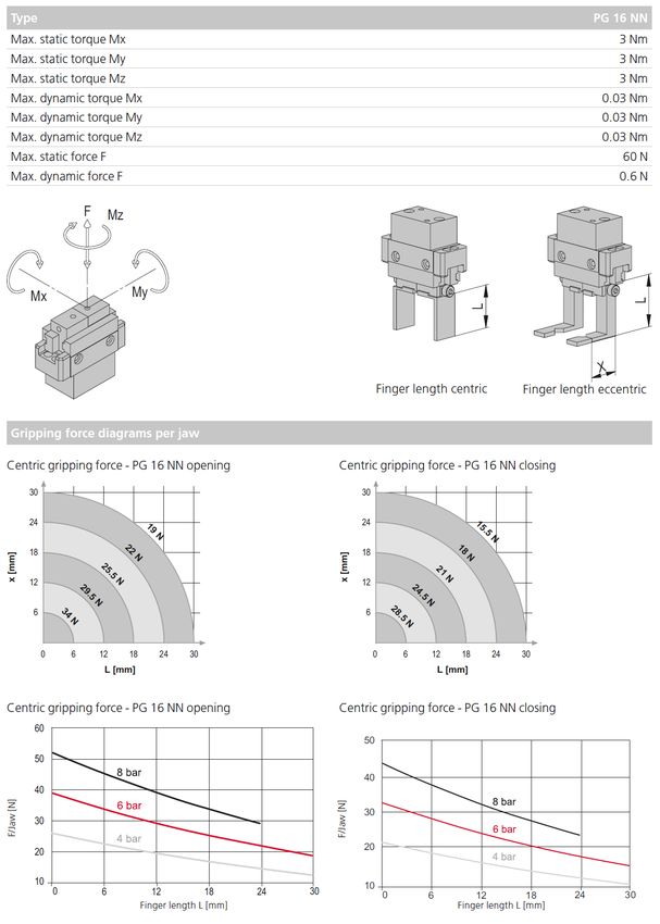
Dear Customer,
Thank you for choosing our products and placing your trust and confidence in
our company!
These assembly and operating instructions contain all essential information you
need about your product. Our aim is to provide the required information as
concisely and clearly as possible. If, however, you still have any questions on
the contents or suggestions, please do not hesitate to contact us. We are always
grateful for any feedback.
Our team will also be glad to answer any further question you may have
regarding the precision gripper or other options.
We wish you every success with our products!
With kind regards
Your Afag team
© Subject to modifications
The precision grippers have been designed by Afag Automation AG according
to the state of the art. Due to the constant technical development and
improvement of our products, we reserve the right to make technical changes
at any time.
© Copyright 2021 Afag Automation AG
All contents of the present assembly and operating instructions, in particular the
texts, photographs and graphics, are protected by copyright. All rights reserved.
No part of these assembly and operating instructions may be reproduced,
distributed (made available to third parties), or transmitted in any form or by any
means, including photocopying, recording, or other electronic or mechanical
methods, without the prior written permission of Afag Automation AG.
Afag Automation AG
Fiechtenstrasse 32
CH - 4950 Huttwil (Switzerland)
Tel.: +41 62 959 86 86
e-mail: sales@afag.com
Internet: www.afag.com
2 – 48 Assembly instructions EN PG 12 I PG 16 I PG 20 Edition 03/2021 Rev. 2.5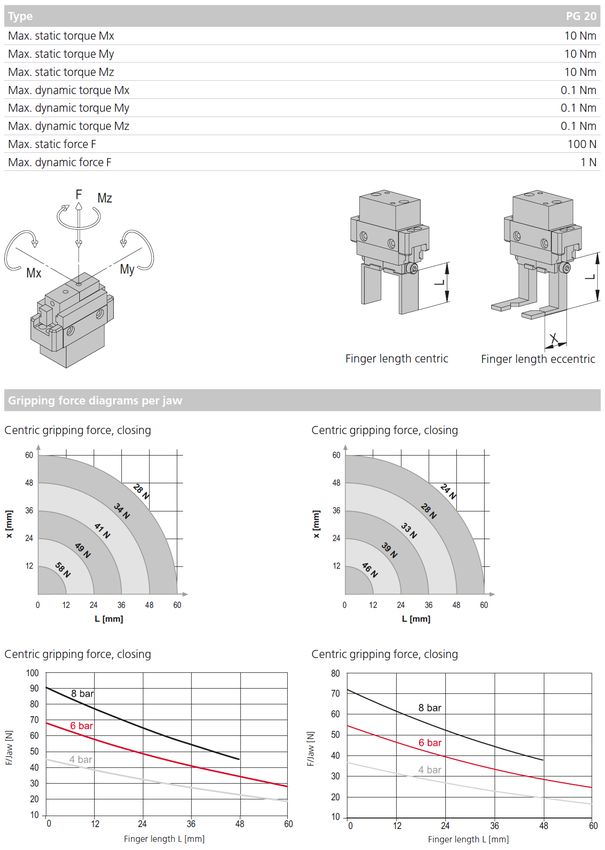
Table of contents
Table of contents
1 General .................................................................................................................... 5
1.1 Contents and purpose of these assembly instructions ................................. 5
1.2 Explanation of symbols................................................................................. 5
1.3 Additional symbols ........................................................................................ 6
1.4 Applicable documents .................................................................................. 7
1.5 Warranty ....................................................................................................... 7
1.6 Liability .......................................................................................................... 7
2 Safety instructions ................................................................................................. 8
2.1 General ......................................................................................................... 8
2.2 Intended use ................................................................................................. 8
2.3 Foreseeable misuse ..................................................................................... 8
2.4 Obligations of the operator and the personnel ............................................. 9
2.4.1 Observe the assembly instructions ........................................................ 9
2.4.2 Obligations of the operating company.................................................... 9
2.4.3 Obligations of the personnel ................................................................ 10
2.5 Personnel requirements ............................................................................. 10
2.5.1 Personnel qualification ......................................................................... 10
2.6 Personal protective equipment (PPE) ........................................................ 11
2.7 Changes & modifications ............................................................................ 11
2.8 General hazards / residual risks ................................................................. 12
2.8.1 General hazards at the workplace ....................................................... 12
2.8.2 Danger due to electricity ...................................................................... 13
2.8.3 Danger due to pneumatics ................................................................... 13
2.8.4 Mechanical hazards ............................................................................. 13
3 Technical data ...................................................................................................... 14
3.1 Precision gripper PG 12 ............................................................................. 14
3.1.1 Dimension drawing PG 12 ................................................................... 14
3.1.2 Technical data PG 12 ........................................................................... 15
3.1.3 Preferred combinations PG 12 ............................................................. 16
3.1.4 Module stresses PG 12 ........................................................................ 17
3.2 Precision gripper PG 16 ............................................................................. 18
3.2.1 Dimensional drawing PG 16 NN .......................................................... 18
3.2.2 Technical data PG 16 NN .................................................................... 19
3.2.3 Dimensional drawing PG 16 NC & PG 16 NO ..................................... 20
3.2.4 Technical data PG 16 NC & PG 16 NO ............................................... 21
3.2.5 Preferred combinations PG 16 ............................................................. 22
3.2.6 Module stresses PG 16 NN .................................................................. 23
3.2.7 Module stresses PG 16 NC & PG 16 NO ............................................ 24
3.3 Precision gripper PG 20 ............................................................................. 25
3.3.1 Dimensional drawing PG 20................................................................. 25
3.3.2 Technical data PG 20 ........................................................................... 26
Assembly Instructions EN PG 12 I PG 16 I PG 20 Edition 03/2021 Rev. 2.5 3–48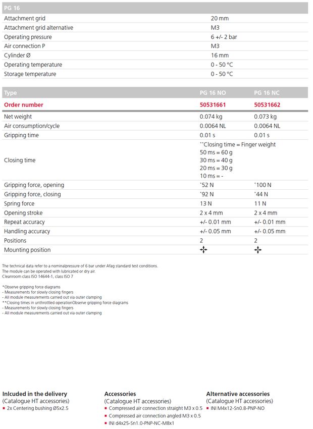
Table of contents
3.3.3 Preferred combinations PG 20 ............................................................. 27
3.3.4 Module stresses PG 20 ........................................................................ 28
4 Transport, packaging and storage ..................................................................... 29
4.1 Safety instructions for transport .................................................................. 29
4.2 Scope of supply .......................................................................................... 29
4.3 Transport .................................................................................................... 30
4.4 Packaging ................................................................................................... 30
4.5 Storage ....................................................................................................... 30
5 Structure and description ................................................................................... 31
5.1 Design precision gripper ............................................................................. 31
5.2 Product description ..................................................................................... 31
5.3 Accessories ................................................................................................ 31
6 Installation, assembly & setting ......................................................................... 32
6.1 Safety Instructions for installation & assembly ........................................... 32
6.2 Assembly & attachment .............................................................................. 33
6.2.1 Attachment ........................................................................................... 33
6.2.2 Tightening torques................................................................................ 33
6.3 Assembly of the gripper fingers .................................................................. 34
6.4 Pneumatic connection ................................................................................ 34
6.5 Installation and adjustment of the inductive sensors .................................. 35
6.5.1 Installation of the inductive sensors ..................................................... 35
6.5.2 Adjustment of the inductive initiators.................................................... 36
7 Commissioning .................................................................................................... 37
7.1 Safety instructions for commissioning ........................................................ 37
7.2 Commissioning of the modules .................................................................. 38
7.3 Setting up & retrofitting ............................................................................... 38
8 Fault elimination................................................................................................... 39
8.1 Safety instructions for troubleshooting ....................................................... 39
8.2 Fault causes and remedy ........................................................................... 39
9 Maintenance and repair ....................................................................................... 40
9.1 General notes ............................................................................................. 40
9.2 Safety instructions for maintenance and repair .......................................... 40
9.3 Maintenance activities and maintenance intervals ..................................... 41
9.3.1 Overview of the maintenance points .................................................... 41
9.3.2 Further maintenance ............................................................................ 41
9.4 Lubrication .................................................................................................. 42
9.5 Spare parts and repair work ....................................................................... 43
10 Decommissioning and disposal ......................................................................... 44
10.1 Safety instructions for decommissioning and disposal ............................... 44
10.2 Decommissioning ....................................................................................... 44
10.3 Disposal ...................................................................................................... 44
11 Declaration of incorporation ............................................................................... 45
4 – 48 Assembly instructions EN PG 12 I PG 16 I PG 20 Edition 03/2021 Rev. 2.5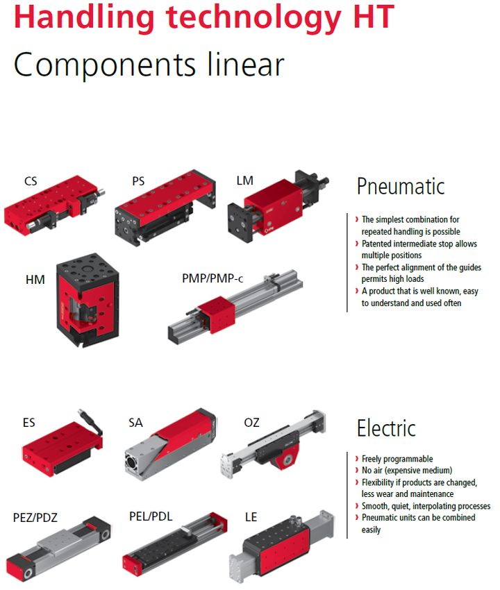
General
1 General
1.1 Contents and purpose of these assembly instructions
These assembly instructions contain important information on assembly,
commissioning, functioning and maintenance of the precision grippers to ensure
safe and efficient handling of the precision grippers PG 12, PG 16 and PG 20.
Consistent compliance with these assembly instructions will ensure:
permanent operational reliability of the precision gripper,
optimal functioning of the precision gripper,
timely detection and elimination of defects (thereby reducing maintenance
and repair costs),
prolongation of the precision gripper’s service life.
The illustrations in this manual shall provide you with a basic understanding of
the module and may vary from the actual design of your module.
1.2 Explanation of symbols
The safety notes are marked by a pictogram and a signal word. The safety notes
describe the extent of the hazard.
DANGER
Danger!
This safety note indicates an imminently hazardous situation which, if not
avoided, will result in death or serious injury.
WARNING
Warning!
This safety note points out a potentially hazardous situation which, if not
avoided, could result in death or serious injury.
CAUTION
Caution!
This safety note points out a potentially dangerous situation which, if not
avoided, can result in minor or slight injuries.
NOTICE
This safety note points out a potentially dangerous situation which, if not
avoided, can cause substantial damage to property and the environment.
Assembly Instructions EN PG 12 I PG 16 I PG 20 Edition 03/2021 Rev. 2.5 5–48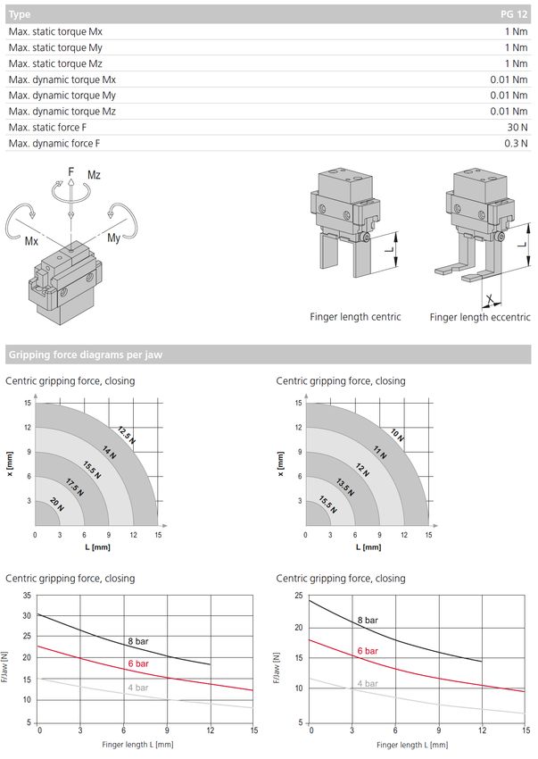
General
This note contains important additional information as well as useful tips for
safe, efficient and trouble-free operation of the precision gripper.
Further warning signs:
Where applicable, the following standardised symbols are used in this manual
to point out the various potential health risks.
Warning - Dangerous electrical voltage.
Warning - Risk of injury from contact with hot surfaces.
Warning - Risk of hand and finger injury due to uncontrolled
movements of components.
Warning - Magnetic field.
Warning - Risk of injury as a result of parts being flung out!
Warning - High noise levels.
1.3 Additional symbols
In these assembly instructions the following symbols are used to highlight
instructions, results, references, etc.
Symbol Description
1. Instructions (steps ...)
Results of actions
References to sections
Enumerations not ordered
6 – 48 Assembly instructions EN PG 12 I PG 16 I PG 20 Edition 03/2021 Rev. 2.5
General
1.4 Applicable documents
Each precision gripper is accompanied by a safety information sheet. This
information sheet must be read carefully by every person who carries out work
on and with the precision gripper.
1.5 Warranty
The warranty terms for Afag handling components and handling systems are
the following:
24 months from initial operation and up to a maximum of 27 months from
delivery.
Wear parts are excluded from the warranty (The customer is entitled to a
product free of defects. This does also apply to defective accessories and
wear parts. Normal wear and tear are excluded from the warranty).
The warranty covers the replacement or repair of defective Afag parts. Further
claims are excluded.
The warranty shall expire in the following cases:
Improper use of the module.
Non-observance of the instructions regarding assembly, commissioning,
operation and maintenance of the module.
Improper assembly, commissioning, operation and maintenance.
Repairs and design changes carried out without prior technical instructions
of Afag Automation AG.
Removing the serial number from the product.
Inadequate checking of wear parts.
Non-observance of the EC Machinery Directive, the Accident Prevention
Regulations, the Standards of the German Electrotechnology Association
(VDE) and these safety and assembly instructions.
1.6 Liability
No changes shall be made to the precision gripper unless described in this
instructions manual or approved in writing by Afag Automation AG.
Afag Automation AG accepts no liability for unauthorized changes or improper
assembly, installation, commissioning, operation, maintenance or repair work.
Assembly Instructions EN PG 12 I PG 16 I PG 20 Edition 03/2021 Rev. 2.5 7–48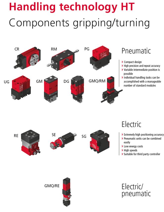
Safety instructions
2 Safety instructions
2.1 General
This chapter provides an overview of all important safety aspects to ensure safe
and proper use of the precision grippers and optimal protection of personnel.
Safe handling and trouble-free operation of the precision grippers requires
knowledge of the basic safety regulations.
Every person carrying out installation, commissioning, maintenance work or
operating the modules must have read and understood the complete user
manual, especially the chapter on safety instructions.
Also observe all rules and regulations regarding accident prevention applicable
to the place of installation of the modules.
Improper use may result in danger to life and limb of the user or third parties or
in damage to the automation system or other material assets.
Failure to follow the directions and safety instructions given in this instructions
manual may result in serious hazards.
2.2 Intended use
The precision grippers series is designed for the shock-free linear movement of
permanently mounted loads in non-explosive environments and in the ambient
and operating specially conditions defined for these modules.
The precision grippers are used in automation systems.
The precision grippers are exclusively intended for operation with original
LinMot components (controller, cables ...).
Any use beyond the described purpose is considered to be not in accordance
with the intended use.
The intended use of the module also includes:
observance of all instructions given in this instructions manual,
compliance with the inspection and maintenance work and the
specifications in the data sheets,
using only original spare parts.
2.3 Foreseeable misuse
Any use other than or beyond the intended use described above is considered
a misuse/improper use of the precision grippers.
Especially the following use is considered a misuse:
Use in potentially explosive atmospheres
8 – 48 Assembly instructions EN PG 12 I PG 16 I PG 20 Edition 03/2021 Rev. 2.5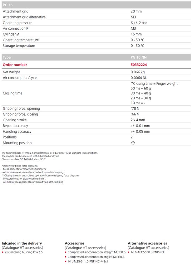
Safety instructions
WARNING
Risk of injury if the module is not used as intended!
The improper use of the precision gripper poses a potential hazard to the
personnel.
The precision gripper may only be used in a technically perfect condition in
accordance with their intended use and instructions in this manual as well
as in compliance with the safety requirements!
Any malfunctions, particularly those that could impair safety, must be
eliminated immediately!
Risks can occur if the module is not used as intended. In the event of
damages caused by improper use the following shall apply:
the operating company shall be solely responsible for such damage, and
AFAG does not accept any liability for damages caused by improper use.
2.4 Obligations of the operator and the personnel
2.4.1 Observe the assembly instructions
A basic prerequisite for safe and proper handling of the parallel gripper is a good
knowledge of the basic safety instructions.
These assembly instructions, in particular the safety instructions contained
therein, must be observed by all persons working with the precision gripper.
2.4.2 Obligations of the operating company
In addition to the safety instructions given in this manual, the operating company
must also comply with the safety, accident prevention and environmental
protection regulations valid for the field of application of the precision gripper.
The operating company is required to use only personnel who:
have the necessary professional qualifications and experience,
are familiar with the basic rules regarding occupational safety and accident
prevention,
have been instructed in the correct handling of the precision gripper,
have read and understood these assembly instructions.
The operating company is also required to:
monitor on an ongoing basis that the personnel work safely considering any
potential hazard involved and the assembly instructions are observed,
ensure that the assembly instructions are always kept at hand at the
automation system in which the precision grippers have been integrated,
observe and communicate universally applicable laws and regulations
regarding accident prevention and environmental protection,
provide the necessary personal protective equipment (e.g. protective
gloves) and instruct the personnel to wear it.
Assembly Instructions EN PG 12 I PG 16 I PG 20 Edition 03/2021 Rev. 2.5 9–48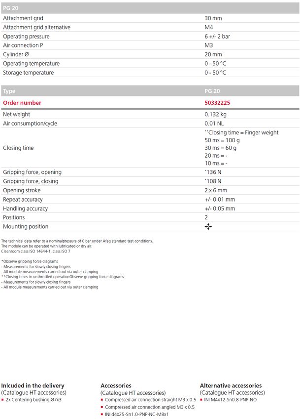
Safety instructions
2.4.3 Obligations of the personnel
All personnel working with the precision gripper are required to:
read and observe these assembly instructions, especially the chapter on
safety,
observe the occupational safety and accident prevention regulations,
observe all safety and warning signs on the precision gripper,
refrain from any activity that might compromise safety and health.
In addition, the personnel must wear the personal protective equipment
required for carrying out their work. (Chapter 2.6).
2.5 Personnel requirements
2.5.1 Personnel qualification
The activities described in the assembly instructions require specific requisites
at the level of professional qualifications of the personnel.
Personnel not having the required qualification will not be able to assess the
risks that may arise from the use of the precision gripper thus exposing himself
and others to the risk of serious injury. Therefore, only qualified personnel may
be permitted to carry out the described activities on the precision gripper.
Persons whose ability to react is restricted due to the intake of medication or the
like must not interact with the precision gripper.
These installation instructions are intended for skilled personnel (installers,
system integrators, maintenance personnel, technicians), electricians and
operating personnel.
The following is a description of the professional skills (qualifications) required
for carrying out the different activities:
Qualified personnel:
Qualified personnel with appropriate training who are qualified due to their
special know-how and fully familiar with the machine and who have been given
instructions on how to carry out the task entrusted to them safely.
Operator (trained personnel):
Authorized persons who due to their specialized professional training,
expertise and experience are capable of identifying risks and preventing
possible hazards arising from the use of the machine.
10 – 48 Assembly instructions EN PG 12 I PG 16 I PG 20 Edition 03/2021 Rev. 2.5Safety instructions
2.6 Personal protective equipment (PPE)
The personal protective equipment serves to protect the personnel from hazards
affecting their safety and health at work.
When working on/with the precision gripper, the personnel must wear the
personal protective equipment assigned by the safety officer of the operating
company or as required by safety regulations. In addition, the personnel are
required to:
wear the personal protective equipment provided by the operating company
(employer),
check the personal protective equipment for proper condition, and
immediately notify the person responsible on site of any defects found on the
personal protective equipment.
Personal protective equipment and the respective mandatory signs:
Protective clothing is a close-fitting clothing specifically
designed to protect personnel from hazards during work.
Protective gloves are specifically designed to protect the
personnel against hand injuries (such as cuts, abrasion,
burns).
Safety shoes are specifically designed to protect the
personnel against foot injuries from crushing, falling objects or
slipping on slippery surfaces.
Hearing protectors are required to protect the personnel
against excessive noise levels to prevent noise-induced
hearing loss.
2.7 Changes & modifications
No changes may be made to the precision grippers which have not been
described in these assembly instructions or approved in writing by Afag
Automation AG.
AFAG Automation AG accepts no liability for unauthorised changes or improper
assembly, installation, commissioning, maintenance or repair work.
The precision grippers may not be changed or modified in any way, except
with the prior written consent of AFAG Automation AG.
Assembly Instructions EN PG 12 I PG 16 I PG 20 Edition 03/2021 Rev. 2.5 11–48Safety instructions
2.8 General hazards / residual risks
Despite the safe design of the precision gripper and the technical protective
measures taken, there still remain residual risks that cannot be avoided and
which present a non-obvious residual risk when operating the precision gripper.
Observe the safety instructions in this chapter and in the other sections of this
manual to avoid damage to property and dangerous situations for the personnel.
2.8.1 General hazards at the workplace
The precision grippers have been built according to the state-of-the-art and the
applicable health and safety requirements. Nevertheless, improper use of the
precision grippers may cause the following hazards to the personnel:
danger to life and limb of the operator or third parties,
on the precision grippers themselves,
property damage.
Always keep the assembly instructions ready at hand at the workplace!
Please, also observe:
the general and local regulations on accident prevention and environmental
protection.
Observe the safety information sheet for the precision grippers.
WARNING
Danger - Do not use in unsuitable environment!
The precision grippers are designed for use in non-explosive atmospheres.
Do not use the precision gripper in potentially explosive atmospheres!
CAUTION
Risk of injuries due to uncontrolled parts movements!
When connecting the precision gripper to the control unit or when operating
the precision gripper sudden, unexpected movements may occur which can
cause personal injury or property damage.
Only qualified personnel may work with or on the precision gripper.
Read the assembly instructions carefully before carrying out any work on
or with the precision gripper.
12 – 48 Assembly instructions EN PG 12 I PG 16 I PG 20 Edition 03/2021 Rev. 2.5Safety instructions
2.8.2 Danger due to electricity
WARNING
Danger! Risk of electric shock!
If work on electrical components is required, ensure that the work is carried
out properly, failure to do so will cause serious or fatal injuries.
Work on the machine's electrical equipment may only be performed by
skilled electrician or trained personnel under the supervision of a skilled
electrician in accordance with all relevant electrical regulations.
2.8.3 Danger due to pneumatics
WARNING
Risks by the pneumatic system!
The pneumatic system can pose various hazards that can cause serious or
fatal injuries if the work is carried out improperly.
Only qualified personnel may work with or on the pneumatic system!
The necessary personal protective equipment must be provided and used.
2.8.4 Mechanical hazards
CAUTION
Danger of injury from moving components!
Limbs can be crushed by moving components!
Work on and with the precision gripper may only be carried out by qualified
personnel.
Never reach into the system during normal operation!
Assembly Instructions EN PG 12 I PG 16 I PG 20 Edition 03/2021 Rev. 2.5 13–48Technical data
3 Technical data
3.1 Precision gripper PG 12
3.1.1 Dimension drawing PG 12
Fig. 1 Dimensional drawing of precision gripper PG 12
14 – 48 Assembly instructions EN PG 12 I PG 16 I PG 20 Edition 03/2021 Rev. 2.5Technical data
3.1.2 Technical data PG 12
Assembly Instructions EN PG 12 I PG 16 I PG 20 Edition 03/2021 Rev. 2.5 15–48Technical data
3.1.3 Preferred combinations PG 12
16 – 48 Assembly instructions EN PG 12 I PG 16 I PG 20 Edition 03/2021 Rev. 2.5Technical data
3.1.4 Module stresses PG 12
Assembly Instructions EN PG 12 I PG 16 I PG 20 Edition 03/2021 Rev. 2.5 17–48Technical data
3.2 Precision gripper PG 16
3.2.1 Dimensional drawing PG 16 NN
Fig. 2 Dimensional drawing of precision gripper PG 16 NN
18 – 48 Assembly instructions EN PG 12 I PG 16 I PG 20 Edition 03/2021 Rev. 2.5Technical data
3.2.2 Technical data PG 16 NN
Assembly Instructions EN PG 12 I PG 16 I PG 20 Edition 03/2021 Rev. 2.5 19–48Technical data
3.2.3 Dimensional drawing PG 16 NC & PG 16 NO
Fig. 3 Dimensional drawing of precision gripper PG 16 NC & PG 16 NO
20 – 48 Assembly instructions EN PG 12 I PG 16 I PG 20 Edition 03/2021 Rev. 2.5Technical data
3.2.4 Technical data PG 16 NC & PG 16 NO
Assembly Instructions EN PG 12 I PG 16 I PG 20 Edition 03/2021 Rev. 2.5 21–48Technical data
3.2.5 Preferred combinations PG 16
22 – 48 Assembly instructions EN PG 12 I PG 16 I PG 20 Edition 03/2021 Rev. 2.5Technical data
3.2.6 Module stresses PG 16 NN
Assembly Instructions EN PG 12 I PG 16 I PG 20 Edition 03/2021 Rev. 2.5 23–48Technical data
3.2.7 Module stresses PG 16 NC & PG 16 NO
24 – 48 Assembly instructions EN PG 12 I PG 16 I PG 20 Edition 03/2021 Rev. 2.5Technical data
3.3 Precision gripper PG 20
3.3.1 Dimensional drawing PG 20
Fig. 4 Dimensional drawing of precision gripper PG 20
Assembly Instructions EN PG 12 I PG 16 I PG 20 Edition 03/2021 Rev. 2.5 25–48Technical data
3.3.2 Technical data PG 20
26 – 48 Assembly instructions EN PG 12 I PG 16 I PG 20 Edition 03/2021 Rev. 2.5Technical data
3.3.3 Preferred combinations PG 20
Assembly Instructions EN PG 12 I PG 16 I PG 20 Edition 03/2021 Rev. 2.5 27–48Technical data
3.3.4 Module stresses PG 20
28 – 48 Assembly instructions EN PG 12 I PG 16 I PG 20 Edition 03/2021 Rev. 2.5Transport, packaging and storage
4 Transport, packaging and storage
4.1 Safety instructions for transport
CAUTION
Risk of injury when packing and unpacking the precision gripper!
The precision gripper can be moved back and forth while they are still loose
and cause crushing injuries.
Pack and unpack the precision gripper carefully.
Also observe the safety instructions in chap. 2 „Safety instructions“ in this
manual.
4.2 Scope of supply
In addition to the assembly and operating instructions, a safety information
sheet is enclosed with each precision gripper.
This information sheet must be read by every person who carries out work
with and on the precision grippers!
Fig. 5 Scope of delivery precision grippers PG 12, PG 16 and PG 20
Unt. PG 12 PG 16 PG 20
1x Module PG 12 Module PG 16 Module PG 16
2x Centering bushing ø4x2 mm Centering bushing ø5x2.5 mm Centering bushing ø7x3
1x Mounting/operating instruct. Mounting/operating instruct. Mounting/operating instruct.
Assembly Instructions EN PG 12 I PG 16 I PG 20 Edition 03/2021 Rev. 2.5 29–48Transport, packaging and storage
4.3 Transport
No liability can be assumed for damages caused by improper installation on
the part of the operating company.
The following conditions must be complied with for transport and storage:
Storage temperature: 0-50 °C
Relative air humidity: < 90%, non condensing
4.4 Packaging
The precision grippers are transported in the transport packaging of AFAG
Automation AG. If no AFAG packaging used, the precision gripper must be
packed so that they are protected against shock and dust.
NOTICE
Risk to the environment due to incorrect disposal of the packaging
material
Environmental damage can be caused by incorrect disposal of the packaging
material.
Dispose of the packaging material in an environmentally sensitive way in
accordance with the local environmental regulations.
4.5 Storage
If the precision grippers are stored for an extended period of time, observe the
following:
Store the precision gripper in the transport packaging
Do not store the precision gripper outdoors or expose them to weather
conditions.
The storage space must be dry and dust free.
Room temperature of the storage space: 0-50 °C.
Relative air humidity: < 90% non condensing.
Clean the precision gripper and protect the blank metal parts against
corrosion using the appropriate means.
Protect the precision gripper from dirt and dust.
30 – 48 Assembly instructions EN PG 12 I PG 16 I PG 20 Edition 03/2021 Rev. 2.5Structure and description
5 Structure and description
5.1 Design precision gripper
3
2
1
4
5 7 6 5
Fig. 6 Design of the precision gripper (example)
1. Gripper housing 5. Air connections at rear/side
2. Gripping head 6. Holders for sensors
3. Gripper jaws 7. Mounting holes (e.g. holding-down unit)
4. Mounting holes for options
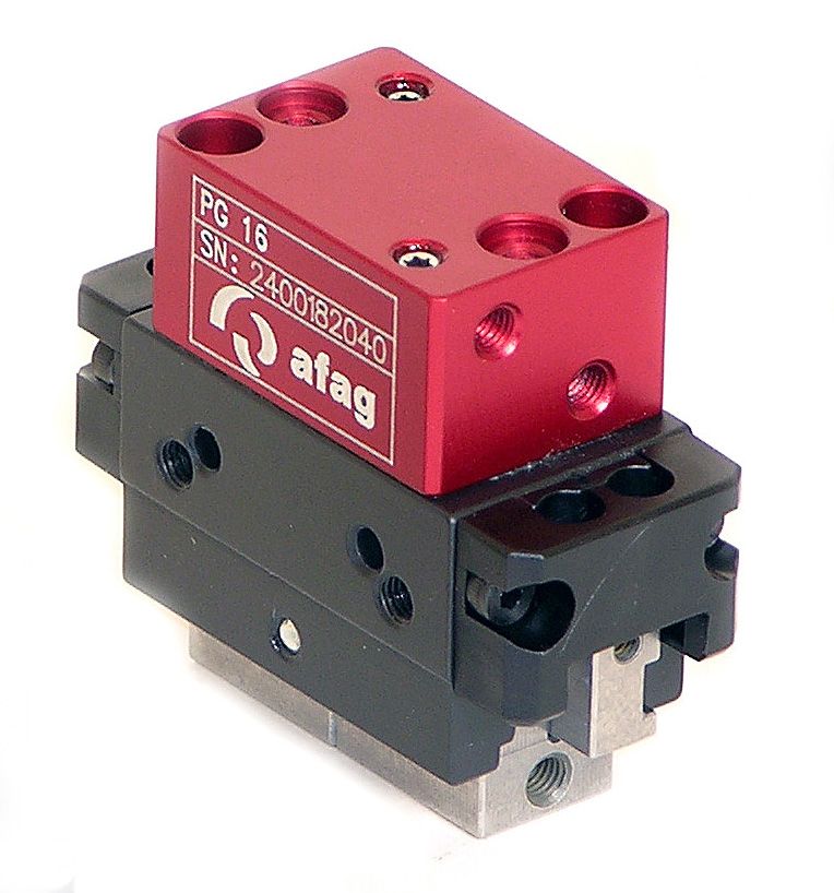
5.2 Product description
AFAG's precision grippers are precise and compact gripping modules designed
for gripping and precise insertion of oriented mass parts. The positions "open"
and "close" can be detected by means of initiators. These initiators are not
included in the standard scope of supply and can be ordered separately.
The precision grippers have a repeatability accuracy of +/- 0.01 mm and a
turning precision of +/- 0.05 mm. The gripping forces are indicated in the
corresponding table of the gripper type in this manual.
Precision grippers can be combined with other modules from the Afag modular
system.
5.3 Accessories
PG 12 PG 16 PG 20
Centring bushing ø 4x2 mm Centring bushing ø 4x2 mm Centring bushing ø 4x2 mm
Order no.: 50332257 Order no.: 50035831 Order no.: 11016850
Initiator INI Ø 3x22-Sn0.8- Initiator INI Ø 4x25-Sn1.0- Initiator INI Ø 4x25-Sn1.0-
PNP-NO-M8x1 PNP-NO-M8x1 PNP-NO-M8x1
Order no.: 50001023 Order no.: 11016714 Order no.: 11016714
Sealing set Sealing set Sealing set
Order no.: 50468493 Order no.: 50468494 Order no.: 50468495
Initiator holder Initiator holder Initiator holder
Order no.: 50466840 Order no.: 50260912 Order no.: 50260914
Assembly Instructions EN PG 12 I PG 16 I PG 20 Edition 03/2021 Rev. 2.5 31–48Installation, assembly & setting
6 Installation, assembly & setting
The customer is responsible for the installation of the precision gripper into
the automation system!
6.1 Safety Instructions for installation & assembly
The precision gripper is an incomplete machine.
For safe operation, the precision grippers must be integrated into the safety
concept of the automation system in which they are installed.
During normal operation it must be ensured that the user cannot interfere with
the working area of the precision gripper.
When installing a precision gripper in an assembly system, the system
operator must provide the system with a protective device with a locked door
safety circuit!
CAUTION
Danger of injury from attachments!
The gripper fingers are pneumatically controlled. Attachments can restrict the
free movement of the gripper fingers and cause injuries such as crushing.
Make sure that the movement of the gripper fingers is not restricted by
mounted attachments.
Take appropriate measures to ensure safe operation!
No liability can be assumed for damages caused by improper
installation/assembling work carried out by the operator.
Also observe the safety instructions in chap. 2 „Safety instructions“ in this
manual.
32 – 48 Assembly instructions EN PG 12 I PG 16 I PG 20 Edition 03/2021 Rev. 2.5Installation, assembly & setting
6.2 Assembly & attachment
The PG precision grippers can be installed in a vertical and horizontal position.
The Afag module components are provided with a precise module centring
which guarantees a high and repetitive accuracy of fit during installation,
operation and exchange of a module.
6.2.1 Attachment
The precision grippers can be mounted at the rear and the side.
Fig. 7 Attachment of the precision gripper (example)
For mounting use the centering sleeves ( chapter 4.2) included in the
scope of delivery.
6.2.2 Tightening torques
For assembling use screws with the following minimum specifications:
Standard VDI 2230
Screw strength Category 8.8
Surface: Galvanized blue, oiled or greased
Thread Tightening torque
M2 0.3 … 0.35 Nm
M2.5 0.5 … 0.73 Nm
M3 1.1 … 1.4 Nm
M4 2.6 … 3.3 Nm
M5 5.2 … 6.5 Nm
M6 9.0 … 11.3 Nm
M8 21.6 … 27.3 Nm
Assembly Instructions EN PG 12 I PG 16 I PG 20 Edition 03/2021 Rev. 2.5 33–48Installation, assembly & setting
6.3 Assembly of the gripper fingers
Example: connection geometry gripper finger
Fig. 8 Connection geometry of gripper finger
6.4 Pneumatic connection
Please see the Technical dimensional drawings in this manual ( Chapter 3)!
Two pneumatic connections each are at the rear and at the sides of the base
body of the pneumatic gripper.
P1
P2
P1= open
P2= close
Fig. 9 Pneumatic connections of the precision gripper
Operating pressure: 6 bar +/- 2
Close air connections which are not used air-tight before installing the module
in a system.
Caution: Carry out a leakage test!
34 – 48 Assembly instructions EN PG 12 I PG 16 I PG 20 Edition 03/2021 Rev. 2.5Installation, assembly & setting
1. Compressed air connection 4. One-way restrictor
2. Maintenance unit 5. Precision gripper
3. 5/2 port directional control valve
Fig. 10 Pneumatic diagram of precision gripper
6.5 Installation and adjustment of the inductive sensors
6.5.1 Installation of the inductive sensors
With the inductive sensors, the opening or closing position of the precision
gripper can be detected. The inductive sensors can be used on both sides of
the black gripper head. This depends on whether the opening or the closing
position is to be detected.
3
2
1
Fig. 11 Installation of inductive sensors
1. Loosen the clamping screws (Fig. 11, 1) on the holder (Fig. 11, 2).
2. Mount the sensors (Fig. 11, 3) to the grippers.
3. Adjust the sensors in unpressurised condition.
4. Tighten clamping screws (Fig. 11, 1) slightly.
5. Check the sensors for proper function.
- Readjust the sensors if necessary ( Chapter 6.5.2).
6. Tighten clamping screws (Fig. 11, 1).
The inductive sensors are mounted.
Assembly Instructions EN PG 12 I PG 16 I PG 20 Edition 03/2021 Rev. 2.5 35–48Installation, assembly & setting
6.5.2 Adjustment of the inductive initiators
The detection position of the gripper jaws is adjusted by turning the screws (Fig.
12, 4) and (Fig. 12, 5). The spacer (Fig. 12, 6) must be shortened according to
the setting. The second spacer (Fig. 12, 7) is mounted when the gripper jaws
grip from the inside to the outside.
1
2
3
4 5 6 7
Fig. 12 Installation of the initiators
1. Proximity switch (see accessories)
2. Clamp holder
3. Allen key
4. Adjustment screw
5. Adjustment screw
6. Spacer (gripper jaws grip from outside to inside)
7. Spacer (gripper jaws grip from inside to outside)
36 – 48 Assembly instructions EN PG 12 I PG 16 I PG 20 Edition 03/2021 Rev. 2.5Commissioning
7 Commissioning
After connection, the precision grippers are put into operation for the first time
via the control.
7.1 Safety instructions for commissioning
CAUTION
Danger of injury in the working area of the precision gripper!
Due to the decentralised control system, the operator of the precision gripper
must not necessarily stand next to the rotary modules during operation so that
he may not have a complete view of the working area. Persons within the
working area may be injured.
When operating the precision gripper, ensure a good overview of the entire
working area.
Unauthorized persons must not stay within the working area during
operation.
CAUTION
Risk of injuries due to uncontrolled parts movements!
When the control unit is switched on, signals from the control unit can lead to
unintentional movements of the precision gripper and cause serious injuries
or material damage.
When working on the precision gripper, make sure that the control unit and
compressed air are switched off and that they cannot be switched on again
unintentionally.
Only connect or disconnect the cables when the control unit is switched off.
Observe the operating instructions of the controller used!
Observe the safety instructions in Chapter 2 "Safety instructions" of these
mounting instructions!
Assembly Instructions EN PG 12 I PG 16 I PG 20 Edition 03/2021 Rev. 2.5 37–48Commissioning
7.2 Commissioning of the modules
NOTICE
Material damage due to improperly carried out work!
The precision grippers are precision mechanical devices and must be
handled with the necessary care and cleanliness during all work.
Commissioning may only be carried out by qualified personnel!
Proceed carefully and follow the instructions step by step when commissioning
the modules for the first time:
1. Slowly pressurize the system.
2. Observe the permissible technical values.
- Payload
- Movement frequency
- Momentary load to the guideways
3. Make sure that there are no persons or tools in the working area.
4. Perform test run:
- Start with slow movements
- Then continue under normal operating conditions
Commissioning is completed.
7.3 Setting up & retrofitting
CAUTION
Risk of injury due to incorrect operation of the system!
Incorrect operation during setup work on the machine can lead to
unintentional starting of the precision gripper and cause injuries.
Setting up and retrofitting work may only be carried out by qualified
personnel.
Observe the operating instructions!
CAUTION
Danger of injury from attachments!
The gripper fingers are electrically controlled. Attachments can restrict the
free movement of the gripper fingers and lead to injuries.
Ensure that the movement of the gripper fingers is not restricted by mounted
attachments.
Take appropriate measures to ensure safe operation!
38 – 48 Assembly instructions EN PG 12 I PG 16 I PG 20 Edition 03/2021 Rev. 2.5Fault elimination
8 Fault elimination
8.1 Safety instructions for troubleshooting
WARNING
Danger of injury due to faulty troubleshooting!
Poorly performed troubleshooting work can lead to serious injuries and
damage to property.
Only use trained specialist personnel for troubleshooting.
All work on the precision gripper must be carried out with the power supply
cut off!
NOTICE
Risk of material damage due to unexpected movements!
There is a risk of material damage if unusual movement of the precision
gripper (e.g. hard shocks) is detected during normal operation.
Stop the system immediately and eliminate the cause!
Also observe the safety instructions in chap. 2 „Safety instructions“ in this
manual.
8.2 Fault causes and remedy
The following table contains an overview of possible fault causes and how to
proceed to eliminate them.
Fault Possible cause Remedy:
Gripper jaws do not return to Payload too high Reduce payload
end position Pressure too low Increase pressure to max. 8 bar
Module defect Send module to Afag for overhaul
Module incorrectly connected Check pneumatic connections and
connect module correctly
Throttle non-return valve Open throttle non-return valve
completely closed
Module audibly loses Leakage from compressed air Check closures on air connections,
compressed air connection retighten if necessary
Leakage from cylinder Send module to AFAG
Assembly Instructions EN PG 12 I PG 16 I PG 20 Edition 03/2021 Rev. 2.5 39–48Maintenance and repair
9 Maintenance and repair
9.1 General notes
The precision grippers are almost maintenance-free. Nevertheless, some
maintenance work must be carried out to ensure an optimum operating
condition of the precision grippers.
9.2 Safety instructions for maintenance and repair
WARNING
Danger of injury due to improper maintenance!
Improperly carried out maintenance activities can cause considerable
damage to property and serious injury.
Only use qualified personnel to carry out the activities.
Always wear personal protective equipment when carrying out maintenance
and repair work!
WARNING
Risk of injuries due to uncontrolled parts movements!
Signals from the control system can trigger unintentional movements of the
precision gripper and cause injury.
Before starting any work on the precision gripper, switch off the control unit
and make sure that it cannot be switched on again unintentionally.
Observe the operating instructions of the controller used!
Before starting any activities, switch off the media supply and make sure it
cannot be switched on again unintentionally!
Also observe the safety instructions in Chapter 2 „Safety instructions“ in
this manual.
40 – 48 Assembly instructions EN PG 12 I PG 16 I PG 20 Edition 03/2021 Rev. 2.5Maintenance and repair
9.3 Maintenance activities and maintenance intervals
Observe the specified maintenance and care intervals. The intervals refer
to normal operating conditions.
9.3.1 Overview of the maintenance points
Fig. 13 Precision gripper
System
No. Maintenance point Maintenance work Interval Remarks
[On/Off]
1 Fasteners Checking After
[Off] -
commissioning
Check fastening elements for tight fit
2 Module Cleaning After
[Off] -
commissioning
- Clean with a dry, lint-free cloth (The precision gripper
must not be sprayed. Do not use aggressive cleaning
agents).
9.3.2 Further maintenance
Further maintenance is not required, if the ambient conditions listed below are
complied with:
Clean working area
No use of splash water
No abrasive or process dust and vapours
Ambient conditions as specified in the technical data
Assembly Instructions EN PG 12 I PG 16 I PG 20 Edition 03/2021 Rev. 2.5 41–48Maintenance and repair
9.4 Lubrication
The precision grippers are lifetime lubricated and can be operated with oil-
lubricated or non oil-lubricated compressed air.
Compressed air specification
Dry (condensation-free)
Filtered (40 μm filter for oil-lubricated air)
Filtered (5 μm filter for oil-lubricated air)
If the precision grippers are operated with lubricated compressed air, we
recommend that you use the following types of oil:
Oil type
Festo Special oil Shell Tellus Oel C 10
Avia Avilub RSL 10 Mobil DTE 21
BP Energol HPL 10 Blaser Blasol 154
Esso Spinesso 10
Oil quantity: 5-10 drops of oil per 1000 ltr. Compressed air
Viscosity range: 9-11 mm2/s (= cST) at 40°C, ISO class VG 10 acc. ISO 3448
NOTICE
Risk of damage to property!
The operation of the gripper modules with oil-lubricated compressed air
causes the factory primary lubrication to be washed out. Therefore, it is
absolutely essential that the gripper modules continue to be operated with oil-
lubricated compressed air in order to avoid damage to the rotary modules.
Once the gripper modules have been operated with oil-lubricated
compressed air, they may never be operated without oil-lubricated
compressed air.
NOTICE
Danger of corrosion!
When used in an ionised air environment (e.g. high voltage processors/
coronisation), the precision grippers can corrode.
Regularly apply lubricant to open flanges/shafts as well as guides and
pliers.
We recommend monthly cleaning and lubrication according to AFAG
standard: - Staburax NBU8EP (flat guides)
- Blasolube 301 (piston rod)
42 – 48 Assembly instructions EN PG 12 I PG 16 I PG 20 Edition 03/2021 Rev. 2.5Maintenance and repair
9.5 Spare parts and repair work
AFAG Automation AG offers a reliable repair service. Defective precision
grippers can be sent to AFAG for repair within the warranty period.
No spare parts are provided for the precision grippers!
Damaged precision grippers may only be replaced or repaired by AFAG!
AFAG does not guarantee modules that have not been repaired by AFAG.
CAUTION
Risk of injury when removing the precision gripper from uncontrolled
movements!
When dismounting the precision gripper from the machine, there is a danger
of uncontrolled movements.
Disconnect the media supply (electrics) before removing the grippers!
Disassembling should only be carried out by qualified personnel!
Only remove the precision grippers when the control system is switched off
and secured!
Assembly Instructions EN PG 12 I PG 16 I PG 20 Edition 03/2021 Rev. 2.5 43–48Decommissioning and disposal
10 Decommissioning and disposal
The precision grippers must be properly dismounted after use and disposed of
in an environmentally friendly manner.
10.1 Safety instructions for decommissioning and disposal
WARNING
Risk of injury from improper decommissioning and disposal!
Improperly carried out activities can result in considerable material damage
and serious injury.
Use only qualified personnel to carry out the activities.
Disconnect the media supply before removing the grippers!
Only remove the precision gripper when the control system is switched off
and secured!
10.2 Decommissioning
If the precision grippers are not used for a longer period of time, they must be
properly decommissioned and stored as described in Chapter 4.5.
10.3 Disposal
The precision grippers must be disposed of properly at the end of their service
life and the raw materials used must be recycled. Observe the legal regulations
and company requirements.
The precision grippers must not be disposed of as a complete unit. Dismantle
the precision grippers and separate the various components according to type
of material and dispose of properly:
Scrap the metallic materials.
Hand over plastic parts for recycling.
Sort the rest of the components by their material properties and dispose of
them accordingly.
NOTICE
Risk to the environment from incorrect disposal of the precision
grippers.
Environmental damage can be caused by improper disposal of the precision
grippers.
Electronic parts, electrical scrap, auxiliary and operating materials must
be disposed of by approved specialist companies.
Information on proper disposal can be obtained from the responsible local
authorities.
44 – 48 Assembly instructions EN PG 12 I PG 16 I PG 20 Edition 03/2021 Rev. 2.5Declaration of incorporation
11 Declaration of incorporation
Declaration of incorporation
for partly completed machinery according to the
Machinery Directive 2006/42/EC, Annex II, 1.B
The manufacturer hereby declares:
Afag Automation AG, Fiechtenstrasse 32, CH-4950 Huttwil
that the partly completed machine:
Product description Precision gripper PG
Type: PG 12, PG 16 NN, PG 16 NC, PG 16 NO, PG 20
complies with the following essential health and safety requirements of the Machinery Directive 2006/42/EC
at the time of declaration: 1.1; 1.1.1; 1.1.2; 1.2.3; 1.3.3; 1.3.6; 1.3.7.1.4.1; 1.5; 1.6; 1.6.1; 1.6.2; 1.6.4; 1.7;
1.7.4; 1.7.4.2.
Harmonised standards applied, in particular:
EN ISO 12100:2010 Safety of machinery - General design principles - Risk assessment and risk
reduction.
Note: The partly completed machinery must not be put into service until the machinery into which it is to
be incorporated has been declared in conformity with the provisions of Machinery Directive
2006/42/EC.
The manufacturer undertakes to transmit, in
response to a reasoned request by the national authorities, relevant technical documentation for the partly
completed machinery.
The relevant technical documentation was created according to Annex VII, Part B of the above-mentioned
Directive.
Authorised representative for compiling the technical documentation:
Niklaus Röthlisberger, Product Manager, Afag Automation AG, CH-4950 Huttwil, Germany
Place/Date: Huttwil, 07.01.2021
Siegfried Egli Niklaus Röthlisberger
Managing Director
Product Manager
Afag Automation AG
Assembly Instructions EN PG 12 I PG 16 I PG 20 Edition 03/2021 Rev. 2.5 45–48Index
Index
A Operation .......................................................... 39
Operator ............................................................ 10
Axes and channels ............................................ 40
P
D
Packaging ......................................................... 30
Decommissioning .............................................. 44
Personal protective equipment (PPE)............... 11
Disposal ............................................................. 44
Personnel qualifications .................................... 10
E
Personnel requirements .................................... 10
Explanation of symbols ........................................ 5 Protective clothing............................................. 11
F Protective gloves............................................... 11
Foreseeable misuse ............................................ 8 Q
G Qualified personnel ........................................... 10
Glossary of terms and list of abbreviations ......... 7 R
I Residual risks.................................................... 12
Instructions .......................................................... 6 S
O Safety instructions......................................... 8, 40
Obligations and liability ........................................ 9 Safety shoes ..................................................... 11
Obligations of the operating company ................. 9 Storage ............................................................. 30
Obligations of the personnel .............................. 10 System error ..................................................... 39
46 – 48 Assembly instructions EN PG 12 I PG 16 I PG 20 Edition 03/2021 Rev. 2.5List of figures
List of figures
Fig. 1 Dimensional drawing of precision gripper PG 12 ............................................................................ 14
Fig. 2 Dimensional drawing of precision gripper PG 16 NN ..................................................................... 18
Fig. 3 Dimensional drawing of precision gripper PG 16 NC & PG 16 NO ................................................ 20
Fig. 4 Dimensional drawing of precision gripper PG 20 ............................................................................ 25
Fig. 5 Scope of delivery precision grippers PG 12, PG 16 and PG 20 ..................................................... 29
Fig. 6 Design of the precision gripper (example) ...................................................................................... 31
Fig. 7 Attachment of the precision gripper (example) ............................................................................... 33
Fig. 8 Connection geometry of gripper finger ............................................................................................ 34
Fig. 9 Pneumatic connections of the precision gripper ............................................................................. 34
Fig. 10 Pneumatic diagram of precision gripper ......................................................................................... 35
Fig. 11 Installation of inductive sensors ...................................................................................................... 35
Fig. 12 Installation of the initiators ............................................................................................................... 36
Fig. 13 Precision gripper ............................................................................................................................. 41
Assembly Instructions EN PG 12 I PG 16 I PG 20 Edition 03/2021 Rev. 2.5 47–4848 – 48 Assembly instructions EN PG 12 I PG 16 I PG 20 Edition 03/2021 Rev. 2.5
You can also read