Servo Gripper SG-50 Assembly and operating instructions - Translation of the Original Assembly Instructions EN - Afag
←
→
Page content transcription
If your browser does not render page correctly, please read the page content below

Assembly and operating instructions
Servo Gripper
SG-50
Translation of the Original Assembly Instructions EN
SG-50 Order no.: 50289595
SG-50-ABq Order no.: 50460223
Assembly instructions EN SG-50 Edition 01/2021 Rev. 2.0 1–40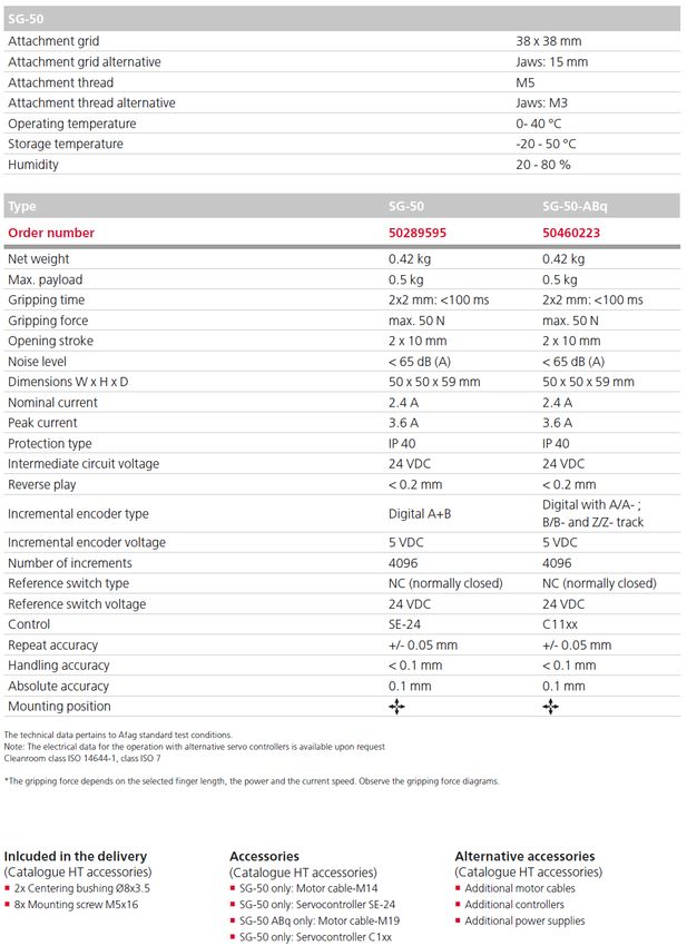
Dear Customer,
Thank you for choosing our products and placing your trust and confidence in
our company!
These assembly and operating instructions contain all essential information you
need about your product. Our aim is to provide the required information as
concisely and clearly as possible. If, however, you still have any questions on
the contents or suggestions, please do not hesitate to contact us. We are always
grateful for any feedback.
Our team will also be glad to answer any further question you may have
regarding the servo gripper or other options.
We wish you every success with our products!
With kind regards
Your Afag team
© Subject to modifications
The modules have been designed by Afag Automation AG according to the state
of the art. Due to the constant technical development and improvement of our
products, we reserve the right to make technical changes at any time.
© Copyright 2021 Afag Automation AG
All contents of the present assembly and operating instructions, in particular the
texts, photographs and graphics, are protected by copyright. All rights reserved.
No part of these assembly and operating instructions may be reproduced,
distributed (made available to third parties), or transmitted in any form or by any
means, including photocopying, recording, or other electronic or mechanical
methods, without the prior written permission of Afag Automation AG.
Afag Automation AG
Fiechtenstrasse 32
CH - 4950 Huttwil (Switzerland)
Tel.: +41 62 959 86 86
Fax.: +41 62 959 87 87
e-mail: sales@afag.com
Internet: www.afag.com
2 – 40 Assembly instructions EN SG-50 Edition 01/2021 Rev. 2.0
Table of contents
Table of contents
1 General .................................................................................................................... 5
1.1 Contents and purpose of these assembly instructions ................................. 5
1.2 Explanation of symbols................................................................................. 5
1.3 Additional symbols ........................................................................................ 6
1.4 Applicable documents .................................................................................. 7
1.5 Warranty ....................................................................................................... 7
1.6 Liability .......................................................................................................... 7
2 Safety instructions ................................................................................................. 8
2.1 General ......................................................................................................... 8
2.2 Intended use ................................................................................................. 8
2.3 Foreseeable misuse ..................................................................................... 8
2.4 Obligations of the operator and the personnel ............................................. 9
2.4.1 Observe the assembly instructions ........................................................ 9
2.4.2 Obligations of the operating company.................................................... 9
2.4.3 Obligations of the personnel ................................................................ 10
2.5 Personnel requirements ............................................................................. 10
2.5.1 Personnel qualification ......................................................................... 10
2.6 Personal protective equipment (PPE) ........................................................ 11
2.7 Changes and modifications ........................................................................ 11
2.8 General hazards / residual risks ................................................................. 12
2.8.1 General hazards at the workplace ....................................................... 12
2.8.2 Danger due to electricity ...................................................................... 13
2.8.3 Danger due to strong magnetic fields. ................................................. 13
2.8.4 Danger due to high temperatures ........................................................ 13
2.8.5 Mechanical hazards ............................................................................. 13
3 Technical data ...................................................................................................... 14
3.1 Dimensional drawing SG-50 ....................................................................... 14
3.2 Technical data SG -50 ................................................................................ 15
3.3 Preferred combinationsSG-50 .................................................................... 16
3.4 Gripping force diagram ............................................................................... 17
3.5 Gripper jaws maximum loads SG-50 .......................................................... 17
4 Transport, Packaging and Storage .................................................................... 18
4.1 Safety instructions for transport .................................................................. 18
4.2 Scope of supply .......................................................................................... 18
4.3 Transport .................................................................................................... 19
4.4 Packaging ................................................................................................... 19
4.5 Storage ....................................................................................................... 19
5 Design and description ....................................................................................... 20
5.1 Design of servo gripper .............................................................................. 20
5.2 Product description ..................................................................................... 20
Assembly instructions EN SG-50 Edition 01/2021 Rev. 2.0 3–40
Table of contents
5.3 Accessories ................................................................................................ 21
6 Installation, assembly & setting ......................................................................... 22
6.1 Safety Instructions for Installation & assembly ........................................... 22
6.2 Assembly & attachment .............................................................................. 23
6.2.1 Mounting holes ..................................................................................... 23
6.2.2 Tightening torques................................................................................ 23
6.3 Manufacture of the gripper fingers ............................................................. 24
6.4 Reference position...................................................................................... 25
6.5 Pin assignment SG-50................................................................................ 25
7 Commissioning .................................................................................................... 26
7.1 Safety instructions for commissioning ........................................................ 26
7.2 Preparatory activities for commissioning .................................................... 27
7.3 First commissioning .................................................................................... 27
7.4 Manual operation ........................................................................................ 28
7.5 Setup & retrofitting - Parametrization of the positions ................................ 28
7.5.1 Basics of gripping movements ............................................................. 28
7.5.2 Positioning mode .................................................................................. 29
7.5.3 Current mode ....................................................................................... 29
7.5.4 Further notes on settings ..................................................................... 30
8 Fault elimination................................................................................................... 31
8.1 Safety instructions for troubleshooting ....................................................... 31
8.2 Fault causes and remedy ........................................................................... 32
9 Maintenance and Repair ...................................................................................... 33
9.1 General notes ............................................................................................. 33
9.2 Safety instructions for Maintenance and repair .......................................... 33
9.3 Maintenance activities and maintenance intervals ..................................... 33
9.3.1 Overview of the maintenance points .................................................... 34
9.3.2 Further maintenance ............................................................................ 34
9.4 Spare parts and repair work ....................................................................... 34
10 Decommissioning, disassembly, disposal ........................................................ 35
10.1 Safety instructions for decommissioning and disposal ............................... 35
10.2 Decommissioning ....................................................................................... 35
10.3 Disposal ...................................................................................................... 35
11 Declaration of incorporation ............................................................................... 36
4 – 40 Assembly instructions EN SG-50 Edition 01/2021 Rev. 2.0
General
1 General
1.1 Contents and purpose of these assembly instructions
These assembly instructions contain important information on assembly,
commissioning, functioning and maintenance of the servo gripper to ensure safe
and efficient handling and operation.
Consistent compliance with these assembly instructions will ensure:
permanent operational reliability of the servo gripper,
optimal functioning of the servo gripper,
timely detection and elimination of defects (thereby reducing maintenance
and repair costs),
prolongation of the servo grippers’ service life.
The illustrations in this manual shall provide you with a basic understanding of
the module and may vary from the actual design of your module.
1.2 Explanation of symbols
The safety notes are marked by a pictogram and a signal word. The safety notes
describe the extent of the hazard.
DANGER
Danger!
This safety note indicates an imminently hazardous situation which, if not
avoided, will result in death or serious injury.
WARNING
Warning!
This safety note points out a potentially hazardous situation which, if not
avoided, could result in death or serious injury.
CAUTION
Caution!
This safety note points out a potentially dangerous situation which, if not
avoided, can result in minor or slight injuries.
NOTICE
This safety note points out a potentially dangerous situation which, if not
avoided, can cause substantial damage to property and the environment.
This note contains important additional information as well as useful tips for
safe, efficient and trouble-free operation of the servo gripper.
Assembly instructions EN SG-50 Edition 01/2021 Rev. 2.0 5–40
General
Further warning signs:
Where applicable, the following standardised symbols are used in this manual
to point out the various potential health risks.
Warning - Dangerous electrical voltage.
Warning - Risk of injury from contact with hot surfaces.
Warning - Risk of hand and finger injury due to uncontrolled
movements of components.
Warning - Magnetic field
Warning - back injury due to heavy lifting.
Warning - Risk of injury as a result of parts being flung out!
Warning -high noise levels
1.3 Additional symbols
In these assembly instructions the following symbols are used to highlight
instructions, results, references, etc..
Symbol Description
1. Instructions (steps ...)
Results of actions
References to sections
Enumerations not ordered
6 – 40 Assembly instructions EN SG-50 Edition 01/2021 Rev. 2.0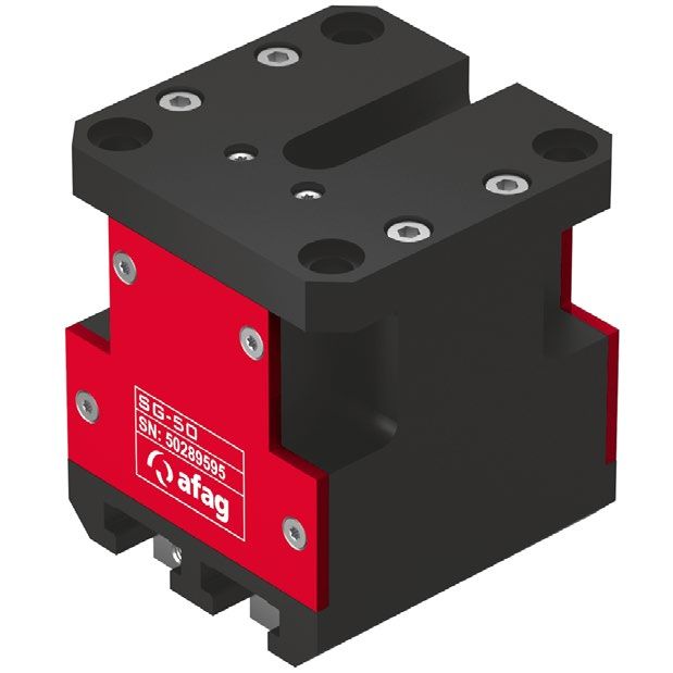
General
1.4 Applicable documents
Each servo gripper is accompanied by a safety information sheet. This
information sheet must be read carefully by every person who carries out work
on and with the servo gripper.
1.5 Warranty
The warranty terms for Afag handling components and handling systems are
the following:
24 months from initial operation and up to a maximum of 27 months from
delivery.
Wear parts are excluded from the warranty (The customer is entitled to a
product free of defects. This does also apply to defective accessories and
wear parts. Normal wear and tear are excluded from the warranty.
The warranty covers the replacement or repair of defective Afag parts. Further
claims are excluded.
The warranty shall expire in the following cases:
Improper use of the module.
Non-observance of the instructions regarding assembly, commissioning,
operation and maintenance of the module.
Improper assembly, commissioning, operation and maintenance.
Repairs and design changes carried out without prior technical instructions
of Afag Automation AG.
Removing the serial number from the product.
Inadequate checking of wear parts.
Non-observance of the EC Machinery Directive, the Accident Prevention
Regulations, the Standards of the German Electrotechnology Association
(VDE) and these safety and assembly instructions.
1.6 Liability
No changes shall be made to the servo gripper unless described in this
instructions manual or approved in writing by Afag Automation AG.
Afag Automation AG accepts no liability for unauthorized changes or improper
assembly, installation, commissioning, operation, maintenance or repair work.
Assembly instructions EN SG-50 Edition 01/2021 Rev. 2.0 7–40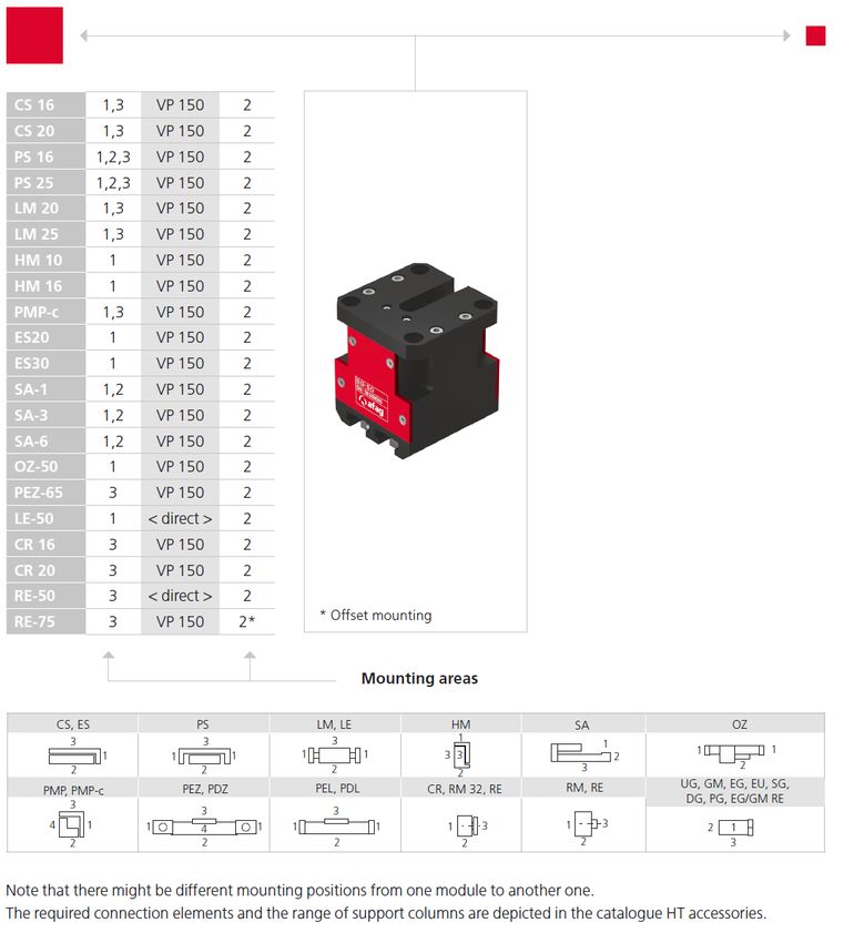
Safety instructions
2 Safety instructions
2.1 General
This chapter provides an overview of all important safety aspects to ensure safe
and proper use of the servo gripper and optimal protection of personnel.
Safe handling and trouble-free operation of the servo gripper requires
knowledge of the basic safety regulations.
Every person carrying out installation, commissioning, maintenance work or
operating the servo gripper must have read and understood the complete user
manual, especially the chapter on safety instructions.
Beyond this, there are rules and regulations regarding accident prevention that
are applicable to the place of installation which must be observed.
Improper use may result in danger to life and limb of the user or third parties or
in damage to the automation system or other material assets.
Failure to follow the directions and safety instructions given in this instructions
manual may result in serious hazards.
2.2 Intended use
The SG servo gripper is intended for the shock-free gripping movement of loads
in non-hazardous and in the ambient and operating conditions defined for this
module (Chapter 3 Technical data).
The servo grippers are intended exclusively for gripping payloads up to 0.5 kg
that do not pose any danger to persons, property or the environment during
manipulation (see also Chapter 5.2 Product description).
Any use beyond the described purpose is considered to be not in accordance
with the intended use.
The intended use of the module also includes:
observance of all instructions given in this instructions manual,
compliance with the inspection and maintenance work and the
specifications in the data sheets,
using only original spare parts.
2.3 Foreseeable misuse
Any use other than or beyond the intended use described above is considered
a misuse of the servo gripper.
Especially the following use is considered a misuse:
Use in potentially explosive atmospheres
8 – 40 Assembly instructions EN SG-50 Edition 01/2021 Rev. 2.0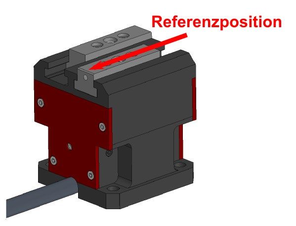
Safety instructions
WARNING
Risk of injury if the module is not used as intended!
The improper use of the servo gripper poses a potential hazard to the
personnel.
The servo gripper may only be used in a technically perfect condition in
accordance with its intended use and the instructions in this manual as well
as in compliance with the safety requirements!
Any malfunctions, particularly those that could impair safety, must be
eliminated immediately!
Risks can occur if the module is not used as intended. In the event of
damages caused by improper use the following shall apply:
the operating company shall be solely responsible for such damage, and
Afag does not accept any liability for damage caused by improper use.
2.4 Obligations of the operator and the personnel
2.4.1 Observe the assembly instructions
A basic prerequisite for safe and proper handling of the servo gripper is a good
knowledge of the basic safety instructions.
These assembly instructions, in particular the safety instructions contained
therein, must be observed by all persons working with the servo gripper.
2.4.2 Obligations of the operating company
In addition to the safety instructions given in this manual, the operating company
must comply with the safety, accident prevention and environmental protection
regulations valid for the field of application of the servo gripper.
The operating company is required to use only personnel who:
have the necessary professional qualifications and experience,
are familiar with the basic rules regarding occupational safety and accident
prevention,
have been instructed in the correct handling of the servo gripper,
have read and understood these assembly instructions.
The operating company is also required to:
monitor on an ongoing basis that the personnel work safely considering any
potential hazard involved and the assembly instructions are observed,
ensure that the assembly instructions are always kept at hand at the
installation in which the modules are mounted,
observe and communicate universally applicable laws and regulations
regarding accident prevention and environmental protection,
provide the necessary personal protective equipment (e.g. protective
gloves) and instruct the personnel to wear it.
Assembly instructions EN SG-50 Edition 01/2021 Rev. 2.0 9–40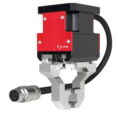
Safety instructions
2.4.3 Obligations of the personnel
All personnel working with the servo gripper are required to:
read and observe these assembly instructions, especially the chapter on
safety,
observe the occupational safety and accident prevention regulations,
observe all safety and warning signs on the servo gripper,
refrain from any activity that might compromise safety and health.
In addition, the personnel must wear the personal protective equipment
required for carrying out their work (Chapter 2.6).
2.5 Personnel requirements
2.5.1 Personnel qualification
The activities described in the assembly instructions require specific requisites
at the level of professional qualifications of the personnel.
Personnel not having the required qualification will not be able to asses the risks
that may arise from the use of the servo gripper thus exposing himself and
others to the risk of serious injury. Therefore, only qualified personnel may be
permitted to carry out the described activities on the servo gripper.
Persons whose ability to react is restricted due to the intake of medication or the
like must not interact with the servo gripper.
These installation instructions are intended for skilled personnel (installers,
system integrators, maintenance personnel, technicians), electricians and
operating personnel.
The following is a description of the professional skills (qualifications) required
for carrying out the different activities:
Qualified personnel:
Qualified personnel with appropriate training who are qualified due to their
special know-how and fully familiar with the machine and who have been given
instructions on how to carry out the task entrusted to them safely.
Qualified electrician:
Persons who have obtained their electrical qualifications through appropriate
professional training and complementary courses that enables them to identify
risks and prevent possible hazards resulting from electricity.
Operator (trained personnel):
Authorized persons who due to their specialized professional training,
expertise and experience are capable of identifying risks and preventing
possible hazards arising from the use of the machine.
10 – 40 Assembly instructions EN SG-50 Edition 01/2021 Rev. 2.0Safety instructions
2.6 Personal protective equipment (PPE)
The personal protective equipment serves to protect the personnel from hazards
affecting their safety and health at work.
When working on/with the servo gripper, the personnel must wear the personal
protective equipment assigned by the safety officer of the operating company or
as required by safety regulations. In addition, the personnel are required to:
wear the personal protective equipment provided by the operating company
(employer),
check the personal protective equipment for proper condition, and
immediately notify the person responsible on site of any defects found on the
personal protective equipment.
Personal protective equipment and the respective mandatory signs:
Protective clothing is a close-fitting clothing specifically
designed to protect personnel from hazards during work.
Protective gloves are specifically designed to protect the
personnel against hand injuries (such as cuts, abrasion,
burns).
Safety shoes are specifically designed to protect the
personnel against foot injuries from crushing, falling objects or
slipping on slippery surfaces.
Hearing protectors are required to protect the personnel
against excessive noise levels to prevent noise-induced
hearing loss.
2.7 Changes and modifications
No changes may be made to the servo gripper which have not been described
in these assembly instructions or approved in writing by Afag Automation AG.
Afag Automation AG accepts no liability for unauthorised changes or improper
assembly, installation, commissioning, maintenance or repair work.
The servo gripper may not be changed or modified in any way, except with
the prior written consent of Afag Automation AG.
Assembly instructions EN SG-50 Edition 01/2021 Rev. 2.0 11–40Safety instructions
2.8 General hazards / residual risks
Despite the safe design of the servo gripper and the technical protective
measures taken, there still remain residual risks that cannot be avoided and
which present a non-obvious residual risk when operating the servo gripper.
Observe the safety instructions in this chapter and in the other sections of this
manual to avoid damage to property and dangerous situations for the personnel.
2.8.1 General hazards at the workplace
The servo gripper has been built according to the state-of-the-art and the
applicable health and safety requirements. However, improper use of the servo
gripper may cause the following hazards to the personnel:
danger to life and limb of the operator or third parties,
on the servo grippers themselves,
property damage.
Always keep the assembly instructions ready at hand at the workplace!
Please, also observe:
the general and local regulations on accident prevention and environmental
protection,
the safety information sheet for the servo gripper.
WARNING
Danger - Do not use in unsuitable environment!
The servo grippers are designed for use in non explosive atmospheres.
Do not use the servo gripper in potentially explosive atmospheres!
CAUTION
Risk of injuries due to uncontrolled parts movements!
When operating the servo gripper uncontrolled movements may occur which
can cause personal injury or property damage.
Only qualified personnel may work with or on the servo gripper.
Read the assembly instructions carefully before carrying out any work on
or with the servo gripper.
12 – 40 Assembly instructions EN SG-50 Edition 01/2021 Rev. 2.0Safety instructions
2.8.2 Danger due to electricity
DANGER
Danger! Risk of electric shock!
If work on electrical components is required, ensure that the work is carried
out properly, failure to do so will cause serious or fatal injuries.
Work on the machine's electrical equipment may only be performed by
skilled electrician or trained personnel under the supervision of a skilled
electrician in accordance with all relevant electrical regulations.
2.8.3 Danger due to strong magnetic fields.
DANGER
Danger due to strong magnetic fields.
Due to the strong magnetic fields, electronic devices such as pacemakers
can be disturbed or their function impaired.
Persons with a pacemaker must keep a safety distance of at least 50 cm.
2.8.4 Danger due to high temperatures
CAUTION
Danger of injury from hot surfaces.
During continuous operation of the servo gripper, the surface of the axis heats
up.
Before touching hot surfaces without protective gloves, make sure they
have cooled down to ambient temperature.
2.8.5 Mechanical hazards
CAUTION
Danger of injury by moving components!
Limbs can be crushed by moving components!
Work on and with the servo gripper may only be carried out by qualified
personnel.
Never reach into the system during normal operation!
Assembly instructions EN SG-50 Edition 01/2021 Rev. 2.0 13–40Technical data
3 Technical data
3.1 Dimensional drawing SG-50
Fig. 1 Dimensional drawing SG-50
14 – 40 Assembly instructions EN SG-50 Edition 01/2021 Rev. 2.0Technical data
3.2 Technical data SG-50
Assembly instructions EN SG-50 Edition 01/2021 Rev. 2.0 15–40Technical data
3.3 Preferred combinations SG-50
16 – 40 Assembly instructions EN SG-50 Edition 01/2021 Rev. 2.0Technical data
3.4 Gripping force diagram
3.5 Gripper jaws maximum loads SG-50
The values given are static values related to one jaw - starting from the centre
of gravity of the jaw.
Type Maximum load
Mx 22 Nm
My 9 Nm
Mz 17 Nm
Fz 150 N
Fy 100 N
Fig. 2 Maximum loads on gripper jaws
For multiple loads, the following also applies:
When parametrizing the force and dynamic values, observe the chapter
7.5 Setup & retrofitting - Parametrization of the positions!
Assembly instructions EN SG-50 Edition 01/2021 Rev. 2.0 17–40Transport, Packaging and Storage
4 Transport, Packaging and Storage
4.1 Safety instructions for transport
CAUTION
Risk of injury when unpacking the servo gripper!
The servo grippers are packed in the original packaging (cardboard box). If
handled incorrectly, the module may fall out of the box when unpacked and
cause limb injuries.
Carefully unpack the servo grippers.
Also observe the safety instructions in chap. 2 „Safety instructions“ in this
manual.
4.2 Scope of supply
In addition to the assembly and operating instructions, a safety information
sheet is enclosed with each servo gripper.
This information sheet must be read by every person who carries out work
with and on the servo gripper!
Fig. 3 The servo gripper has a weight of < 1 kg
Unt. SG-50
1x Module SG -50
2x Centering bushing ø 8x3.5
4x Fastening screws M5x16
1x Assembly & operating instructions
18 – 40 Assembly instructions EN SG-50 Edition 01/2021 Rev. 2.0Transport, Packaging and Storage
4.3 Transport
No liability can be assumed for damages caused by improper installation on
the part of the operating company.
The following conditions must be complied with for transport and storage:
Storage temperature: 0-50 °C
Relative air humidity: < 90%, non condensing
4.4 Packaging
The servo gripper is transported in the Afag Automation AG transport
packaging. If no Afag packaging is used, the servo gripper must be packed in
such a way that it is protected against shocks and dust.
NOTICE
Risk to the environment due to incorrect disposal of the packaging
material
Environmental damage can be caused by incorrect disposal of the packaging
material.
Dispose of the packaging material in an environmentally sensitive way in
accordance with the local environmental regulations.
4.5 Storage
If the servo gripper is stored for an extended period of time, observe the
following:
Store the servo gripper in the transport packaging.
Do not store the servo gripper outdoors or expose it to weather conditions.
The storage space must be dry and dust free.
Room temperature of the storage space: 0-50 °C.
Relative air humidity: < 90% non condensing.
Clean the servo gripper and protect the blank metal parts against corrosion
using the appropriate means.
Protect the servo gripper from dirt and dust.
Assembly instructions EN SG-50 Edition 01/2021 Rev. 2.0 19–40Design and description
5 Design and description
5.1 Design of servo gripper
Fig. 4 Design of the servo gripper
1. Drive housing 3. Connection cable
2. Jaw guide 4. Gripper finger (not included in delivery!)
The servo gripper SG-50 consists of the base body (Fig. 4, 1) in which the
electric motor is integrated. The precise gripper guide system is integrated in
the transition piece (Fig. 4, 2). The gripper drive is designed with a connection
cable (length 0.35 m) with 12-pin industrial plug.
The gripper fingers (Fig. 4) are not included in the scope of delivery, they are
made individually by the customer ( Chapter 6.3)!
5.2 Product description
The servo gripper SG-50 is a highly compact parallel gripper with object
recognition for gripping payloads weighing up to 0.5 kg.
The servo gripper is equipped with a 12-pin industrial connector (M17 or M19)
and is designed for operation with the AFAG servo controller SE-24, C11xx or
C12 xx.
Operation with other controllers is also possible. When using third-party
controllers, it must be ensured that the maximum gripping force of the servo
grippers is not exceeded.
In combination with other modules the servo grippers can be used as a pick &
place Station.
Due to its integrated measuring function, the servo gripper can measure parts
during the gripping process. This function can be used for quality control or
sorting of parts.
20 – 40 Assembly instructions EN SG-50 Edition 01/2021 Rev. 2.0Design and description
5.3 Accessories
No. Designation Order Number
1 Centering bushing Ø 5x2.5mm 50035831
2 Centering bushing Ø 8x3.5mm 50263565
3 Servo controller C1100 CanOpen STO 50419402
4 Servo controller C1150 EtherCat STO 50419403
5 Servo controller C1150 Profinet PN STO 50419404
6 Servo controller SE-24 I/O 50315434
7 Servo controller SE-24 Profibus 50315435
8 Servo controller SE-24 EtherCAT 50315436
9 Servo controller SE-24 CANopen 50315437
10 Motor cable M14-3m-0-0 50311491
11 Motor cable M14-5m-0-0 50341510
12 Power cable SE-24/SE-48, 5m 50118124
13 Power cable SE-24/SE-48, 10m 50235739
14 Programming cable SE-24, 3m 50315431
15 I/O Cable SE-24, 5m 50312913
16 I/O Cable SE-24, 10m 50342940
17 SE-24 Stick 50315432
Assembly instructions EN SG-50 Edition 01/2021 Rev. 2.0 21–40Installation, assembly & setting
6 Installation, assembly & setting
The system operator is responsible for the installation of the servo gripper in
a system!
No liability for damages can be assumed for damages caused by improper
installation/assembling work on the part of the operator.
6.1 Safety Instructions for Installation & assembly
The servo gripper is an incomplete machine. For safe operation, the servo
grippers must be integrated into the safety concept of the system in which they
are installed.
During normal operation, it must be ensured that the user cannot interfere with
the working area of the servo gripper. This can be achieved by suitable
protective measures such as enclosures, light grids or disconnecting the drive
from the power supply.
When the system is running in special operating modes, it must be ensured that
there is no danger to the operator.
CAUTION
Risk of injury due to mounted components!
The jaws of the servo grippers are controlled electrically. Attachments can
restrict the free movement of the jaws of the servo gripper and cause injuries
such as crushing.
Make sure that the movement of the servo gripper is not restricted by
mounted attachments.
Take appropriate measures to ensure safe operation!
CAUTION
Risk of injuries due to uncontrolled parts movements!
Signals from the control system can trigger unintentional movements of the
servo gripper, which can cause injury.
When working on the servo gripper, switch off the controller and secure it
against unintentional restart.
Also observe the safety instructions in Chapter 2 „Safety instructions“ in
this manual.
22 – 40 Assembly instructions EN SG-50 Edition 01/2021 Rev. 2.0Installation, assembly & setting
6.2 Assembly & attachment
The servo grippers can be mounted both in horizontal and vertical position.
6.2.1 Mounting holes
The module is attached to the rear of the housing plate.
Fig. 5 Mounting holes on the housing - 4 x Ø 5.3 mm
Use the centring bushings ( Chapter 4.2) included in the scope of delivery
for positioning.
Insert the centering bushings into two diagonally opposite holes of the
attachment grid.
6.2.2 Tightening torques
For assembling use screws with the following minimum specifications:
Standard VDI 2230
Screw strength Category 8.8
Surface: Galvanized blue, oiled or greased
Thread Tightening torque
M2 0.3 … 0.35 Nm
M2.5 0.5 … 0.73 Nm
M3 1.1 … 1.4 Nm
M4 2.6 … 3.3 Nm
M5 5.2 … 6.5 Nm
M6 9.0 … 11.3 Nm
M8 21.6 … 27.3 Nm
Assembly instructions EN SG-50 Edition 01/2021 Rev. 2.0 23–40Installation, assembly & setting
6.3 Manufacture of the gripper fingers
For most applications the gripper fingers’ design can be symmetrical.
Example for the manufacturing of a gripper finger:
Fig. 6 Example for manufacturing the gripper fingers
AFAG does not manufacture standard gripper fingers. Gripping fingers are
therefore not included in the scope of delivery.
The gripper fingers must be designed and manufactured by the operator!
24 – 40 Assembly instructions EN SG-50 Edition 01/2021 Rev. 2.0Installation, assembly & setting
6.4 Reference position
The gripper fingers and attachments of the servo gripper must be designed so
that the reference position can be approached.
This is only guaranteed if the jaw side with chamfer and the lateral fastening
thread can move up to the housing edge of the gripper.
Reference position
= Gripper open
Adjust the manual control only in de-
energized status ( Chapter 7.4)
Fig. 7 Reference position servo gripper
6.5 Pin assignment SG-50
Pin Value
1 GND
2 VDD 5 V
3 B
4 A
5 PE
6 Z
7 Sensor GND
8 Sensor V+ 24 V
9 Sensor NC
10 U
11 V
12 W
Fig. 8 Pin assignment servo gripper SG-50
Assembly instructions EN SG-50 Edition 01/2021 Rev. 2.0 25–40Commissioning
7 Commissioning
After connection, the servo grippers are put into operation for the first time via
the system controller.
7.1 Safety instructions for commissioning
CAUTION
Risk of injury due to mounted components!
The jaws of the servo grippers are controlled electrically. Attachments can
restrict the free movement of the jaws of the servo gripper and cause injuries
such as crushing.
Make sure that the movement of the servo gripper is not restricted by
mounted attachments.
Take appropriate measures to ensure safe operation!
CAUTION
Danger of injury in the working area of the servo gripper!
Due to the decentralised control system, the operator of the servo gripper
must not necessarily stand next to the module during operation so that he
may not have a complete view of the working area. Persons in the working
area may be injured.
When operating the servo gripper, ensure a good overview of the entire
working area.
Unauthorized persons must not stay within the working area during
operation.
CAUTION
Risk of injuries due to uncontrolled parts movements!
Signals from the control system can trigger unintentional movements of the
servo gripper, which can cause injury.
When working on the servo gripper, switch off the controller and secure it
against unintentional restart.
Observe the safety instructions in Chapter 2 „Safety instructions“ of these
assembly instructions!
26 – 40 Assembly instructions EN SG-50 Edition 01/2021 Rev. 2.0Commissioning
7.2 Preparatory activities for commissioning
The servo gripper is designed for operation with the AFAG servo controller SE-
24. However, the servo gripper can also be operated with other controllers. The
required characteristic data will be provided on request.
The operation of the SE-24 servo controller is described in a separate manual.
Fig. 9 Servo gripper SG-50 with cable and servo controller SE-24
To prepare for commissioning proceed as follows:
1. Connect the servo gripper to the SE-24 servo controller using the M14 motor
cable (Fig. 9).
- Motor cable contains motor conductors, encoder conductors and ref.
conductors.
2. Connect the servo controller to the power supply.
- A supply cable is available for the AFAG Se-24 servo controller
( Section 5.3 Accessories).
3. For test operation, connect the servo controller to a computer (operating
software must be installed on the computer). Observe the operating
instructions for the servo controller.
If the SG-50 servo gripper is supplied in combination with an AFAG servo
controller, the operating parameters are already stored in the servo
controller. The servo gripper can be operated immediately.
If the SG-50 servo gripper is operated with an alternative servo controller,
the operator must make special cables and determine the appropriate
operating parameters.
For gripping the parts to be handled, the gripper fingers must be
manufactured by the operator ( Chap. 6.3 Manufacturing the gripper
fingers).
7.3 First commissioning
Proceed carefully and follow the instructions step by step when commissioning
the modules for the first time:
1. Observe the permissible technical values ( Chapter 3).
- Payload, movement frequency and moment load
2. First, make sure that there are no persons or tools in the working area.
3. Perform test run:
- Start with slow movements
- Then continue under normal operating conditions
Commissioning is completed.
Assembly instructions EN SG-50 Edition 01/2021 Rev. 2.0 27–40Commissioning
7.4 Manual operation
The manual control is used to pre-set the gripper fingers or the gripper position.
In addition, the manual control is used to release the blocked gripper jaws in the
open-end position.
Turn screw counterclockwise
(= close gripper jaws)
Fig. 10 Manual operation servo gripper
Adjustment of the manual control only in de-energized state!
7.5 Setup & retrofitting - Parametrization of the positions
When carrying out set-up work on the servo gripper, the controller enable
must be deactivated and only switched on again after the work has been
completed!
Observe safety instructions!
7.5.1 Basics of gripping movements
Basically, two different modes can be selected for each individual movement on
the gripper:
Positioning mode and
current or force mode
Each mode is optimized for one movement. The current mode must always be
used when gripping and the positioning mode when opening the gripper.
Due to the self-locking spindle, which prevents displacement of the gripper jaws
in the de-energized state, the dynamics of the gripping/opening movement must
be coordinated.
28 – 40 Assembly instructions EN SG-50 Edition 01/2021 Rev. 2.0Commissioning
7.5.2 Positioning mode
The positioning mode is used when moving to a specific position. This is typically
the case when a part is released, or the gripper fingers are pre-positioned.
The positioning mode is active if the hook for current [%] is not set or the "Mode"
signal via the bus is not activated (Fig. 11).
Fig. 11 Positioning mode servo gripper
The following must always be observed in positioning mode:
The position must always be within the maximum position limits (between
1000 and 21,000 µm).
If possible, the module should not be displaced to the position limits.
A position selection between 0 µm and 20,000 µm is recommended.
7.5.3 Current mode
Current mode is used when driving on block. This is typically the case when a
part is gripped.
The current mode is active when the check mark for current [%] is set or the
"Mode" signal is activated via the bus (Fig. 12).
Fig. 12 Current mode servo gripper
The following should always be observed in the current mode:
The setting range for the current is between 20% and 100%.
After the gripping movement, you can see whether a part has been gripped.
For this purpose, the target position of the gripping movement must be
selected in such a way that the fingers do not close completely when no part
is present.
If a part is gripped and thus the parametrized current value is reached, the
controller sets the signal "move_ok".
If no part is present, the gripper reaches the parametrized target position, but
not the parametrized current value.
- The controller does not set the signal "move_ok".
Assembly instructions EN SG-50 Edition 01/2021 Rev. 2.0 29–40Commissioning
In current mode, it is important that the current default value is set as low as
possible. This enables a higher dynamic in the positioning mode.
In addition, it saves electricity and protects the mechanics, which also leads
to an extension of the service life.
For positive gripping, a current value of 20% is usually sufficient.
A higher current value may be necessary for force-locking gripping.
- This should be chosen as low as possible (20%).
7.5.4 Further notes on settings
A more sensitive response and a greater process reliability of the force
evaluation can be achieved by lower displacement speeds. This applies in
particular to small gripping forces.
For time-critical applications, fast pre-positioning outside the maximum
dimensions of the gripping part and subsequent gripping at low speed is
recommended.
The gripping force corresponding to the percentage default value can change
over time due to changing friction and wear influences. This must therefore be
checked regularly and readjusted if necessary.
When operating with alternating internal and external gripping, the existing
backlash must be taken into account for more accurate measurement. This may
increase slightly over time due to wear.
Excessive and long holding of the force (in force mode) overheats the servo
gripper!
The maximum forces can only be applied for a short time!
30 – 40 Assembly instructions EN SG-50 Edition 01/2021 Rev. 2.0Fault elimination
8 Fault elimination
8.1 Safety instructions for troubleshooting
WARNING
Danger of injury due to faulty troubleshooting!
Poorly performed troubleshooting work can lead to serious injuries and
damage to property.
Only use trained specialist personnel for troubleshooting.
All work on the servo gripper must be carried out with the power supply
cut off!
CAUTION
Risk of injury due to mounted components!
The jaws of the servo grippers are controlled electrically. Attachments can
restrict the free movement of the jaws of the servo gripper and cause injuries
such as crushing.
Make sure that the movement of the servo gripper is not restricted by
mounted attachments.
Take appropriate measures to ensure safe operation!
CAUTION
Danger of injury in the working area of the servo gripper!
Due to the decentralised control system, the operator of the servo gripper
must not necessarily stand next to the module during operation so that he
may not have a complete view of the working area. Persons in the working
area may be injured.
When operating the servo gripper, ensure a good overview of the entire
working area.
Unauthorized persons must not stay within the working area during
operation.
Also observe the safety instructions in chap. 2 „Safety instructions“ in this
manual.
Assembly instructions EN SG-50 Edition 01/2021 Rev. 2.0 31–40Fault elimination
8.2 Fault causes and remedy
The following table contains an overview of possible fault causes and how to
proceed to eliminate them.
Fault Possible cause Remedy:
Jaws do not move Servo gripper incorrectly Check the connection of the servo
connected gripper to the controller
Jaws in mechanical end stop Releasing the jaws using the servo
blocked by the spindles gripper manual adjustment
( chapter 7.5.3)
Controller not connected to Check the power supply of the
power supply controller
Communication error to the Check bus connection / I/O
controller connection of the controller
Gripping force decreases / Dirt deposits/ dry running of the Clean servo gripper / lubricate
servo gripper opens and guides sliding guides with suitable grease
closes abruptly
32 – 40 Assembly instructions EN SG-50 Edition 01/2021 Rev. 2.0Maintenance and Repair
9 Maintenance and Repair
9.1 General notes
The servo grippers are almost maintenance-free. Nevertheless, some
maintenance work must be carried out to ensure an optimum operating
condition of the modules.
9.2 Safety instructions for Maintenance and repair
WARNING
Danger of injury due to improper maintenance!
Improperly carried out maintenance activities can cause considerable
damage to property and serious injury.
Only use trained specialist personnel to carry out the activities.
Always wear personal protective equipment when carrying out maintenance
and repair work!
WARNING
Risk of injuries due to uncontrolled parts movements!
Signals from the control system can trigger unintentional movements of the
servo grippers, which can cause injury.
Before starting any work on the servo gripper, switch off the control unit and
secure to prevent it from being switched on.
Observe the operating instructions of the controller used!
Also observe the safety instructions in chap. 2 „Safety instructions“ in this
manual.
9.3 Maintenance activities and maintenance intervals
Observe the specified maintenance and care intervals. The intervals refer
to a normal operating environment.
Assembly instructions EN SG-50 Edition 01/2021 Rev. 2.0 33–40Maintenance and Repair
9.3.1 Overview of the maintenance points
Fig. 13 Servo gripper maintenance points SG-50
System
No. Maintenance point Maintenance work Interval Remarks
[On/Off]
1 Servo gripper module Cleaning and As required [Off] -
checking
Clean the servo gripper with a dry, lint-free cloth.
- Do not spray the module with water, do not use
aggressive cleaning agents.
- Perform a visual inspection of the servo gripper.
9.3.2 Further maintenance
Further maintenance is not required, if the ambient conditions listed below are
complied with:
Clean working area
No use of splash water
No abrasion or process dusts
Environmental conditions as specified in the technical data
9.4 Spare parts and repair work
Afag Automation AG offers a reliable repair service. Defective servo grippers
can be sent to AFAG for warranty repair within the warranty period.
Damaged servo grippers may only be replaced or repaired by Afag
Automation AFAG! No spare parts are available for the servo grippers.
CAUTION
Danger of injury when dismounting the servo gripper!
When disassembling the servo grippers from a system, there is a danger of
uncontrolled movements.
Only remove the servo gripper when the control unit is switched off and
secured!
Only remove the servo gripper when the control unit is switched off and
secured!
34 – 40 Assembly instructions EN SG-50 Edition 01/2021 Rev. 2.0Decommissioning, disassembly, disposal
10 Decommissioning, disassembly, disposal
The servo gripper must be properly dismantled after use and disposed of in an
environmentally friendly manner.
10.1 Safety instructions for decommissioning and disposal
WARNING
Risk of injury due to improper decommissioning and disposal!
Improperly carried out activities can result in considerable material damage
and serious injury.
Only use trained specialist personnel to carry out the activities.
Disconnect the media supply (electrics, pneumatics) before removing the
modules!
Only remove the servo gripper when the control unit is switched off and
secured!
10.2 Decommissioning
If the servo grippers are not used for a longer period of time, they must be
properly commissioned and stored as described in chapter 4.5.
10.3 Disposal
The servo gripper must be disposed of properly at the end of their service life
and the raw materials used must be recycled. Observe the legal regulations and
company requirements.
The servo gripper must not be disposed of as a complete unit. Dismantle the
servo gripper and separate the various components according to type of
material and dispose of them properly:
Scrap the metallic materials.
Hand over plastic parts for recycling.
Sort the rest of the components by their material properties and dispose of
them accordingly.
NOTICE
Risk to the environment due to incorrect disposal of the packaging
material of the servo gripper!
Environmental damage can be caused by improper disposal of the servo
gripper.
Electronic parts, electrical scrap, auxiliary and operating materials must
be disposed of by approved specialist companies.
Information on proper disposal can be obtained from the responsible local
authorities.
Assembly instructions EN SG-50 Edition 01/2021 Rev. 2.0 35–40Declaration of incorporation
11 Declaration of incorporation
Declaration of incorporation
for partly completed machinery according to the Machinery Directive 2006/42/EC, Annex II, 1.B
The manufacturer hereby declares:
Afag Automation AG, Fiechtenstrasse 32, CH-4950 Huttwil
that the partly completed machine:
Product description Servo gripper SG
Type: SG-50, SG-50 ABq
complies with the following essential health and safety requirements of the Machinery Directive 2006/42/EC
at the time of declaration: 1.1; 1.1.1; 1.1.2; 1.2; 1.2.1; 1.2.3; 1.2.4.4; 1.2.5; 1.3; 1.3.3; 1.3.5; 1.3.6; 1.3.7;
1.3.8.1; 1.3.8.2; 1.3.9; 1.4; 1.4.1; 1.5; 1.5.1; 1.6; 1.6.1; 1.6.3; 1.6.4; 1.7; 1.7.1; 1.7.4.; 1.7.4.1; 1.7.4.2; 1.7.4.3;
3.3.5; 3.4.1.
Harmonised standards applied, in particular:
2014/30/EU Electromagnetic Compatibility Directive (EMC)
2014/35/EU Low Voltage Directive (LVD)
EN ISO 12100:2010 Safety of machinery - General design principles - Risk assessment and risk
reduction.
DIN EN 60204-1:2018 Safety of machinery - Electrical equipment of machines - Part 1: General
requirements
Note: The partly completed machinery must not be put into service until the machinery into which it is to
be incorporated has been declared in conformity with the provisions of Machinery Directive
2006/42/EC.
The manufacturer undertakes to transmit, in response to a reasoned request by the national authorities,
relevant technical documentation for the partly completed machinery.
The relevant technical documentation has been created according to Annex VII, Part B of the above-
mentioned Directive.
Authorised representative for compiling the technical documentation:
Niklaus Röthlisberger, Product Manager, Afag Automation AG, CH-4950 Huttwil, Germany
Place/Date: Huttwil, 07.01.2020
Siegfried Egli Niklaus Röthlisberger
Managing Director
Product Manager
Afag Automation AG
36 – 40 Assembly instructions EN SG-50 Edition 01/2021 Rev. 2.0Declaration of incorporation
Index
A Operator ............................................................ 10
Axes and channels ............................................ 33 P
D Packaging ......................................................... 19
Personal protective equipment (PPE)............... 11
Decommissioning .............................................. 35
Personnel qualifications .................................... 10
Disposal ............................................................. 35
Personnel requirements .................................... 10
E
Protective clothing............................................. 11
Explanation of symbols ........................................ 5 Protective gloves............................................... 11
F Q
Foreseeable misuse ............................................ 8 Qualified electrician........................................... 10
G Qualified personnel ........................................... 10
Glossary of terms and list of abbreviations ......... 7 R
I Residual risks.................................................... 12
Instructions .......................................................... 6 S
O Safety instructions......................................... 8, 33
Obligations and liability ........................................ 9 Safety shoes ..................................................... 11
Obligations of the operating company ................. 9 Storage ............................................................. 19
Obligations of the personnel .............................. 10 System error ..................................................... 32
Operation ........................................................... 31
Assembly instructions EN SG-50 Edition 01/2021 Rev. 2.0 37–40List of figures Fig. 1 Dimensional drawing SG-50 ........................................................................................................... 14 Fig. 2 Maximum loads on gripper jaws...................................................................................................... 17 Fig. 3 The servo gripper has a weight of < 1 kg ........................................................................................ 18 Fig. 4 Design of the servo gripper ............................................................................................................. 20 Fig. 5 Mounting holes on the housing - 4 x Ø 5.3 mm .............................................................................. 23 Fig. 6 Example for manufacturing the gripper fingers ............................................................................... 24 Fig. 7 Reference position servo gripper .................................................................................................... 25 Fig. 8 Pin assignment servo gripper SG-50 .............................................................................................. 25 Fig. 9 Servo gripper SG-50 with cable and servo controller SE-24 .......................................................... 27 Fig. 10 Manual operation servo gripper ...................................................................................................... 28 Fig. 11 Positioning mode servo gripper....................................................................................................... 29 Fig. 12 Current mode servo gripper ............................................................................................................ 29 Fig. 13 Servo gripper maintenance points SG-50 ....................................................................................... 34 38 – 40 Assembly instructions EN SG-50 Edition 01/2021 Rev. 2.0
Assembly instructions EN SG-50 Edition 01/2021 Rev. 2.0 39–40
40 – 40 Assembly instructions EN SG-50 Edition 01/2021 Rev. 2.0
You can also read