Mio Move - SORG Rollstuhltechnik
←
→
Page content transcription
If your browser does not render page correctly, please read the page content below
Service Record Mio Move

                                                                               ENG

       Mio Move

                       Service Record
         In the following all individual adjustments of the wheelchair are
           described. These adjustments require tools and specialised
         knowledge. Please leave the adjustments to a qualified rehab
                                     consultant.
2021-05-26                  Service Record Mio Move   Unique people, unique solutions.
                                                                             1 of 32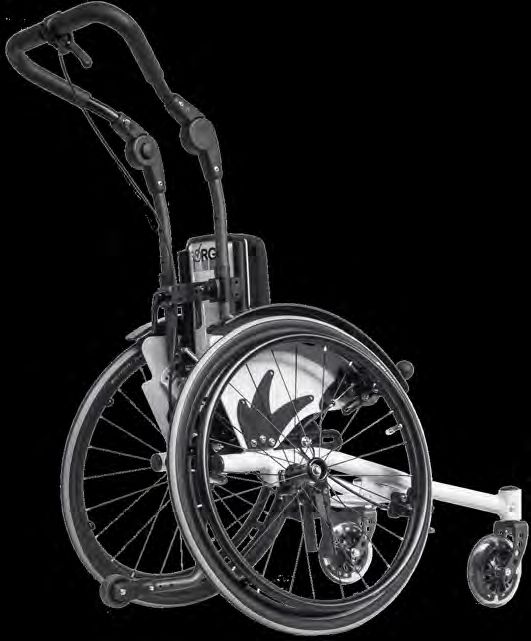
Imprint
SORG Rollstuhltechnik GmbH+Co.KG
Benzstraße 3-5
68794 Oberhausen-Rheinhausen / Germany
Tel. +49 7254-9279-0
Fax +49 7254-9279-10
E-Mail info@sorgrollstuhltechnik.de
Web www.sorgrollstuhltechnik.de
Revision status
2021-05-26
Technical status
Technical changes and misprints reserved. The
pictures in this Instructions for use can differ
from the actual equipment components. How-
ever, a corresponding conduction is possible.
Copyright
All texts, pictures and graphics underlie co-
pyright protection. All rights, including co-
pying, publishing, editing and translating,
remain reserved. © by SORG Rollstuhltech-
nik GmbH+Co. KG Benzstraße 3-5, 68794
Oberhausen-Rheinhausen / Germany.
Our terms and conditions can be found
on our order forms and at www.sorgrollstuhl-
technik.de/impressum.
2 of 32 Service Record Mio Move 2021-05-26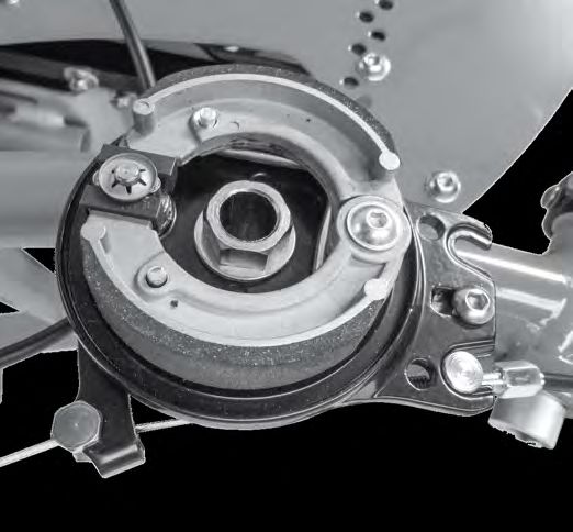
Table of content
     1 Wheelchair overview                                 4    4 Repairs/maintenance/reinstatement27
                                                                    4.1 Repairs                     27
     2 General information                                 5       4.2 Spare parts                 27
        2.1 General indications                            5       4.3 Maintenance                 27
        2.2 Documentation indications                      5       4.4 Disinfection                27
        2.3 Required torques and tools                     5       4.5 Storage                     27
        2.4 Explanation of symbols                         6       4.6 Lifespan                    28
        2.5 General safety instructions                    7       4.7 Reinstatement               28
                                                                    4.8 Disposal                    28
     3 Assembly groups                                       8      4.9 Maintenance/Inspection      28
        3.1 Assembly group wheels                           8
            3.1.1 Centre of gravity/ wheelbase              8   5 Technical specifications            30
            3.1.2 Camber                                    8      5.1 Data and measurements          30
            3.1.3 Casters                                   9      5.2 Meaning of labels              31
        3.2 Assembly group seat                            10      5.3 Declaration of conformity      31
            3.2.1 Tilting                                  10
            3.2.2 Changing the seat position               11
            3.2.3 Changing the seat width                  11
            3.2.4 Blocking the tilting                     11
        3.3 Assembly group back                            12
            3.3.1 Changing the back height                 12
            3.3.2 Replacing/ removing the curved back plate12
            3.3.3 Bracklet tabs for the curved back plate13
            3.3.4 Adjust back cover                        13
        3.4 Assembly group belt system                     14
            3.4.1 Displacing the bottom metal locks 14
            3.4.2 Displacing the top metal locks           14
            3.4.3 Height setting of the belt holders 15
        3.5 Assembly group leg support                     16
            3.5.1 Leg support standard                     16
            3.5.2 Foot plate can be elevated, divided 17
            3.5.3 Leg rest                                 17
        3.6 Assembly group side guards                     18
            3.6.1 Side guards                              18
        3.7 Assembly group brake                           19
           3.7.1 Wheel lock                                19
           3.7.2 Cable brake                               19
           3.7.3 Setting the length of the brake lever 20
           3.7.4 Drum brake                                20
        3.8 Assembly group anti-tipper                     22
            3.8.1 Adjust height                            22
        3.9 Assembly group truss pads                      23
            3.9.1 Classification                           23
            3.9.2 Vertical setting                         23
            3.9.3 Horizontal setting                       24
        3.10 Assembly group outdoor front end              25
            3.10.1 Settings                                25

2021-05-26                               Service Record Mio Move                                     3 of 32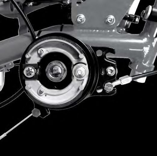
1 Wheelchair overview
1 push bail
1 2 back cushion
3 side guard
2 4 wheel cover
3 5 brake lever
6 seat cushion
4 7 seat plate
5 8 frame
9 leg support
10 caster fork
11 caster
12 brake block wheel lock
13 rear wheel
6 14 quick-release axle
7 15 hand rim
8
15 14 13 12 11 10 9
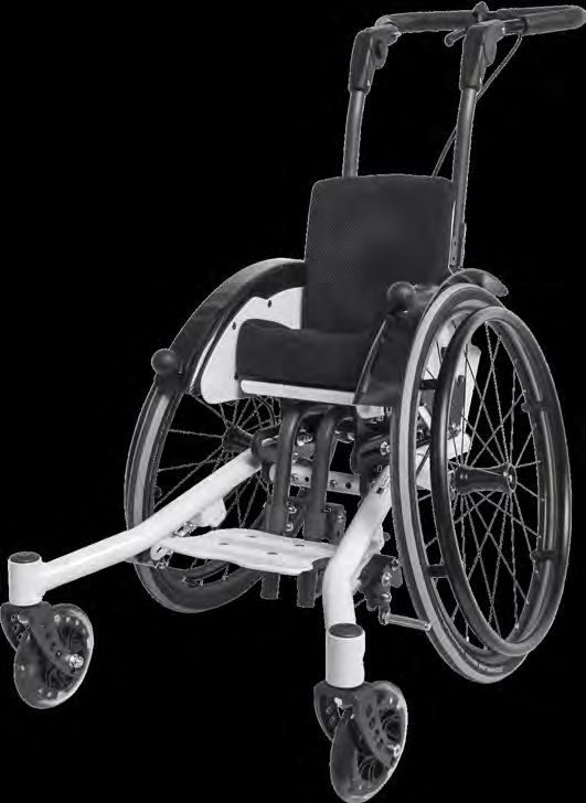
16
16 push bail
17 triggering lever tilt mechanism
17 18 angle adjustment
19 firm curved back plate
18 20 Eccentric tensioner for push bail
21 anti-tipper
19
20
21
4 of 32 Service Record Mio Move 2021-05-26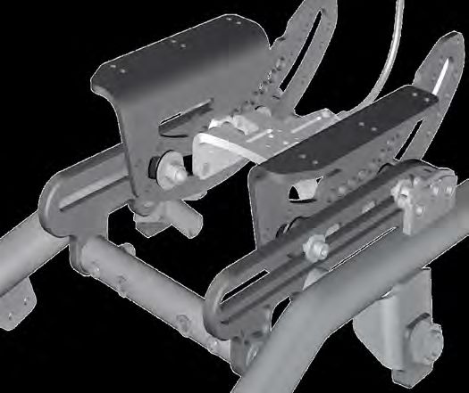
2 General information
      2.1 General indications

     In the following all individual settings, adjustments and repairs as well as the yearly inspection of
     the wheelchair are described. These adjustments require tools and specialised knowledge. Ple-
     ase leave the adjustments to a qualified rehab consultant.

     Should questions or suggestions come up then please contact your medical supply store or our
     team (+49 7254 9279-0).

      2.2 Documentation indications

     Please note:
        • Information about before sale can be found in the instructions for use
        • Infomation for the user can be found in the instructions for use
        • For maintenance instructions see: Chapter 4 (Repair & Maintenance)

      2.3 Required torques and tools

      For the following screws needed torque:

        •    M5: 5 Nm;
        •    M6: 7 Nm;
        •    M6 (axle plate) 10 Nm
        •    M8: 20 Nm;
        •    M10 (nut): 25 Nm; (caster)
        •    quick release axle fitting 40 Nm

      Needed tools:

        •    torque wrench (5-50 Nm)
        •    open end wrench
        •    flex ratchet handle with socket wrench inserts
        •    hexagon screw driver
        •    Phillips screw driver
        •    flat head screw driver
        •    plastic mallet
        •    side cutter
        •    threadlocker (fluid)
        •    bicycle inner tube repair kit
        •    work bench/jaw vise with rubber pads

2021-05-26                          Service Record Mio Move                                         5 of 32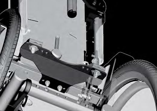
2 General information
   2.4 Explanation of symbols

                     ATTENTION! Warnings for perso-
                     nal Safety aspects that are of the                important detail
                     utmost importance.

                     CORRECT safety adjustment/ use                    correct or proper use/setting

                     WRONG adjustment/ use
                                                                       incorrect or improper use/setting

                     NOT ALLOWED                            (A); (B)   reference from text to detail

                     References to additional/conti-
                     nuing reading.

  Use

                     push/ pull/ insert / move/                        point of view

                     Push in specific direction                        view from top

                     Setting or adjusting the angle                    view from the side

                     open/ close                                       view from the bottom

                     Turn clockwise
                                                                       view from the front

                     Turn counter-clockwise
                                                                       view from the back
     1.         1.   steps to be done at the same
                     time
                                                                       fasten parts
      1.        2.   steps to be done after each other
           ;
                                                                       remove parts
           2x        steps to be done on both sides

6 of 32                                Service Record Mio Move                                         2021-05-26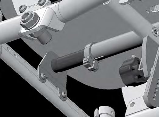
2 General information
      2.5 General safety instructions

             Before each use be sure to check:
        •     frame, back tubes, attachments and accessories for visible damage, bends, cracks or mis-
              sing/loose scews,
        •     wheels/quick release axles for firm fit,
        •     sufficient tire pressure, tire tread,
        •     functionality of the brakes,
        •     firm fit of the angle adjustment elements/ eccentric clamps,
        •     firm fit of the seat plate/ the back/ the foot plate,
        •     functionality of the anti-tipper/ seat and back straps,
        •     if all previously disassembled parts are re-inserted or firmly locked.

          There is a risk of injuries (e. g. such as bruising) on all rotating or folding parts, including
      adjustments, repairs and transport.

             All wheelchair parts are to be handled with care. Do not throw or drop removable parts.

           Before repairs or adjustments are made, clean/didinfect the wheelchair and secure it from
      tipping over and/or falling down.

             Only use original spare parts.

             Safety nuts may only be used once. Lossened safety nuts must be replaced by new ones.

          Only the regular maintenance of all safety-relevant parts on the wheelchair by a qualified
      rehab workshop protects against damage and maintains our manufacturer's warranty.

      Lifespan

            Use beyond the specified lifespan increases the residual risks and should only be carried
      out after careful, qualified consideration by the operator. If the useful life is reached, the user
      or a responsible person should contact the specialist dealer. There you can be informed about
      the possibility of reprocessing the product.

      Combination with products from other manufacturers

           The wheelchair may only be combined with the electrical auxiliary drives approved by the
      manufacturer. The responsibility of restrictions or adjustmens as well as the attachment itself
      lies with the supplier of the additional system or the specialized retailer. Please ask about the
      conditions with the manufacturer of the auxiliary drives.

           In combination of wheelchair and electric auxiliary drive, certain strains occur that can
      lead to damage to the wheelchair. Slowly approach abstacles and carefully overcome them so
      that little force is applied to the casters, rear wheels and the wheelchair as a whole.

2021-05-26                            Service Record Mio Move                                          7 of 32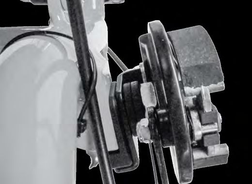
3.1 Assembly group wheels
    3.1.1 Centre of gravity/ wheelbase

  The center of gravity (degree of activity), the seat height and the seat angle of the wheelchair
  are used for wheelchairs of product group 18.50.03. usually set with the constellation drive and
  steering wheels or the perforated plate. The wheelbase is fixed on the Mio and can not be chan-
  ged. The center of gravity is adjusted via the seat support angle.

    3.1.2 Camber

  Variant till 31.12.2016:
  In order to change the camber remove the rear          (1)                     (B)
  wheels and secure the wheelchair from rolling
  away.
      • Completely remove the quick-release                                               (A)
         axle fitting (A) including the drum brake
         arm (B),
      • place the camber adjustment (C) on
         the rear wheel reception (D) (possible
         changes of camber about ± 2°to 7°or
         11° from horizontally turning the camber
         adjustment 180°),                                        (B)
      • replace quick-release axle fitting (A) in-          (C)
         cluding the drum brake arm (B), screw           (2)
         on tightly and
      • put wheels back on.
                                                                  min. 10 mm

                                                                                                   min. 10 mm
  (2) Check the distance of the rear wheel to the
  side guard by shortly placing the rear wheel on.

  (3) Correct the quick-release axle fitting and
  turn it as far in or out, that the wheels tire has a
  minimum distance of 10 mm to the side guard
  or the skirt guard.                                    (3)
      • Loosen nuts (A) and (B),
      • turn the quick-release axle adapter (C) in
          or out,
      • retighten the nuts (A) and (B) (tighten-
          ing torque nuts M18 fitting 35 Nm).
                                                               (A)                                 (C)
                                                               (B)

       After adjusting the quick-release axle adapter, be sure to check that the wheel lock functions
   properly.

          Make sure the distance of the quick-release fitting is the same on the left and right!

  The camber and toe adjustment from 01.01.2017 can be found in our service brochure Camber
  and toe compensation. This can be found at http://www.sorgrollstuhltechnik.de/

8 of 32                            Service Record Mio Move                                            2021-05-26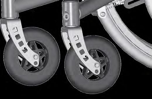
3.1 Assembly group wheels
      3.1.3 Casters
     The casters are tightly attached to the frame
     pipe and cannot be adjusted.                      (1)

     (1) To displace/replace the casters:
         • remove the screws (A) completely,
         • remove the husks,
         • change the casters,
         • if necessary, guide the husks and wheels
            in the new holes (B),
         • replace the safety nuts with new ones (!)
         • and retighten all the screws.                     (A)   (A)
                                                             (B)   (B)

2021-05-26                         Service Record Mio Move         9 of 32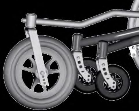
3.2 Assembly group seat
    3.2.1 Tilting

   You do not need to make any adjustments on           (1)
   the tilting mechanism of the Mio Move.               (C)
   (1) A list of names of the individual assembly                     (F)                (D)
   parts of the seat (the same parts are found mir-
                                                         (B)
   ror-inverted on the opposite side):                                                     (E)
       • (A) frame pipe
       • (B) tilting
       • (C) tilting slide
       • (D) release mechanism for locking bolt
       • (E) locking bolt for the tilting
       • (F) cap nut with screw heads

                                                               (C)
                                                              (B)                  (F)
                                                                (A)

    3.2.2 Changing the seat position
   (2+3) horizontal displacement                        (2)
   With a centered positioned seat you can change
   the seat position along the tilting bar (A) 4,5 cm
   forward or 4,5 cm backward.
      • Secure the wheelchair from rolling away,
      • loosen the four cap nuts (B) under the
          seat on the inner surface (they do not
          have to be fixated during the process),
      • turn the cap nuts (B) only so far that the
          screw connection is retained (about half       (A)                (B)
          a turn),
      • shift the seat along the tilting bar (A) in     (3)
          the desired position and
      • retighten all four cap nuts (B).

   (4) vertical displacement
   The vertical displacement by Mio Move takes                                           (B)     (A)
   place over the thickness of the seat cushion
   and/or over the attachment of spacer bushings
   between seat board (A) and the seat holders
   (B).
       • (5) Remove the twelve screws (C),
       • replace the screws (C) with twelve longer
          ones,                                         (4)                  (5)
       • place the spacer bushings between the
          seat board (4A) and the seat holders
          (4B),
       • place the new (longer) screws (C) back                       (B)
          in the holes
       • and tighten all of the screws (C).                                         (C)

                                                        (A)

10 of 32                           Service Record Mio Move                                       2021-05-26
3.2 Assembly group seat
3.2.3 Changing the seat width
(1) To extend the seat board (A) with the seat (1) (A)
extension (B):
• Loosen the four screws (C),
• pull the seat extension (B) as far forward (C)
as needed
• and retighten the screws (C). (B)
3.2.4 Blocking the tilting
(2) Changing the maximum tilt (2)
The measurement of the maximum tilting (A) (B)
forward and/or backward can (also afterwards)
be reduced by adding so called tilting blockers
(B) on to the front and/or back of the tilting
slide (A).
With this, you ensure that you can only tilt
forward to a maximum of 0° and backward only
to a maximum of +15°,+20°,+25° or +30°.
To change/set the tilting blockage, secure the maximal 0° +15° +20° +25° +30°
wheelchair from rolling away and remove the
driving wheels. (3)
• (3) Turn the wheelchair upside down so
that it is easier to work on the bottom.
• If necessary, you must tilt the seat to
reach the “zero degrees position” (see
picture 2) easier.
• Remove, if necessary, all four screws (A)
on each side,
• (4) displace the tilting blocker(s) (A) in
the position wanted (measurements see
picture 2),
• place the lock screws (B) in the tilting (A)
blockers from the outside
• and tighten these with the cap nuts (3A). (4) (A) (A)
Be sure that the blockers are attached
the same on both sides.
(B)
2021-05-26 Service Record Mio Move 11 of 323.3 Assembly group back
The slot (A) of the back pipes (B) is screwed (1)
on to the seat holder (C) with the screw (D). (A) (B)
Picture (1) shows a back pipe at the lowest po-
sition. The back pipes can be extended 50 mm. (F1)
(F2)
(F3) (E1)
(F4)
(F5) (E2)
(C)
(D)
3.3.1 Changing the back height
(1) To extend the back height 50 mm:
• Remove the screws on both sides (E1+2),
• move the back pipes up,
• move the screw (E1) in the hole (F1) and the screw (E2) in the hole (F3).
• Retighten all screws.
Should the safety nut of the screw connection (D) be loose, even though it was glued, then
it must be switched with a new one and glued immediately. The wheelchair is otherwise not
operable.
3.3.2 Replacing/ removing the curved back plate
(2) When widening the seat, first you must (2)
remove the old curved back plate (A).
• Remove the four screws (B),
• Widen the wheelchair as described,
• screw on the new curved back plate (A)
(A)
with the screws (B). (B)
12 of 32 Service Record Mio Move 2021-05-263.3 Assembly group back
3.3.3 Bracklet tabs for the curved back plate
If you use the curved back plate as a basis for (1)
a back shell that you yourself upholster on the
back plate, you can then after only screw on the
curved back plate on to the back pipes from the (A)
back. For this you will need the bracket tabs,
which you must mount before you put the up-
holstery on.
(1) In order to mount the bracket tabs (B):
• Remove the curved back plate complete-
ly, (D) (C) (B)
• place, as shown in the detailed drawing,
the four carriage bolts (A) from the front
in to the shown holes,
• place from the back the felt and bracket
tabs (B) on
• and put the cylinder head bolts (C) on,
but without tightening them.
• Mold your back shell.
• Then, put the curved back plate from the
top over the back pipes.
• Put the hexagon screw (D) on both sides
in the wanted holes of the back pipe and
tighten these screws (D).
• Afterwards, tighten the cylinder head
bolts (C) of the bracket tabs (B).
3.3.4 Adjust back cover
• (2) Open the velcro connections (A) (2)
andbring the straps to the desired posi-
tion.
• Close the connections (A) again. A
min. 8 cm
A
Velcro and velcro part must be min.
Overlap 8 cm. A
A
2021-05-26 Service Record Mio Move 13 of 323.4 Assembly group belt system
3.4.1 Displacing the bottom metal locks
• (1+2) Open the metal locks (A) and (1)
remove the belts,
• remove both screws (B) at the bottom of
the belt holder, (A)
• displace the metal locks (A) in the want-
ed holes (C)
• and replace the screws in the metal locks.
(C)
• Tighten the screws,
• guide the belts back in
• and close the metal locks.
(B)
(2)
(A)
(C)
(B)
(D)
3.4.2 Displacing the top metal locks
• (3) Open the metal locks (A) and re-
(3) (A)
move the belts,
• loosen both screws of the metal locks at (B)
the bottom of the belt holder,
• displace the metal locks (A) along the
elongated holes (B) in to the position
wanted
• and retighten the screws.
• Guide the belts back in and close the
metal locks.
14 of 32 Service Record Mio Move 2021-05-263.4 Assembly group belt system
3.4.3 Height setting of the belt holders
(1) You can displace the height of the top belt (1) (A)
holder (A) along the profile tube (B) (e.g. if
you need the top tube end to attach a head-
rest).
• Open the screws (C) on the clamping
profile (D),
• put the belt holder (A) in the position (C)
wanted
(B)
• and retighten the screws (C).
(D)
Please make sure that the belts do not touch the neck of the child/user - Ingury Risk.
Guide the top belt as far away from the neck of the child/user as possible.
This is why you need to adjust the height of the top belt holder only with the child/user in the
wheelchair.
2021-05-26 Service Record Mio Move 15 of 323.5 Assembly group leg support
A too highly set foot plate can lead to a kink stance in the pelvis and a too low set foot
plate can lead to jams in the thighs. The thighs must lie evenly on the seat cushion; the back
of the knees must stay free.
3.5.1 Leg support standard
The mounting of the leg support takes place in (1)
the middle under the seat plate.
(1) Setting the lower leg length:
• Loosen both screws on both sides (A+B),
• push both foot plate holders (clamping
profile) (C) in the position wanted, (A)
• retighten the screws (B),
(C)
• but only tighten the screws (A) so tight (B)
that the foot plate can still be folded
back.
(2)
(2) Setting the depth:
• Loosen all four screws (A) under the seat
plate,
• slide the leg support holder (B) in the (A)
position wanted
• and retighten the screws (A).
Setting the angle:
(3) The angle of the foot plate is set by us at 90°
ex works. (B)
(3)
(4) By changing the end stop (A) on the tubes
(B) the angle of the foot plate can be adjusted
up to ± 15°.
90°
(5) For this, the position of the foot plate (B)
must be moved forward (= slanting foot plate)
or backward (= rising foot plate) on the holder
unit (C). (4) (B)
• Loosen all four screws (D),
• put the foot plate in the position wanted (B)
• and retighten the screws.
(A)
(5)
(C)
(D)
(B)
(A) (A)
16 of 32 Service Record Mio Move 2021-05-263.5 Assembly group leg support
3.5.2 Foot plate can be elevated, divided
(1) In order to elevate the leg support: (1)
• Secure the wheelchair from rolling away
(A)
by tightening the wheel lock and acti- (B)
vate the anti-tipper.
• Loosen the clamp lever (A) on both sides,
• put the leg support/s in the position
wanted
• and retighten the clamp lever/s (A).
(2) To balance to length:
• Loosen the clamp lever/s (B) on both
sides,
• pull the bottom end (C) of the leg sup- (2) (B)
port/s to the wanted length
• and retighten the clamp lever/s (B).
(C)
(D)
3.5.3 Leg rest
(3+4) Setting the position: (3)
• Loosen the clamp lever (A) underneath
the cushion (B) (see picture 4),
• place the cushion (B) in the position
wanted
• and retighten the clamp lever (A).
Setting the tilting angle:
• Loosen the screws (C) of the cushion (B)
holder on both sides inside and outside,
• place the cushion (B) in the position
wanted (A)
• and retighten the screws (C).
(4)
(B)
(A)
(C)
2021-05-26 Service Record Mio Move 17 of 323.6 Assembly group side guards
3.6.1 Side guards
The side guards on the Mio Move cannot be (1) (A)
changed. (C) (D)
Adjusting the skirt guard
(1) The skirt guard (A) can be adjusted in height:
• Loosen the screws (B) on both sides,
• set the height of the skirt guard (A)
• and retighten the screws (B).
(1) If necessary, the length of the brake lever
(B)
(C) needs to be adjusted to the new position of
the skirt guard:
• Loosen the screws (D) on both sides, (2)
• align the brake lever (C)
• and retighten all of the screws (D).
Afterwards, be sure to check the functionality
of the brake!
(2) Keep the distance between skirt guard
and tire as small as possible. The child should
not be able to put its fingers in between.
18 of 32 Service Record Mio Move 2021-05-263.7 Assembly group brake
3.7.1 Wheel lock
Wheel locks only serve the purpose of putting the wheels in a resting position. They are
not made to brake the wheelchair while driving.
Be sure to check the functionality of the brakes after every adjustment on the rear wheels..
The wheelchair with passenger (max. load capacity) must stand securely, with drawn brake, on
a ramp with a 12,3% (= 7°) decent.
The maximum distance between the brake pressing bolt and the tires, with opened brake, is as
follows:
Standard KLB 21mm
Pull to lock brake 11mm
KLB with rollback blocking about 10mm
cable brake 6mm
(technical changes reserved).
3.7.2 Cable brake
(1) The wheel lock consists of:
(2)
• (A) brake pressing bolt,
(D)
• (B) brake lever (if applicable with
extension),
• (C) adjustment screws.
(2) To retention the cable control
• loosen the locking nut (A)
• and turn the setting screw (B):
• clockwise = tighten, (A)
• counterclockwise = loosen. (B)
• Afterwards, retighten the locking nut
(C)
(A).
(2) In order to change the distance between the
brake pressing bolt (C) and the driving wheel:
• Loosen both screws (D),
• move the whole brake pad ,while the
brake is open, in the new position
• and retighten the screws (D).
Afterwards, check the functionality of
the brake.
2021-05-26 Service Record Mio Move 19 of 323.7 Assembly group brake
3.7.3 Setting the length of the brake lever
(4) In order to set the length of the brake (4)
lever: (B)
• Loosen both screws (A), if necessary, on
both sides,
• align the brake lever (B)
• and retighten all the screws (A)
(A)
Afterwards absolutely check the func-
tionality of the brakes! The wheelchair with
occupant (maximum load) must stand secu-
rely with the brakes applied on a ramp with
a gradient of 12% (= 7 °).
3.7.4 Drum brake
The brake force of the drum brake is set ideally by our mechanics.
For safety reasons it is necessary to regularly check the functionality, since through
permanent use an adjustment of the brake force or even a replacement of a Bowden cable can
be essential.
(1) The following parts of the drum brake are (1)
crucial for adjusting the brake force:
(D) (E)
• setting screw (A)
• locking nut (B)
• push-on nipple (C)
• holder (D)
• holder screw (E)
• inner cable (F)
• locking lever (G)
• clamp (H)
• brake shoe (I)
(C) (B) (A)
(I)
(F) (H) (G)
20 of 32 Service Record Mio Move 2021-05-263.7 Assembly group brake
(1) To Install the Bowden cable: (1)
• Place the push-on nipple (C) with the
setting screw (A) and the locking nut (B) (I) (D)(E)
at the bottom end in the holder (D),
• guide the inner cable (F) through the
clamp (H),
• place the clamp (H) in the locking lever
(G) and
• push the locking lever (G) slightly
forward toward push-on nipple (C), so
that a slight pull between clamp and
push-on nipple occurs.
• Tighten the clamp (H).
• Put the wheel back on and check if the
brake shoes (I) already grind against the
brake pad.
• For this, jack up the wheelchair or tilt it to
the side. The wheel must be able to turn
unhindered. (H) (G) (F) (D) (C) (B) (A)
• Should the brake shoes (I) grind (without
using the control lever), loosen the clamp
(H) and
• give the locking lever (G) more room.
• After, retighten the clamp (H).
To set the brake force:
• remove the locking nut (B) on the setting
screw (A),
• tighten or loosen the inner cable (F) by
turning the setting screw (A),
• test the traction on the control lever and
• retighten the locking nut (B).
Possible impairments of the brake force can
occur from:
• wrongfully adjusted traction of the
Bowden cables,
• defected Bowden cable,
• dirty brake pads/brake shoes.
The wheelchair with passenger (max. load
capacity) must stand securely, with drawn
brake, on a ramp with a 12,3% (= 7°) decent.
2021-05-26 Service Record Mio Move 21 of 323.8 Assembly group anti-tipper
3.8.1 Adjust height
(1) The anti-tipper consists of 4 parts: An- (1)
ti-tipper holder (A), foot lever (B), anti-tipper (A)
wheel (C) with holder and the anti-tipper bail
(D) which can be pulled down and turned 180°
(partly sticking in the anti-tipper holder).
(2) The height of the anti-tipper can be changed (B) (D) (C)
by the screw (A):
• Remove the driving wheels,
• remove the screws (A) and the case (B),
• displace the anti-tipper bail (C) in the
holder (D) in the position wanted (E),
• replace the case (B) and the screw (A)
• and retighten the screw.
The bottom hole (F) is design relat-
ed and cannot be used. The anti-tipper bail
could slide out of the holder when turning/
activating the anti-tipper. (2)
(3) If the wheelchair if set very active and the (D) (B)
activated anti-tipper sticks out too far back, (A)
then the anti-tipper bail can be shortened.
(D)
• Remove the screw (B)
• remove the anti-tipper wheel and the
holder (A),
• shorten the anti-tipper bail (C) with a
saw to the length wanted, (E)
• place the anti-tipper wheel and the hold-
er back on the anti-tipper bail (C),
• place the screws (B) in the hole (D)
• and tighten the screw (B). (F)
(C)
(3)
(A) (B) (D) (C)
22 of 32 Service Record Mio Move 2021-05-263.9 Assembly group truss pads
3.9.1 Classification
(1) The truss pads consist of the following (1) (B)
parts:
• (A) locking joint (E) (C)
• (B) connection (C-bar) (D)
• (C) truss pad cushion
• (D) truss pad holder
(A)
3.9.2 Vertical setting
(2) The vertical setting of the truss pads occurs (2)
on the one hand by moving the locking joint (B)
(A) along the c-bar (B):
(A) (C)
• Loosen both screws (C),
• move the locking joint (A),
• and retighten the screws (C).
(3) The locking joint (A) is, through the connec-
tion with the metal tongue (B), jammed into the
c-bar (D) with both screws (C).
(3) On the other hand, the truss pads can be
adjusted by moving the c-bar (D) along the
back tube holder:
• Loosen, if necessary, both screws (B) and
slide the truss pad holder (A) out of the (3) (D)
c-bar (D). (C)
• Remove the screws (E)
• and displace the c-bar (D) along the al-
ternative holes (F), (F)
• replace the screws (E) (B)
• and retighten them.
• Then, slide the truss pad holder (A) in
the c-bar (D),
• place it to the height wanted
• and retighten the screws (B). (E)
(A)
(4) Additionally, with truss pad size II the height
can be adjusted be displacing the cushions:
• Remove the cover, (4) (B)
• remove both screws (A),
• displace the cushion (B) in the alterna- (C)
tive holes (C), (A)
• replace both screws (A)
• and retighten them.
• After, replace the covers.
2021-05-26 Service Record Mio Move 23 of 323.9 Assembly group truss pads
3.9.3 Horizontal setting
(1a+b) The horizontal setting occurs on the (1a)
one hand by displacing the locking joint.
(A)
• Remove both screws (A),
• place the locking joint in the alternative
holes (B),
• place the screws (A) in the metal tongue
(picture 3C, last page),
• set the height
• retighten the screws (A).
(2) On the other hand, it can occur by displac- (B)
ing the cushions:
• Remove the covers, (1b)
• loosen the screws (A),
(A) (B)
• displace the cushion
• and retighten the screws (A).
• After, replace the covers.
Horizontal extension
(3) For the horizontal extension add a exten-
sion piece (spare part):
• Remove the screws (A),
• add the extension piece
• and screw it together on both ends.
(2)
(B)
(A)
(3)
(A)
24 of 32 Service Record Mio Move 2021-05-263.10 Assembly group outdoor front end
3.10.1 Settings
Length of the Outdoor Front End (1)
With the length of the Outdoor Front End you
can set the driving and pushing comfort:
• long Outdoor Front End = very strong (B) (C) (A)
absorption of vibrations, very soft driving
comfort, less driving and pushing strain,
big turning circle.
• short Outdoor Front End = good
absorption of vibrations, less driving and
pushing strain, good for active driving,
small turning circle.
(1) In order to extend the length:
• Remove both screws (A),
• displace the front part (B) of the Outdoor
front endtogether with the screws (A) to (2)
the holes (C) forward or backward
• and retighten the screws (A). (D) (C)
The holes have a distance of 20 mm between
each.
The front part (B) of the Outdoor front
end must always be fixated with both screws (B)
(A) in the extension rod (D).
(2) In order to fine adjust the length and to (A)
make sure that the Outdoor front end is firmly
in the holding plate (A): (3)
• Mount the Outdoor Front End on to the
wheelchair, (C)
• loosen the screws (B) of the clamp (C),
• guide the end of the conical tube (D)
from the front in the holding plate (A)
• and retighten the screws (B) in the clamp (B)
(C).
Height of the Outdoor Front End
(2) To adjust the height: (A)
• Place the end of the conical tube (D)
from the front in the holding plate (A),
• (3) then guide the height adjustment (B) until it stops on the holding plate (C)
• and remove both screws (A) of the height adjustment (B).
• Displace the screws (A) along the holes of the height adjustment in to the position wanted
• and retighten the screws (A).
2021-05-26 Service Record Mio Move 25 of 323.10 Assembly group outdoor front end
Adjusting the height by the caster: (1)
• (1) Remove the axis (A) of the big caster, (C)
• displace the caster in the wanted hole
(B) of the fork (C)
• place the axis back on and retighten all
screws. (A)
With this, the tipping dynamics of the
wheelchair and the follow-up of the big
wheel are strongly affected, which can lead
to unwanted swerving when driving around
curves (but at the same time can also be a (B)
form of track fixation).
26 of 32 Service Record Mio Move 2021-05-264 Repairs/maintenance/reinstatement
4.1 Repairs
Repairs are to be done by your specialized retailer.
4.2 Spare parts
Only original spare parts can be used! They are available at your medical supply store.
The spare parts list can be downloaded at www.sorgrollstuhltechnik.de or can be reques-
ted directly from us.
For a correct delivery of spare parts the appropriate serial number of the wheelchair is to be
stated. You will find the number on the type label on the wheelchair's frame.
4.3 Maintenance
Clean the wheelchair and all components regularly with a mild household water-based cleaner
and then dry it thoroughly.
In addition, clean the rear wheels and the casters and free the axles of dirt and impurities e.g.
hair etc.).
Wash textile parts:
care directions:
Wipe off pleather, straps and other upholstery:
Care directions:
4.4 Disinfection
Before each disinfection the parts should be cleaned off first. For disinfection use a household
water-based agent. Observe the instructions of the respective manufacturer.
4.5 Storage
• Carry out cleaning
• Fold foldable wheelchair (if available)
• Adjust seat tilt to 90° (if available)
• If necessary, pack removable textile parts in foil or similar
• Secure the wheelchair from rolling away and getting dirty
• Store in a dry environment without aggressive environmental influences.
2021-05-26 Service Record Mio Move 27 of 324 Repairs/maintenance/reinstatement
4.6 Lifespan
The expected lifespan, depending on the intensity of use and the number of re-uses, is 5 years.
For this purpose, the product must be used within the intended purpose and intended use, the
instructions in the instructions for use must be followed and all maintenance and service inter-
vals must be observed.
The product can be used beyond this period if it is in a safe condition. This theoretical lifespan
is not a guaranteed lifespan and is subject to a case-by-case check by specialist retailers, as is
reusability.
Use beyond the specified lifespan leads to an increase in residual risks and should only be car-
ried out after careful and qualified consideration by the operator.
The lifespan can also be shortened depending on the frequency of use, the environment and
care. The usual service life does not refer to wear parts such as textile parts, wheels and plastic
parts that are subject to material-specific aging and / or wear. This specified service life does not
constitute an additional guarantee or guarantee.
4.7 Reinstatement
Before reuse, a full inspection according the the checklist must be carried out by a specialized
retailer. All disinfection measures for reuse must be carried out according to a validated hygie-
ne plan.
4.8 Disposal
The wheelchair my only be disposed of with the approval of the benefactor. Disposal of the
wheelchair mus be in accordance with the applicable national regulations
4.9 Maintenance/Inspection
For safety reason and to maintain product liability, an inspection by your retailer is required at
least once a year. This must be carried out and documented according to the following checklist.
28 of 32 Service Record Mio Move 2021-05-264 Repairs/maintenance/reinstatement
Checklist maintenance and care (user)
A poor or neglected maintenance of the wheelchair represents a significant safety risk.
Before each use:
Please check:
• frame, back tubes, mounting parts and accessories for visible damages, deflections, cracks
or missing/loose screws,
• wheels/quick release axles for firm fit,
• the airpressure of the tires, tire tread,
• the function of the brakes,
• firm fit of the angle adjustements/eccentric clamps,
• firm fit of seat plate/back/foot plate,
• the function of the anti-tipper/seat and back straps,
• if all previously dismantled parts are put on again or firmly locked.
Every 3 months:
(depending on use, earlier)
Please check:
• screws for firm fitting
• welds, attachments and accessories for hidden damages, deflections or cracks
• tire tread
• the firm fit of third-party systems (if available)
Clean the wheelchair and oil all moving parts.
If you notice any defects during maintenance, please contact your specialist retailer im-
mediately and do not use the wheelchair anymore.
Checklist yearly inspection (specialized retailer)
Template (available for download at www.sorgrollstuhltechnik.de/downloadportal)
Preparatory Work
cleaning done
Check:
Frame, back, mounted parts and accessories checked for damage, bends, cracks and corrosi-
on,
all fixing screws checked for firm fit and completeness,
casters and rear wheels as well as the associated attachments checked for good condition,
functionality and proper running qualities,
spokes checked for firm fit and completeness,
brakes cleaned and maintained,
Locking mechanisms (tripod springs of push handles, quick-release axles, eccentric clamps,
etc.) checked for functionality,
anti-tipper checked for firm fit and fuctionality.
Oiling:
moving parts and bearings oiled
Final check:
functional check of all mechanical adjusting devices carried out.
2021-05-26 Service Record Mio Move 29 of 325 Technical specifications
5.1 Data and measurements
Model: Mio Move
Type: 604
German Aid Indix Nr.: 18.99.02.1020
All measurements ±5%
Indication Measurements Comment
seat width (SW) 20-mm-intervals 180 to 340 mm +20 mm growable
seat depth (SD) 20-mm-intervals 180 to 360 mm ± 30 mm growable
back height (BH) 50-mm-intervals 250 to 450 mm +50 mm growable
diameter hand rim Ø 19 mm Pipe diameter
camber 9°, optional 7° or 11° opt. auch 7° orr 11°
armrest height ca. 200 mm
Seat height (SH) with horizon- wheel 20“ 375 mm without cushion
tal seat and horizontal frame Caster 4“/5“
wheel 22“ 390 mm without cushion
Caster 4“ - 5“
wheel 24“ 425 mm without cushion
Caster 4“ - 5“
diameter hand rim 20“ 444 mm
22“ 481 mm
24“ 533 mm
ETRTO wheel size 20“ 451 mm Commercially available pneumatic tires
in the sizes 1 "(25.4mm), 1 3/8" (35mm)
ETRTO wheel size 22“ 489 mm - sizes 355 mm (20 "), 451 mm (22"), 540
mm, (24 ") All puncture-proof tires in
ETRTO wheel size24“ 540 mm the mentioned dimensions.
Wide wheelchair absolutely min. SB + 320 mm,
max. SB + 370 mm
Length of wheelchair absolu- at 20“ 656 mm
tely without push handles ati 22“ 716 mm
at 24“ 780 mm
Height of wheelchair absolu- min. 620 mm
tely without push handles max. 990 mm
Height when folded back min. 475 mm Seat mounted in lo-
max. 525 mm west position
back angel 78 - 126°
turning circle min. 1000 mm bat 20 "wheels depending on the size
of the wheelchair
empty weight min. with SW 20, 14.1 kg equipped with: frame, rear wheels, hand
ST 200 mm, 20“ wheels, 4“ PU rims, casters, parking brake, foot plate,
casters side guards, clothes guards and anti-
tipper.
casters: 4“, 5“ transparent with LED, solid rubber black
with aluminum rims, polyurethane grey
with synthetic rim
tire pressure: Information on the tire casing - generally (6-8 bar)
wheels standard wheels, optional light weight-drum brake-
light weight wheels wheels
support point back frame tube
heaviest piece: rear wheel 1,2-2,2 kg
load capacity (max.) 50 kg
length of use of the wheelchair 3 years at not excessive demand
life cycle of the wheelchair 5 years
Normative requirements The wheelchair meets the requirements of ISO 7176-8 and the
requirements against ignition.
30 of 32 Service Record Mio Move 2021-05-265 Technical specifications
5.2 Meaning of labels
The meaning of the individual labes is explained in the texts at the respective place.
If the type plate is damaged or gets lost, a new one can be ordered from SORG Rollstuhltechnik.
Type plate:
manufacturer logo manufacturer address
Reference to Reference to:
manufacturer Product literature
available.
serial number Reference to: Crash
test passed accor-
seat depth
ding to ISO 7176-19
( ) CE-sign
type number model name seat max. load construc- back height
depth capacity tion year
5.3 Declaration of conformity
SORG Rollstuhltechnik declares that the product Mio Move class 1 device is and it complies with
the EU Guideline (EU) 2017/745 on medical devices.
This was confimred by a conformity assessment procedure according to the me-
dical Product Guidelines.
If the product is not modified with SORG wheelchair technology, this declaration
will lose its validity.
2021-05-26 Service Record Mio Move 31 of 32Service Record Mio Move
SORG Rollstuhltechnik GmbH + Co. KG
Benzstraße 3-5
68794 Oberhausen-Rheinhausen
Germany
Fon +49 7254 9279-0
Fax +49 7254 9279-10
info@sorgrollstuhltechnik.de
company stamp www.sorgrollstuhltechnik.deYou can also read