MINI MOTO-X BIKE Read this Manual thoroughly before riding. Always wearing protetive clothing while riding.
←
→
Page content transcription
If your browser does not render page correctly, please read the page content below
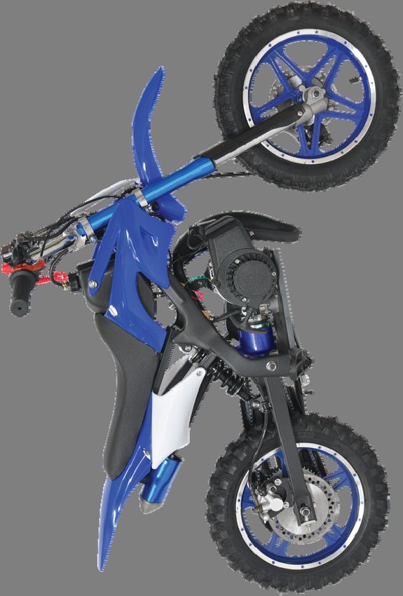
MINI MOTO-X BIKE
Read this Manual thoroughly before riding.
Always wearing protetive clothing while riding.
Imported by
SRGS Pty Ltd
751 Gympie Road
Lawnton, Brisbane, QLD 4501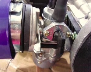
Thanks for purchasing this Mini Moto-X Bike. Please be familiar with and observe all laws and regulations of your State and Local Council. This manual includes important safety information. It covers the main data basic structure and main procedures of operation, adjustment and maintenance. Products are always subject to further improvement, which will cause some difference between the bike and this manual, without further notice.
12 Months Service Warranty
IMPORTANT INFORMATION:
• All warranties will need to be sent back to the supplier for assessment to determine the fault.
• If you have a warranty claim or you require parts, please contact SMG customer service on the below details.
          NO WARRANTY WILL BE PROCESSED WITHOUT THE UNIT BEING ASSESSED
SMG CUSTOMER SERVICE
Australia: 1300 660 457 - New Zealand: 0800 474 876
Operating times: Monday - Friday 8.30am - 5.30pm Australian Eastern Standard Time (AEST)
                                                WARRANTY INFO.:
 PLEASE ENSURE THE INSTRUCTION MANUAL IS READ IN FULL BEFORE STARTING OR OPERATING
What is covered
• Manufacturing fault or defect.
How to claim under this warranty
• Call SMG Customer Service on AUS 1300 660 457 or NZ 0800 474 876
• Ensure you have the following: Original purchase receipt, Model of product, Frame & Engine number of product.
• You will be advised where to take the product to receive your service.
• Provided the issue is a warranty one, repairs will be free of charge. If not you will be advise the cost of repair
before work will commence.
• Take product to authorised service agent for repair.
What is not covered
• Damage caused by incorrectly mixed 2 stroke fuel.                     • Any corrosion or rusting.
• Damage or deterioration due to transport.                             • Damage caused by incorrect assembly
• Damage caused by negligence, misuse, abuse or accident.               • Damage caused by incorrect set up and start up.
• Replacement parts due to general wear and tear. • Products which have been on sold, not original purchaser. • Products with VIN number defacement, modification or removal. • Blockages / damage caused by dust, dirt, spiders webs or • Products which have been serviced by other than an authorised insects. service agent. • Damage caused by the incorrect fitting of accessories. • Products with no original purchase receipt. • Damage caused by overloading, overworking the product. • Damage due to non-servicing of product as is required by the instruction manual WARRANTY This product is guaranteed against defects for a period of 12 months from date of purchase. This warranty is provided by Super Cheap Auto Pty Ltd ACN 085 395 124 (Supercheap Auto) of 751 Gympie Rd Lawnton QLD 4501 Ph (07) 3482 7500. Supercheap Auto will offer a repair, replacement product or store credit if the product is assessed as being defective during the warranty period. To claim under this warranty, take this product to the Front Service Desk of your nearest Supercheap Auto store. For store locations, visit www.supercheapauto.com.au (AUS) or www.supercheapauto.co.nz (NZ). You will need your receipt or proof of purchase. Additional information may be requested of you to process your claim. Should you not be able to provide proof of purchase with a receipt or a bank statement, identification showing your name, address and signature may be required to process your claim. This product may need to be sent to the manufacturer to assess the defect before determining any claim. Faults or defects caused by product modification, misuse and abuse, normal wear and tear or failure to follow user instructions are not covered under this warranty. Our goods come with guarantees that cannot be excluded under the Australian Consumer Law. You are entitled to a replacement or refund for a major failure and for compensation for any other reasonably foreseeable loss or damage. You are also entitled to have the goods repaired or replaced if the goods fail to be of acceptable quality and the failure does not amount to a major failure. Any expenses incurred relating to the return of this product to store will normally have to be paid by you. For more information contact your nearest Supercheap Auto store. The benefits to the consumer given by this warranty are in addition to other rights and remedies of the Australian Consumer Law in relation to the goods and services to which this warranty relatives.
CONTENTS

1. General Safety ……….………………...……………
                                  Page 1        14. Cleaning …………...……………………….……..
                                                                             Page 12
2. Protective Clothing .……….………..………...……
                                       Page 2   15. Storage Guide …………...…..……………….…….
                                                                                 Page 13
3. Accessories ……….………………….………….…..
                              Page 2            16. Maintenance ……………………………………
                                                                            Page 14
4. Identification Number ……………..…………………
                                    Page 3      17. Spark Plug ……………………………..……………….
                                                                             Page 14
5. Handlebar Assembly …………...……………………
                                  Page 4        18. Air Cleaner …………………………...…………………
                                                                              Page 16
6. Handlebar Controls …………...……………………..
                                   Page 5       19. Idle Speed ………………………..……………………..
                                                                             Page 17
7. Fuel & Fuel Tank ……………..……………………..
                                 Page 6         20. Braking System …………………………………………
                                                                              Page 18
8. Tyre ………………….………..………………...………
                           Page 7               21. Checking Brake System ………..……………………….
                                                                                   Page 19
9. Operation Guide ………………….……………………
                                Page 8          22. Inspection of Front Suspension …………………........
                                                                                       Page 19
  9.1 Pre-ride Inspection ……………………..………….
                                     Page 8     23. Transmission System ………………………………………
                                                                                Page 20
  9.2 Starting the Engine ……………...….……………..
                                      Page 8    24. Chain Adjustment ….……...………………………...…..
                                                                                  Page 20
  9.3 Stopping the Engine ……………………………….
                                   Page 10      25. Maintenance Schedule ……………………...……………
                                                                                 Page 21
10. Throttle Operation …..…………………….………..
                                    Page 10     26. Trouble Shooting …………………………………………
                                                                               Page 22
11. Breaking-in ………………………..………..……….
                                Page 11         27. Product Overview …………………………………….
                                                                               Page 23
12. Riding ………………...……..……………………….
                              Page 11           28. Technical Information ……………………………………
                                                                                  Page 24
13. Stopping …………..…………………...……………..
                               Page 12          29. Electrical …………………………………………………
                                                                            Page 25
1. GENERAL SAFETY
WARNING
Safety is the responsibility of the rider. All efforts should be taken to ensure your own safety while riding this bike.
Know these requirements below before you ride.
Obey all Laws and regulations of your State and local council.
SPECIAL ATTENTION:
1. Parents and their children must fully understand everything in this Owner's Manual before riding.
2. This bike is designed for 1 person at a time. Any more than 1 person on this bike at any time is dangerous and will
void the warranty.
3. For OFF-ROAD USE ONLY. This bike is designed to be operated only on level, off-road surfaces, free of obstacles.
4. It is illegal to ride this bike on public roads or highways. If it is necessary to cross a public road, please get off this bike
and push it across.
5. Do not operate this bike under the influence of alcohol or drugs which can impair judgment and result in serious injury
or even death.
6. Keep a safe distance between your bike and other off-road vehicle.
7. Check your bike carefully and make sure all nuts and bolts are tight before riding.
8. Never ride this bike unless it has been properly adjusted and maintained.
9. Do not allow your child to ride without your active supervision.
10.Never run the engine in closed area. The exhaust gas contains poisonous carbon monoxide gas (CO), which can result
in death.
11.Do not touch any part of the engine or exhaust system during or after use. Engine and exhaust components do get very
hot and can cause serious burns if care is not taken.
·1·2. PROTECTIVE CLOTHING
1. Most motorcycle accident fatalities are due to head injures. ALWAYS wear a helmet. You should also wear a face shield
and protective clothing.
2. The engine and exhaust system becomes hot during and after use. Care should be taken during and after use when
inspecting or touching these areas. Protective clothing including, long pants, boots and gloves are recommended.
3. Do not wear loose clothing that could catch on the control levers, footrests or wheels.
3. ACCESSORIES
WARNING
Repairing your bike must be done by an authorised service centre using original parts. Unauthorised servicing
and non original parts may cause the bike to fail or to become unsafe or illegal.
Genuine accessories have been specifically designed and tested on this bike. Don't attempt to change them with any
other accessories manufactured by other companies. If necessary, you are personally responsible for selection,
installation, and use of them. Always follow the guidelines below:
1. Carefully inspect the accessory to make sure that it does not reduce ground clearance, and limit suspension travel,
steering angle or control operation.
2. Accessories may increase the time that hands or feet operate controls, resulting in increased reaction time in emergency.
3. Do not add any electrical equipment that will exceed the bike's electrical system capacity.
4. Do not add any cooling device to the engine.
·2·4. IDENTIFICATION NUMBER
It is recommended that you record your Frame Number and Engine Code in the space provided below.
This can assist in the unfortunate event of the bike being stolen.
① FRAME NUMBER
② ENGINE CODE
FRAME NUMBER: .
ENGINE CODE: .
NOTES
① The Frame Number is stamped on right side of the bike frame head tube.
② The Engine Code is stamped on the top of the engine.
·3·5. HANDLEBAR ASSEMBLY
The Handlebar is detached from the bike for shipping purposes.
Some assembly is required.
Follow below steps to assemble:
1. Take off the top cap of the handlebar clamp by unscrewing the bolts
with Allen key; (see photo)
2. Put the Handlebar on the clamp and put the top cap on, then screw
the bolts in. Handlebar Clamp Bolts
3. Ensure the brake levers face the front of the bike, adjust the handlebar
to a comfortable position then tighten the bolts.
NOTE:
1. Pay attention to the direction of the handlebar and brake hoses
before assembling.
2. Tighten bolts gradually, one at a time. Take care not to over tighten.
·4·6. HANDLEBAR CONTROLS
6.1 Emergency Switch Emergency Cease Fire Device (Red)
The Switch is Red and fixed on the Left side of the Handlebar.
6.2 Emergency Cease Fire Device
This device is fixed on the Left side of the handlebar, for emergency
full stop. Emergency Cease Fire Device should be firmly fitted to the riders
wrist or belt loop by the rope at ALL TIMES.
IMPORTANT - This device is designed to kill the engine in the
event the rider falls off the bike. This device should be firmly fitted Rope (Red) Emergency Switch (Red)
at all times while riding.
The engine will not start if the Emergency Cease Fire
device is not fitted properly.
6.3 Brake Levers:
The LEFT brake lever is for the REAR brake.
The RIGHT brake lever is for the FRONT brake.
Left Brake Lever Right Brake Lever
·5·7. FUEL & FUEL TANK
7.1 Fuel Selection
This engine is a 2-stroke and requires oil to be added to the petrol.
Mix Ratio = 25 : 1. e.g.: 250ml of petrol : 10ml of 2-stroke oil
500ml of petrol : 20 ml of 2-stroke oil
7.2 Fuel Tank
The fuel tank should not be subject to heavy impact, ensure the fuel cap is tightened before riding.
The fuel tank capacity is 1.5L.
WARNING
Gasoline is extremely flammable and is explosive under certain conditions.
Always wear protective equipment when mixing or filling the fuel tank. Breathable Hose
Refuel in a well-ventilated area with the engine stopped. Do not smoke or allow
flames or sparks in the area where gasoline is stored or where the fuel tank
is refueled.
Before refueling, make sure to filter the fuel first.
Be careful not to spill fuel when refueling. Spilled fuel or fuel vapor may ignite.
If any fuel is spilled, make sure the area is dry before starting the engine.
Avoid repeated or prolonged contact with skin or breathing of vapor.
KEEP AWAY OF CHILDREN.
Fuel tank Tank Cap
·6·8. TYRES
1. Proper air pressure will provide maximum stability, riding comfort and tyre life.
2. Check tyre pressure frequently and adjust if necessary.
3. Select the right replacement tyres in accordance with the specifications shown in below table.
Max Pressure 30PSI / 205kPa
Tyre size 2.5-10
NOTE
1. Tyre pressure should be checked before you ride while the tyres are "cold". Check the tyres for cuts, embedded
nails, or other sharp objects.
2. Check the rims for dents or deformation.
3. See a tyre repairer for replacement of damaged or punctured tyres and/or inner tubes.
WARNING
Do not attempt to patch a damaged tyre or inner tube, otherwise wheel balance and tyre reliability may be impaired.
Improper tyre inflation will cause abnormal tread wear and create a safety hazard. The tyre pressure less than the rated
value may result in the tyre slipping on the ground, or coming off from the rim, even the vehicle being out of control.
Operation with excessively worn tyre is hazardous and will adversely affect traction and handling.
When the tread depth in the middle section of tyre reached the limits (9. OPERATION GUIDE
9.1 PRE-RIDE INSPECTION
WARNING
If the Pre-ride check is not performed, severe personal injury or damage to equipment may occur.
Inspect your bike every day before you ride it. The items listed here will only take a few minutes to inspect, and in
the long run they can save time, expenses, and possibly your life.
1. Fuel level - fill fuel tank when necessary - check for leaks.
2. Front and rear brakes - check operation and if adjustment necessary , contact service agent.
3. Tyres - check condition and pressure.
4. Throttle operation - check for smooth opening and full closing in all steering positions; check for throttle grip
free play.
5. Fasteners - check that all nuts, screws and bolts are fixed securely. Steering system - check for its smoothness
and reliability. Correct any discrepancy before you ride. See a professional Mechanic for assitance if you cannot
correct the problem.
9.2 STARTING THE ENGINE
WARNING
Never run the engine in an enclosed area. The exhaust emissions contain poisonous carbon monoxide (CO) gas
which will cause loss of consciousness and lead to death.
·8·Always follow the proper starting procedure described below.
9.2.1 Starting Cold Engine:
1. Fit the Emergency Cease Fire.
2. Turn the fuel tap to ON position.
3. Press choke lever to ON position.
4. Pull the starter rope lightly until you feel resistance, then pull briskly and
return gently. Repeat about 3 times until engine tries to run.
5. After the engine starts, slightly operate the throttle grip to ensure that
the engine reaches the stable idling speed. When engine is running turn choke
to OFF position.
6. Before riding the bike, make sure the engine is warmed up. Choke Lever
9.2.2 Starting Warm Engine:
1. Fit the Emergency Cease Fire.
2. Turn the fuel tap to ON position.
3. Press choke lever to OFF position. Pull the starter rope lightly
until you feel resistance, then pull briskly. Starting may require several times of
pulling the starter rope.
NOTE
Remember to hold the brake lever during the start to avoid sudden
movement of the bike. Left Brake Lever
Slightly opening the throttle may aid starting when cold.
·9·9.3 STOPPING THE ENGINE
Release the throttle grip and press the emergency switch.
CAUTION
Opening or closing the throttle fully or rapidly may make the bike move
suddenly forwards resulting in loss of control.
Throttle Grip Right Brake Lever
10. THROTTLE OPERATION
1. Check for smooth rotation of the throttle grip from the fully open to the
fully closed position at both full steering positions.
2. Measure the throttle grip free play at the throttle grip flange. The standard
free play should be within 2-6 mm.
3. To adjust the free play, loosen the lock nut on the Handle and turn the
adjuster.
Throttle Grip
· 10 ·11. BREAKING-IN
To ensure your bike's future reliability and performance, please pay extra attention during the first twelve (12) hours
riding. During this period, avoid full-throttle riding or loading the engine heavily, be sure to keep changing speed.
NOTE - After the breaking-in period, be sure to conduct maintenance according to the maintenance schedule to keep
the bike in a sound condition, which will extend the service life of the engine.
12. RIDING
WARNING Review "General Safety" before you ride.
1. After the engine has been warmed up, the bike is ready to ride.
2. While sitting on the bike, hold the handlebar steady and kick off the kickstand.
CAUTION - Riding with only one hand may cause the rider to lose control.
3. Open the throttle gradually so the bike moves forward.
4. To slow down the bike, reduce the throttle while braking.
5. Coordinate the throttle with brakes for smooth deceleration.
NOTE - Both the front and rear brakes should be used at the same time and should not be applied strongly
enough to lock the wheel, or braking effectiveness will be reduced and may lead to loss of control.
· 11 ·13. STOPPING
1. Close the throttle while apply the brakes to slow down the bike until it stops.
2. Press the Emergency Switch button on the Left side of handlebar to stop the engine.
3. When not in use turn fuel tap to OFF position.
14. CLEANING
Clean your bike regularly to protect the surface finish and inspect for damage, wear and oil or brake fluid leakage.
CAUTION
High-pressure water or air can damage certain parts of the motorcycle. Avoid spraying high-pressure water at the
following areas: Wheel Hubs, Carburetor, Brake Lever, Air Cleaner, Muffler Outlets, Fuel Tank Bottom, Drive Chain
and Seat Bottom.
1. Wash the bike completely with clean water.
2. Dry the bike, start the engine, and let it run for several minutes.
WARNING
Braking efficiency may be temporarily impaired right after washing the bike. Anticipate longer stopping distance
to avoid a possible accident.
3. Test the brakes before riding the bike. Several applications may be necessary to restore normal braking performance.
Lubuicate the drive chain immediately after washing and drying the bike.
· 12 ·15. STORAGE GUIDE
1. Some measures should be taken when the bike is subjected to a long term storage so as to reduce poor performance.
2. Before storing, perform necessary maintenance to ensure bike performance after-storage.
15.1 STORAGE
1. Clean and dry the bike and wax its surface.
2. Empty the fuel tank and wax its surface.
WARNING
Gasoline is extremely flammable and is explosive under certain conditions. Perform this operation in a well ventilated
area with the storage. Do not smoke or allow or sparks in the area where gasoline is drained or stored and where the
fuel tank is refueled.
3. Remove the spark plug and add 15-20ml engine oil into the cylinder; pull the pull starter to scatter evenly the oil
inside the cylinder, and then reinstall the spark plug.
4. Clean and oil the chain.
5. Lubricate all the cables.
6. Seal the muffler outlet with plastic to protect from moisture.
7. Cover the bike (don't use plastic or other coated materials) and store in cool dry area.
Do not store the bike in direct sunlight.
15.2 REMOVAL FROM STORAGE
1. Take off the cover on the bike and clean it.
2. Clear the inside of the fuel tank, and fill with fresh petrol and oil mixture (25:1).
3. Perform all Pre-ride Inspection Checks. Try the vehicle at low speed in a safe area free from obstacles.
· 13 ·16. MAINTENANCE
CAUTION - Do not dismantle or maintain the bike without mechanical knowledge.
TOOL KIT
Some minor repairs, adjustments and parts replacement can be performed with the tool kit supplied:
① Blade Screw Driver ② Open Wenches
③ Spark plug wrench ④ Allen Keys
17. SPARK PLUG
17.1 Check and Replace
1. Disconnect the spark plug cap from the spark plug.
2. Clean any dirt from around the spark plug base. Remove the spark plug using the plug wrench in the tool kit.
3. Inspect the electrodes and center porcelain for cracks, deposits, erosion or carbon fouling. If the deposits
or erosion is heavy or porcelain is cracked, replace the plug.
Clean a carbon or wet-fouled plug with a plug cleaner, or use a wire brush.
· 14 ·4. Check the spark plug gap using a wire-type feeler gauge. If adjustment is necessary,
bend the side electrode carefully. The spark plug gap should be 0.6-0.8mm.
Make sure the plug washer is in good condition . 0.7±0.1mm
5. With the plug washer attached, thread the spark plug in by hand first to prevent
cross threading, and then tighten with the spark plug wrench.
6. Reinstall the spark plug cap.
①
① Center electrode ② Side electrode
②
NOTE: Replacement Spark Plug – LD BM6A, Torch L6C or NGK BM6A
17.2 IMPORTANT NOTES
1. The Spark Plug must be tightened. When the engine is running, the max pressure in the cylinder can reach up to
100PSI while the mixed gas are igniting. The spark plug's max torque is about 25N.M-30N.M.
ATTENTION - Do not over tighten the spark plug!
2. When assembling the spark plug, ensure the washer is in good condition to aid in sealing the combustion chamber.
3. Check the spark plug cap for cracks and the electrode clearance is correct.
· 15 ·18. AIR CLEANER
The air cleaner should be cleaned every 30 days during normal conditions.
More frequently in dusty or wet conditions.
NOTE - A dirty air cleaner may result in poor engine performance.
CLEANING:
1. Remove air cleaner from carburettor body.
NOTE - Please remove the mudguard first behind the air clearner first.
2. Remove the cap of the clearner.
3. Remove the cover of air cleaner and please mind the direction of core.
4. Shake air cleaner to remove dirt, excessive dust may be removed with low pressure
compressed air from inside the air cleaner.
4. Take care not to get filter wet.
5. Heavily soiled air cleaners may require a brush to remove debris.
CAUTION
It is not recommended to start the engine without the air cleaner fitted, premature wear
of the pistonand cylinder may occur if impurities enter the air intake.
Prevent the air cleaner core from getting wet when washing the bike.
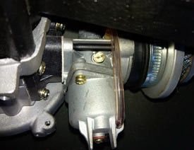
· 16 ·19. IDLE SPEED
The engine must be at normal operating temperature for accurate idle speed
adjustment. Recommended idle speed 2800r/min.
NOTE - Don't attempt to compensate for faults in other systems by adjusting
idle speed. See a prefessional mechanic for regular carburetor adjustments.
1. Warm up the engine.
2. Connect a tachometer to the engine (a remote-controlled one can be used). Idle Speed Adjustment Screw
3. Turn the Adjustment Screw clockwise will increase idle speed and decrease
it by turning counter clockwise.
4. If difficulty is experienced, set the screw to the middle as a starting point.
5. Run the engine again, readjust the Adjustment Screw if necessary.
CAUTION
Since the carburetor is a precise apparatus, do not disassemble without mechanical knowledge.
WARNING
The inlet of carburetor should be often checked to make sure there is no dust or other impurity inside it, otherwise
major engine damage may occur.
· 17 ·20. BRAKING SYSTEM
This bike is equipped with hydraulic disc brake at front and rear. Generally, adjustment is not necessary.
The Left brake lever is for rear brake, and the Right brake lever is for front brake.
Left Brake Lever Right Brake Lever
Rear Disc Brake Front Disc Brake
· 18 ·21. CHECKING BRAKE SYSTEM
The brake system should be checked everyday before you ride the bike.
1. Check the braking function by operating the left and right brake lever seperately and push the vehicle.
2. Check the brake lever for proper free play.
3. Check to see there is no leakage from the system.
4. Check the brake hose and main cylinder for cracks.
5. Check the brake disc for wear.
CAUTION
1. The hydraulic disc brake is designed to operate under high pressure. For the sake of safety and reliability, the service
life of brake hose, main cylinder and brake liquid must not be in good condition.
2. If the lever feels soft or spongy, there is air inside the brake system. In this case, air should be discharged from the
brake system before riding the bike, otherwise, the brake function will drop considerably, and may cause an accident.
Contact a professional mechanic to perform this adjustment.
3. If the hydraulic disc brake system needs to be maintained or repaired, contact a professional mechanic or the
service agent.
22. INSPECTION OF FRONT SUSPENSION
1. Check the front fork assembly by locking the front brake and push the fork up and down vigorously.
Suspension action should be smooth.
2. Check the front shock absorber for oil leaks and deformation.
3. Carefully inspect front suspension fasteners are tight.
· 19 ·CAUTION
Before checking, support the bike firmly to prevent it from falling over.
Should defect be detected on the front fork, replace or repair it.
23. TRANSMISSION SYSTEM
MAINTENANCE
Keep the chain and gears clean, regular periodic maintenance is required.
Inspect the chain is tight or not before riding, adjust it if needed (refer to Chain Adjustment).
If washing the chain in solvents, soak in oil for 30 minutes before using.
It is recommended that the chain is lubricated using a chain lube before and after each ride as well as before storing.
24. CHAIN ADJUSTMENT
Please follow below steps to adjust the drive chain tension:
1. Loosen wheel nuts and then adjust the 2 chain tensioners.
2. Turn the wheel to check it's centered in the swing arm.
3. Make sure the chain is not overtightened.
4. Tighten the wheel nuts.
Chain Tensioner Wheel Nut
· 20 ·25. MAINTENANCE SCHEDULE
The maintenance schedule specifies how often you should have your bike serviced, and what needs attention.
It is essential that your bike is serviced as scheduled for optimum performance and reliability.
The following maintenance schedule specifies all maintenance required under normal conditions to keep your bike in
sound condition. If riding in unusually dusty or wet conditions, bike service should be performed more regularly than
specified in the schedule. Maintenance work should be performed by properly trained and equipped technicians.
I - INSPECT AND CLEAN, ADJUST, LUBRICATE OR REPLACE IF NECESSARY
C - CLEAN; L - LUBRICATE
ITEM INTERVAL 1st 12hours' Ride Every 24hours' ride Yearly
Fuel system I
Operation of throttle I
Air cleaner C
Spark plug I
Idle speed of carburetor I I
Drive chain I&L I&L
Brake disc wear I
Brake system I I
Nuts, bolts and fasteners I I
Wheels I I I
Steering system I
Suspension system I I
· 21 ·26. TROUBLE SHOOTING
Problem Possible Cause Suggested Fix
Emergency cease fire not fitted Fit emergency ceasefire
Fill fuel tank with 2 stroke 25:1 Fuel oil
No Fuel in the tank
ratio mix
Engine will not start Fuel tap in off position Switch fuel tap to on position
Choke is in off position Switch choke to on position
Possible no spark Check /replace spark plug
Clutch seized Return to service Agent for repair
Choke is in the on position Switch Choke to off position
Engine will not run Wont idle Adjust idle speed (ar. 2800r/min)
Air cleaner blocked Clean/replace air cleaner
Fuel Leak under bike Fuel tap left on Switch fuel tap to off position
Chain falls off Chain loose /stretched Adjust chain tension
Check top up fluid level and/or brake
No fluid in reservior
lines for fracture/leaking
Poor Braking
Brake Pads worn Return to service Agent for repair
Oil/Grease on disc Degrease disc and caliper
· 22 ·27. PRODUCT OVERVIEW
Fuel Tank Fuel Tank Cap Throttle Emergency Cease Fire Brake Cylinder
Brake Lever
Muffler
Suspension Fork
Rear Brake Caliper
Front Wheel
Chain Tensioner
Rear Wheel Pull Starter Handle Engine Exhaust Pipe Front Brake Caliper
· 23 ·28. TECHNICLE INFO Engine Type 2-stroke, Single Cylinder, Air Cooled Displacement 49cc Length 1220mm Transmission Chain Width 650mm Compression Ratio 8.0:1 Height 770mm Ignition Mode CDI Wheelbase 845mm Fuel Tank Capacity 1.5L Unit Weight 24.5kg Max Engine Power 1.5kw Steeringbar Angle
29. ELECTRICAL

                 · 25 ·
You can also read