Cummins ISB, ISC, ISL Engine Run Harness Kit - This kit is for 1998 - 2001 EPA/CARB automotive engines.
←
→
Page content transcription
If your browser does not render page correctly, please read the page content below
Cummins
ISB, ISC, ISL Engine
  Run Harness Kit

 This kit is for 1998 - 2001 EPA/CARB
            automotive engines.

              Manufactured by:
              Custom Chassis, Inc.
              Wellington, OH 44090
                 440-647-6401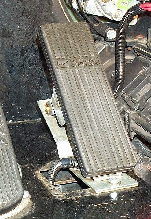
NOTICE:
 Custom Chassis, Inc. (CCI) supplies this kit for
 expressed purpose of Cummins ISB, ISC, and
 ISL engine operation. This installation manual
    provides sufficient information to achieve a
 reliable and successful installation. Therefore,
 CCI is not responsible for damage to engine or
related components due to poor or inappropriate
   installation practices. Care should be taken
while installing this kit to prevent personal injury.
      CCI warranties the quality of this kit for
 workmanship for 30 days from installation date.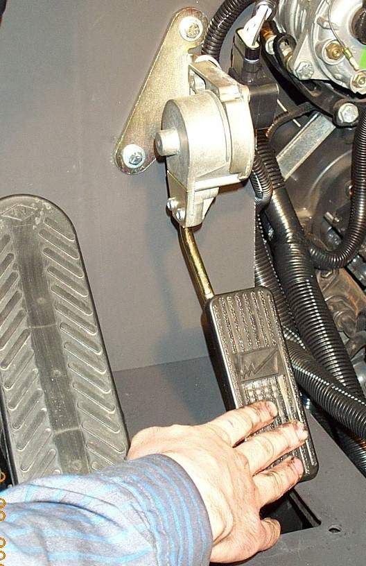
INSTALLATION INSTRUCTIONS
           Thank you for selecting this Cummins engine run harness.
                It will provide you with years of trouble-free use.

Be fore beg inn ing this installatio n, pleas e rea d th oro ug hly th is en tire instru ction boo klet.

Th e ba sic C um m ins run ha rnes s pro vides all the req uired circuits for the en gine to operate
properly. Du e to the flex ibility of the C um m ins EC M, m any m ore fu nction s are available
dep end ing up on the final engine ap plication . Follow ing is a list of additional circuits and /or kits
that CCI can provide.

OPTIONAL CIRCUITS

Cruise Control/ PTO Control - Includes an on/off rocker switch to turn cruise/PTO off or in
stan dby. A m om enta ry on/off/ m om enta ry on rocker sw itch for set/c oas t and resu m e/ac celerate
functions is includ ed. T his sam e sw itch se ts and m aintains en gine spe ed fo r PT O o pera tion.
Brake and clutch switch input is required.

Fan Clutch control - The fan is activated by one of the following: high A/C pressure, high coolant
temp, high intake m anifold temp, increase engine braking demand, or with manual switch
activation . Als o included is an additional roc ke r to m anually ove rride the fa n control.

Transmission Shift Mo dulation Signal - This allows the engine to talk to an Allison electronic,
Allison hydraulic, or Aisin A581 automatic transmission for up shifting and kick down.

Exhaust Brake Control - Includes an on/off rocker switch. This provides transmission clutch,
throttle positio n, and PT O interlock control.

J1587 Data-link Connector - Allows connection to Cum mins computer programm ing and needed
for R oad Relay. A cab-m oun ted conn ecto r is required for au tom otive applica tions a cco rding to
TM C-R P-1202 . This uses the 6 p in diagnostics connec tor.

J1939 Data-link Connector - Allows con nec tion to C um m ins com pute r program m ing an d to
interconnect betwee n other drive train devices. This uses the 9 pin diagnos tics connector.

Tachom eter Signal - Provides a 12 pulses per en gine re volution outp ut s ignal. A com patible
tachometer can also be provided.

Start Lockout - It is used to preve nt the ability to engage the starter w hen the engine is running.
An add itional norm ally closed relay is provided to activate function .

Coolant Level Sensor and Harness - A sensor and short jumper can be provided to allow the
engine to shut down on low coolant. Required for automotive applications.

Complete Instrumentation - Any, or all gauges can be provide d that will com m unicate directly to
the engine.

                                                   Page 1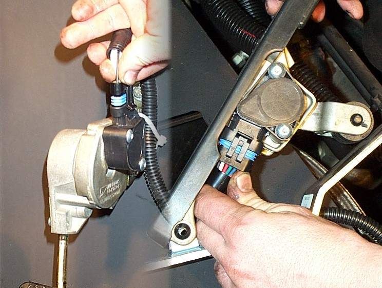
PRE-HARNESS INSTALLATION REQUIREMENTS

•         Before be ginning installation, verify that all parts are included in the kit. Report
          any shortag es or d am aged parts im m ediate ly.

                    BASIC ISB RUN HARNESS KIT PART LIST:
        Qty.           Part Number                                Description
         1                HAR-001              Main harness assem bly
         1                CAB-023              3' batte ry ne gative cable
         1                CAB-034              4' batte ry po sitive cable
         1                CAB-012              2' flat engine gro und cable
         1                CON -001             Throttle pedal assembly - Suspended
         1                CON -004             Switch - Diagnostic, ON/OFF
         1                CON -005             Switch - Diagnostic, Increment/Decrement
         2                CON -007             Brackets - Rocker switch
         1                CON -006             Display - 10 Lamp W arning
         1                CON -003             Ign ition switch assem bly and two ke ys
        20                MIS-001              Cable Ties - 10"

Note:     This harness is designed to be used with a single 12 volt Group 31 battery with
          3/8 " stud term inals. T he battery is N OT included with this kit. Fo r ad ditional cold
          crankin g pow er, a second batte ry m ay be necessary for cold clim ate s. T his
          should be w ired in parallel with the first battery. The add itional battery cables are
          NO T inc luded in this k it.

•         The engine MUST BE securely mounted in vehicle or power unit frame.
•         Fuel lines, air cleaner, radiator, and CAC must be installed and plumbed.
•         Transmission or drive unit must be mounted.
•         DISCONNECT any existin g electrical pow er to th e engine to avoid perm anently
          damaging electrical components.

Note:     Use Caution to avoid personal injury or death.

                                          Page 2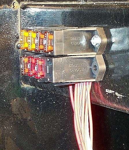
STEP 1 - LAY OUT THE HARNESS ROUTING

•       Route the harness so that it comes close the to object it connects to. Use the
        harness drawing in the Appendix as a guide. The following is the sequence of
        connections on the harness:

        Battery cable lugs
        Start solenoid wire
        Start relay
        Engine power connector
        Engine ECM connector
        W ater in fuel connector
        Grid heater power cabling
        Grid heate r relays
        Throttle pedal connections
        Ignition switch
        W arning lamp panel
        Diagnostic on/off switch & diagnostics increment/decrement switch
        Fuse panel

•       Mount harness with cable ties or rubber coated band style clamps to avoid sharp,
        rotating, or hot objects.

Note:   DO NOT over tighten the cable ties as this can cut insulation and pinch the wires.

Note:   If the harness passes through a firew all or pa nel, use a rub ber grom m et to avoid
        chafing the loom or harness wires.

    STEP 2 - CONNECT THE ROUND POWER CONNECTOR TO ENGINE

•       The round power connector is located at the left rear corner of the engine
        attached with a bracket bolted to the intake m anifold.
•       Grasp the rear body of the connector and rotate it until it aligns with tangs of the
        matting connector. See Figure 1.
•       W ith the rear body aligned, rotate the outer ring at the front to pull the connector
        together. The connector will click when it is fully engaged.

                                      Page 3
Figure 1

    STEP 3 - CONN ECT THE START SOLENO ID WIRE TO THE STARTER:

•       The start solenoid stud is the small stud located at the 12:00 o’clock position on
        the start solenoid. See figure 2.
•       Carefully place the eyelet wire on the stud. Install the original nut and lock
        was her a nd tigh ten using a 8m m nut driver. Sn ug tigh t, but DO NOT over tighten.
•       Be sure that the eyelet does not touch any other surface.

                                     Figure 2

                                      Page 4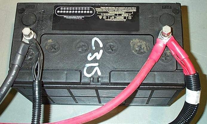
STEP 4 - FRAME OR CHASSIS MOUNT THE HARNESS START RELAY

     •       Fin d a suitab le location for the rela y pro tec ted from exhaust heat, w ate r spray,
             and road grim e.
     •       Bolt or screw the relay to the frame rail or cross mem ber. See Figure 3.

     Note: The relay should be mounted upright to avoid water from running along the wires
           into the connector.

     Note:   Do not mount the relay to the engine as this will reduce the life of the relay. The
             constan t m ovem ent of the engine will cause the contac ts to fail.

                                            Figure 3

STEP 5 - FRAME OR CHASSIS MOUNT THE CUMMINS SUPPLIED VP44 POWER RELAY
                              ( ISB ONLY)

     •       This relay is Cum mins supplied and temporarily banded to the Cum mins harness
             on the left side of the engine near the power connector. This relay must be
             permanently mounted.
     •       Mount the VP44 power relay in the same manner as the start relay. See figure 3.

     Ǹote: The relay should be mounted upright to avoid water from running along the wires
            into the connector.

     Note:   Do not mount the relay to the engine as this will reduce the life of the relay. The
             constan t m ovem ent of the engine will cause the contac ts to fail.

                      S TE P 6 - INS TALL THE E CM CONNECTOR

                                             Page 5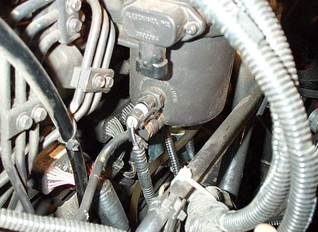
•   The engine ECM is located on the left side middle of the engine under the intake
    manifold. The OEM receptacle is the large rectangular connector located to the
    left of the EC M. Th e conne ctor receptacle m ay be covered by a yellow protective
    cover.
•   Rem ove the protective cover and note the indexing tangs on connector and in the
    receptacle port. See figure 4.
•   Gently insert the connector into the receptacle and carefully tighten the center
    screw using a 4mm Allen wrench. See Figure 5.
•   Carefully tighten the center screw to approximately 25 in-lb.

                                Figure 4

                                Figure 5

                                 Page 6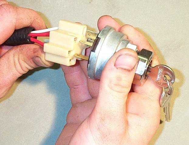
S TE P 7 - A T TA CH W IF (W ATE R IN F ILTER) CONNECTOR

•   The W IF sensor receptacle is located on the forward side of the fuel filter/water
    separator. The fuel filter/water separator is located on the left side of the engine
    with a bracket attached to the intake m anifold. See figure 6.
•   Insert the two-pin connector into the receptacle.
•   The connector will click when fully inserted.

                                 Figure 6

                                  Page 7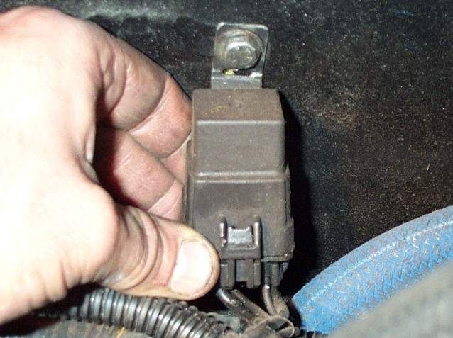
STEP 8 - CONN ECT TH E POW ER CABLES T O TH E INTAKE H EATER T ERMINALS

   •      The two positive intak e heater stu ds are locate d on the re ar of the square grid
          heater section on the inlet section of the intake manifold. See Figure 7.
   •      Attach one cable of the harness to each of the positive studs.
   •      Rem ove the lock washer and nut, then install the cables and re-install the lock
          washer and nut. Tighten to snug. Do not over torque.
   •      Th e op pos ite side of the squ are g rid heater s ection has the two gro und studs.
          There should be a Cumm ins installed jumper cable connecting them together and
          a short cable attached to the engine. See figure 8.

                                       Figure 7

                                      Figure 8

                                       Page 8
STEP 9 - MOUNT INTAKE HEATER GRID RELAYS
• Find a suitable location for the relay panel. It should NOT be mounted on the
eng ine an d aw ay from direct heat.
• The panel should be m ounte d with th e re lays and fu ses in an easily viewable
area. See figure 9.
• The two holes in the panel allow for easy mou nting to the firewall or inner fende r.
• The panel can be mounted with bolts or screws. Check the back of the mounting
surface for obstructions before drilling or screwing.
Figure 9
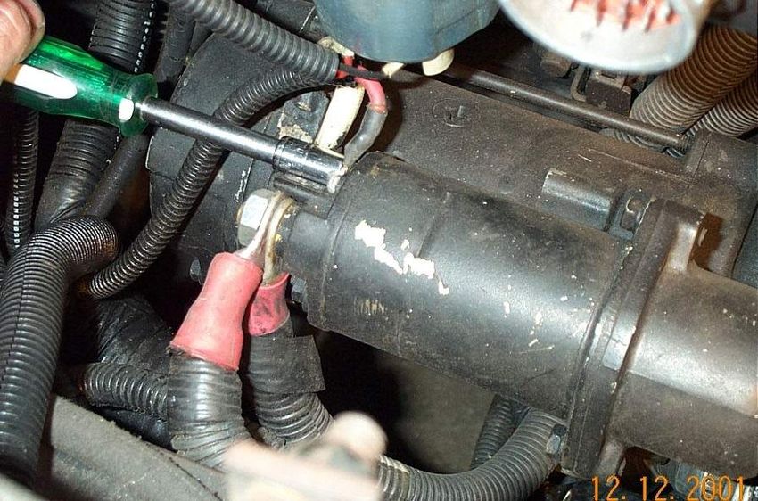
Page 9STEP 10 - MOUNT THE ELECTRONIC THROTTLE PEDAL
• M oun ting the su spen ded p edal (Stan dard).
• To dete rm ine the best p edal position hold the pedal against the firewa ll
while the operator operates the pedal in the seated position. Move the
pedal until the operation is smooth and comfortable. Make sure that the
pedal doesn’t contact the floor or flooring material. See figure 10.
• Use a m arker to locate the two mounting holes.
• Drill the two mounting holes in the firewall after making sure there are no
wires or o the r ob struction s on the opposite side of the firewa ll.
• The pedal m ust be secu rely m ounted to firewall with bolts, flat washers
and lock nuts. DO NOT use screws.
Figure 10
Page 10- OR -
• M oun ting the floo r mo unted peda l (optional).
• To determine the best pedal position, have the operator operate the
pedal in the seated positio n. M ove the pedal until th e operation is
smooth and comfortable. See figure 11.
• Use a m arker to locate the two mounting holes.
• Drill the two mounting in the firewall after making sure there are no wires
or other obstructions on the opposite of the mounting surface.
• The pedal must be securely mounted with bolts, flat washers and lock
nuts . DO NOT use screws.
Figure 11
Page 11STEP 11 - CONNECT SIX PIN CONNECTOR TO THE THROTTLE PEDAL
• Attac hed the six pin conn ecto r in the h arne ss to the m ating c onn ecto r built into
the throttle pedal potentiometer. See Figure 12.
• The connectors will click when fully inserted.
Note: Be careful to ro ute the cables and harness awa y the m oving parts of the pedal to avoid
jam m ing the pedal.
Figure 12
Page 12S TE P 1 2 - IGNITION S W ITCH INS TALLATION
• Find a suitable location for the ignition switch. It should be located at or near
horizontal. This prevents w ater and debris from entering the lock tum bler.
• Th e rec om m end ed m oun ting pa nel thickness is 0.03 0" to 0.090 ".
• The ignition switch mounting hole is 1" in diameter. Hint: Use a 7/8" hole saw.
• Debur and enlarge hole if ne cessary.
• Find and connect the six pin ignition switch connector from the harness to the
back of the ignition switch. See Figure 13.
• Insert the ignition switch in the hole from the back side.
• Install the metal panel nut and tighten to a maximum of 50 in lbs.
Figure 13
Page 13STEP 13 - INSTALL THE WARNING LAMP DISPLAY
• Find a suitable location that can be easily seen by the operator in the operating
position.
• Using figure 14 to create the opening and holes for mounting the warning lamp
display.
• The display can be mounted on top of the panel or below for a recessed look.
• No. 10 machine screws (not included) work best for mounting the panel. Do not
over tighten the screws as this will pucke r the plastic panel.
• Find and connect the male and female 12 pin lamp connectors from the harness
to the app ropriate co nne ctors on the lam p disp lay pigtail.
Figure 14
Note: This run harness only uses the five lower indicator lamps. The left turn, oil pressure,
volts, coolant temp, and right turn lamps are available for customer use. The harness has
a 12" lead in pins 6 thru 10 in each the harness connectors for customer connection. The
male connector is for power and the female connector is for ground.
DISPLAY PIN LOCATIONS
#6 Left Turn
#7 Oil Pressure
#8 Volts
#9 Coolant tem perature
# 10 Right turn
Page 14STEP 14 - MOUN T DIAGNOSTIC SW ITCHES
• Find a suitable loc ation that is ac ces sible by the op erato r, but is n ot pro ne to
accidental activation.
• Th e rec om m end ed p ane l moun ting thick nes s is 0.0 9" to 0.19".
• Create a hole that is 2.02" long by 1.90" high.
• Assem ble the rocker switches in the rocker switch bezel. The on/off switch
should be located on the left and the mom entary on/off/mom entary on switch on
the left.
• Find the two six pin connectors in the harness for the diagnostic switches. Feed
the connectors th rough the diagnostic switch hole just c reate d. T his will aid in
connecting the switch es pro perly.
• The connector with two wires is installed on the on/off rocker switch. The
con nec tor with three wires is installed on the m om enta ry rock er sw itch. Pu sh to
seat the connectors over the spade terminals. See figure 15.
• W ith the connectors installed, push the rocker switch assembly in the mounting
hole. The as sem bly should sn ap into place .
Figure 15
Page 15STEP 15 - MOUNT THE FUSE BLOCKS
• The two fus e blocks can be m ounte d togethe r (recom m ended) or s eparate ly.
• The fuse blocks should not be mounted upside down increasing the chance of
fuses loosening from vibration.
• The fuse blocks should me mounted in an easily accessible, weatherproof
location. See Figure 16.
Figure 16
Page 16STEP 16 - CONN ECT BATTERY CA BLES
Engine Ground
• Connect the flat braided engine grounding cable to an available threaded hole on
the upper engine block just above the flywheel housing and to frame m ounting
bolt or stud.
• Tighten both m oun ting nu ts se curely to insure prope r con tact.
• Apply dielectric grease , anti-se ize, or sim ilar prod ucts to both m oun ting po ints to
reduce the chances of corrosion.
Battery Ground
• Connect the shorter (negative) battery cable first to one of the starter mounting
bolts and then to the negative battery terminal. See figure 17.
• Tighten the starter b olt sec urely to ins ure p rope r con tact.
• Also install the two ground (black heat shrink) harne ss term inals on the negative
battery term inal.
• Apply dielectric grease , anti-se ize, or sim ilar prod ucts to both m oun ting po ints to
reduce the chances of corrosion.
Battery Power
• Connect the longer (positive) battery cable first to large starter solenoid stud and
to the positive battery terminal. See figure 18.
• Tighten the starter b olt sec urely to ins ure p rope r con tact.
• Also install the three power (red he at shrink) harness terminals on the po sitive
battery term inal.
• Apply dielectric grease , anti-se ize, or sim ilar prod ucts to both m oun ting po ints to
reduce the chances of corrosion.
Figure 17
Page 17Figure 18
STEP 17 - FINAL CHECKS AND SYSTEM TESTS
• Us ing ca ble ties and /or ha rnes s clam ps tie u p an y lose or han ging wires .
• Check all routing to prevent chafing or pinching the harness.
• Ch eck that all wiring avoids an y moving parts .
• Check all mounting fasteners to ensure properly tightened.
• Turn the ignition switch to the on position and observe the followings functions.
• The EC M powe rs the fue l pum p and a whirring sound will continu e until
the fu el pressu re is m et.
• W ith the diagnostic switch in the off position, the indicator lamps
(warning, stop, service engine, wait to start, and water in fuel) light up for
two secon ds and g o off in the given order, one after the other, to verify
they are wo rking an d wired co rrectly.
• If the ECM determ ines the cold starting aid is neede d, the wait to start
lam p will rem ain on until the inta ke hea ters h ave timed o ut.
• If an active fault is present, one of the three warning lamps will remain on
determined by the type of fault being sensed. See the diagnostics
section in the appendix for further explanation.
• If no faults are noted, turn the ignition to the start position to begin engine
cranking. If the engine does not start after 30 seconds , wait 1 minute for the start
to c ool down . Repeat as necessary.
• The engine electronic subsystems and the starter motor are independent
of each othe r. During the cranking ph ase, with the key switch in the start
position, the ECM commands all the fuel needed to start the engine. THE
THROTTLE PEDAL HAS NO EFFECT W HILE CRANKING THE
ENGINE.
• W hile the engine is crankin g, th e ECM is perform ing additional diagnostic
and status operations. An active fault may cause one of the indicator
lamps to illuminate and remain lighted; which lamp is illuminated,
dep end s on the severity of the fa ult.
Page 18APPENDIX
Table of Contents:
Section A - Wiring Schematic . . . . . . . . . . . . . A-1
Section B - Harness Connector Diagram . . . . . A-2
Section C - Diagnostics . . . . . . . . . . . . . . . . . . A-3
Section D - Fault Code Information . . . . . . . . . A-4WIRING SCHEMATIC
Page A-1Page A-2
DIAGNOSTICS
The ISB, ISC, and ISL engines have a built-in diagnostic capability which alerts the
operator of a system problem while the engine is running by illuminating one of the
indicator lam ps. The w arning (yellow) lam p, when lighted warns the op erator of an active
component or system fault. W hile it denotes a failure has happened, the vehicle can be
operated. The vehicle should be serviced to solve the problem, but the situation is not
considered an emergency. The lighted stop (red) lamp indicates a major ISB, ISC, ISL
engine problem and the vehicle should be stopped as soon as possible.

Note: The red lamp will be flashed in scenarios where engine protection shutdown
is about to shut the engine down.

The engine protection system uses an indicator lamp to alert the operator of a coolant
tem perature high, intake m anifold tempe rature high, oil pressure low, or coo lant (water)
level low condition. The lamp will turn on at the occurrence and then begin blinking after
a period of time. This blinking operation is to warn the operator that something has been
active for a period of time or else the pressure or temperature condition has become
worse and engine shutdown is about to occur, if the shutdown feature has been enabled.

Note: The engine protection faults defined above w ill turn on the yellow and red
lamps depending on the severity of the fault detected with the exception of the
coolant level engine protection which will turn on the service engine lamp.

In addition to alerting the operato r of system fau lts, the lam ps are used in the diagnostic
operation. The diagnostic mode begins when the ignition switch and diagnostic test
switch are on and the engine is not running. The yellow lamp flashes at the beginning of
a fault code sequence, the red lamp flashes the three digit code for the active fault and
yellow lam p ag ain flas hes to separa te the previous red lam p se que nce from the next one.
The second diagnostic switch allows the operator to toggle upward or downward through
the fault codes. At the conclusion of the diagnostic mode, the diagnostic test switch
should be turned off.

                                          Page A-3
FAULT CODE INFORMATION for ISB, ISC, ISL ENGINES
Flash
Code/ REASON EFFECT (Only when fault code is active) APPLICATION
Lamp
111*
ECM internal hardware error. Possible no effect or engine may run rough or not start. ISB, ISC, ISL
W arning
115* No engine speed or position signal detected at pin No. 17 of the Engine power derates.
ISB, ISC, ISL
W arning engine harness. Possible white smoke.
121* No engine speed or position signal detected at pin No. 9 of the No engine speed and position backup for main speed/position
ISC, ISL
W arning engine harness. sensor.
122 High voltage detected at the boost pressure sensor signal pin No.
Engine will derate to no-boost fueling. ISB, ISC, ISL
W arning 45 of the engine harness.
123 Low voltage detected at boost pressure sensor signal pin No. 45
Engine will derate to no-boost fueling. ISB, ISC, ISL
W arning of the engine harness.
Engine idles when idle validation switch indicates idle and ramps up
131 High voltage detected at throttle position signal pin No. 30 of the
to a default set speed when the idle validation switch indicates off ISB, ISC, ISL
W arning OEM harness.
idle.
132 Low voltage detected at throttle position signal pin No. 30 of the Engine idles when idle validation switch indicates idle and ramps up
ISB, ISC, ISL
W arning OEM harness. to a default set speed when idle validation switch indicates off-idle.
135 High voltage detected at oil pressure signal pin No. 33 of the Default value used for oil pressure.
ISB, ISC, ISL
W arning engine harness. No engine protection for oil pressure.
141 Low voltage detected at oil pressure signal pin No. 33 of the Default value used for oil pressure. No engine protection for oil
ISB, ISC, ISL
W arning engine harness pressure.
143 Oil pressure signal indicates oil pressure below the low engine Power and/or speed derate and possible engine shutdown if engine
ISB, ISC, ISL
W arning protection limit. protection shutdown feature is enabled.
144 High voltage detected at coolant temperature signal pin No. 23 of Default value used for coolant temperature. No engine protection for
ISB, ISC, ISL
W arning the engine harness. coolant temperature.
145 Low voltage detected at coolant temperature signal pin No. 23 of Default value used for coolant temperature. No engine protection for
ISB, ISC, ISL
W arning the engine harness. coolant temperature.
146 Coolant temperature signal indicates coolant temperature has Power derate and possible engine shutdown if engine protection
ISB, ISC, ISL
W arning exceeded the minimum engine protection lim it. shutdown feature is enabled.
151 Coolant temperature signal indicates coolant temperature has Power and/or speed derate and possible engine shutdown if engine
ISB, ISC, ISL
Stop exceeded the engine protection lim it. protection shutdown feature is enabled.
Page A-4FAULT CODE INFORMATION for ISB, ISC, ISL ENGINES
153 High voltage detected at intake manifold temperature signal pin Default value used for intake manifold temperature. No engine
ISB, ISC, ISL
W arning No. 34 of the engine harness. protection for intake manifold temperature.
Flash
Code/ REASON EFFECT (Only when fault code is active) APPLICATION
Lamp
154 Low voltage detected at intake manifold temperature signal pin No. Default value used for intake manifold temperature. No engine
ISB, ISC, ISL
Warning 34 of the engine harness. protection for intake manifold temperature.
155 Intake manifold air temperature signal indicates intake manifold air Power and/or speed derate and possible engine shutdown if engine
ISB, ISC, ISL
Stop temperature is above the engine protection limit. protection shutdown feature is enabled.
A/C Clutch driver signal indicates a short to ground when
191 Can not turn on A/C ISB, ISC, ISL
commanded on.
221 High voltage detected at ambient air pressure signal pin No. 32 of
Engine power derate. ISC, ISL
Warning the engine harness.
222 Low voltage detected at ambient air pressure signal pin No. 32 of
Engine power derate. ISC, ISL
Warning the engine harness.
234 Engine speed signal indicates engine speed has exceeded the Fuel to injectors disabled until engine speed falls below the overspeed
ISB, ISC, ISL
Stop overspeed limit. limit.
235
Coolant level signal at pin No. 37 of the engine harness indicates Power and/or speed derate and possible engine shutdown if engine
Service ISB, ISC, ISL
coolant level is low. protection shutdown feature is enabled.
Engine
Engine speed limited to “Max. Engine Speed without VSS”. Cruise
241 Vehicle speed signal on pin Nos. 8 and 18 of the OEM harness has
control, gear-down protection and the read speed governor will not work. ISB, ISC, ISL
Warning been lost.
Trip information data that is based on mileage will be incorrect.
Invalid or inappropriate vehicle speed signal indicated on pin Nos. 8 Engine speed limited to “Max. Engine Speed without VSS”. Cruise
242
and 18 of the OEM harness indicating on intermittent connection or control, gear-down protection and road speed governor will not work. ISB, ISC, ISL
Warning
possible tampering. Trip information data that is based on mileage will be incorrect.
Error detected in exhaust brake relay enable circuit at pin No. 42 of
243 Exhaust brake will not work. ISB, ISC, ISL
the engine harness.
Error detected in fan clutch relay enable circuit at pin No. 31 (ISB) Electronic control module (ECM) cannot control the engine cooling fan.
245 ISB, ISC, ISL
and pin No. 41 (ISC) of the engine harness. Fan will remain on or off.
261* VP44 Fuel Pump Control Module indicates the fuel temperature has
Power derate. ISB
Warning exceeded the engine protection limit.
High voltage detected at fuel temperature signal pin No. 35 of the
263 Default value used for fuel temperature. Possible low power. ISC, ISL
engine harness.
Page A-5FAULT CODE INFORMATION for ISB, ISC, ISL ENGINES
264 High or low voltage detected at the fuel temperature sensor signal Default value used for fuel temperature. Possible low power and no
ISB
Warning circuit inside the VP44 pump controller. engine protection for fuel temperature.
Low voltage detected at fuel temperature signal pin No. 35 of the
265 Default value used for fuel temperature. Possible low power. ISC, ISL
engine harness.
Flash
Code/ REASON EFFECT (Only when fault code is active) APPLICATION
Lamp
268* Fuel pressure in the accumulator is not changing with engine
Power derate. Engine may run rough. ISC, ISL
Warning operating conditions.
271 Low or no current detected on front pumping control valve return pin
Low power. Poor Performance ISC, ISL
Yellow No.21. (Set only during control valve click test)
272 High current detected on front pumping control valve return pin No.
Low power. Poor performance. Possible damage to the ECM. ISC, ISL
Warning 21.
273 Low or no current detected on rear pumping control valve return pin
Low power. Poor performance. ISC, ISL
Warning No. 15. (Set only during control valve click test)
274 High Current detected on rear pumping control valve return pin No.
Low power. Poor performance. Possible damage to the ECM. ISC, ISL
Warning 15.
275
Engine ECM has detected a failure in the front pumping element. Low power. Poor performance. ISC, ISL
Warning
276 Injection Control Valve is shut down and engine will not run. Possible
High current detected on injection control valve return pin No. 7. ISC, ISL
Warning ECM damage.
277*
Engine ECM has detected a failure in the injection control valve. Low power. Engine may not run. ISC, ISL
Warning
278*
Error detected in lift pump circuit at pin 11 of the engine harness. Possible low power. Engine may die, run rough or be difficult to start. ISB, ISC, ISL
Warning
279 Low or no current detected on injection control valve return pin No.
Low power. Engine may not run. ISC, ISL
Warning 7. (Set only during control valve click test)
281
Engine ECM has detected a failure in the front pumping element. Possible no effect or engine power derate. ISC, ISL
Warning
282
Engine ECM has detected a failure in the rear pumping element. Possible no effect or engine power derate. ISC, ISL
Warning
283 High voltage detected at main engine speed/position sensor voltage ECM will use the VP44 pump speed (ISB) or the engine position signal
ISB, ISC, ISL
Warning supply pin 8 of the engine harness. (ISC,ISL) as a backup. Possible white smoke and power loss.
Page A-6FAULT CODE INFORMATION for ISB, ISC, ISL ENGINES
284 Low voltage detected at main engine speed/position sensor voltage ECM will use the VP44 pump speed (ISB) or the engine position signal
ISB, ISC, ISL
Warning supply pin 8 of the engine harness. (ISC,ISL) as a backup. Possible white smoke and power loss.
285 The software has detected an error due to a parameter time-out on
At least one mux device will not work properly. Engine may idle only. ISB, ISC, ISL
Warning the multiplexed data bus.
286 The software indicates that the multiplexed data bus is not
Engine will idle only. ISB, ISC, ISL
Warning erroneous but is invalid.
Flash
Code/ REASON EFFECT (Only when fault code is active) APPLICATION
Lamp
287 The software indicates that the multiplexed data is not valid and
Engine will idle only. ISB, ISC, ISL
Warning erroneous for the accelerator pedal sensor.
288 The software indicates that the multiplexed data is not valid and
Engine will not respond to remote throttle. ISB, ISC, ISL
Warning erroneous for the remote throttle.
319
Power to the real time clock has been interrupted and its setting is
Service Time stamp in ECM power down data will be incorrect. ISB, ISC, ISL
no longer valid.
Engine
328
Engine ECM has detected a failure in the rear pumping element. Low power. Engine may not run. ISB, ISC, ISL
Warning
329* Engine ECM has detected an over pumping failure in the CAPS Instability at idle accompanied by low power or extremely poor
ISC, ISL
Stop pump. performance and severe black smoke. Engine may shutdown.
Default value used for sensors connected to this +5 volt supply. Engine
352 Low voltage detected at engine position sensor +5 volt supply, pin
will derate to no-boost fueling and loss of engine protection for oil ISB, ISC, ISL
Warning No. 10 of the engine harness.
pressure. Intake manifold pressure and coolant temperature.
361
Continuous power detected at VP44 fuel control valve. Fueling to injectors disabled. Engine dies. ISB
Stop
362
Low voltage or no voltage detected at the VP44 fuel control valve. Engine will lose power and may shut down. ISB
Warning
363 No fuel control valve movement detected by the VP44 pump
Engine power loss. ISB
Warning controller.
No communications or invalid data transfer rate detected on date
364*
link between ECM and VP44 pump controller at pins 4 and 13 of the Engine will run at a backup mode set speed when throttle is off idle. ISB
Warning
engine harness.
365 Low voltage detected at VP44 pump controller supply voltage
Engine may lose power and may shut down. ISB
Warning circuit.
Page A-7FAULT CODE INFORMATION for ISB, ISC, ISL ENGINES
366 VP44 pump controller battery voltage measurement is outside the
Engine will lose power and may shut down. ISB
Warning range between 6 and 24 volts.
367
VP44 pump speed/position sensor signal lost. Fueling to injectors is disabled and engine will shutdown. ISB
Stop
368 The VP44 pump can not achieve the timing value being
Significant engine power loss. ISB
Warning commanded by the ECM.
369 VP44 pump controller does not detect engine position pulse at pin
Significant engine power loss. Possible white smoke. ISB
Warning No. 7 of the engine harness.
Flash
Code/ REASON EFFECT (Only when fault code is active) APPLICATION
Lamp
VP44 pump controller detects continuous voltage at idle select pin
If communication is lost between the ECM and VP44 pump controller,
372* No. 16 of the engine harness...OR...pump controller detects an
engine will either only idle or will be stuck at a slightly higher set speed, ISB
Warning open circuit or short circuit to ground at idle select pin 16 of the
regardless of throttle position.
engine harness.
373 High voltage detected at VP44 fuel shut off signal pin No. 6 of the
Fueling to injectors disabled. Engine will shut down. ISB
Stop engine harness.
374*
VP44 pump controller has detected an internal error. Engine power derate or engine may die. ISB
Warning
376*
No calibration in the VP44 pump controller. Fueling to injectors disabled. Engine will shut down. ISB
Stop
377 VP44 pump controller is not powering down when key switch power
Equipment batteries may be drained low during long shutdown periods. ISB
Warning is removed from the engine control module.
381* Error detected in cold start aid relay 1 enable circuit at pin No. 41 of Intake air heater can not be fully energized by the ECM. Possible white
ISB, ISC, ISL
Warning the OEM harness. smoke and/or hard starting.
382* Error detected in cold start aid relay 2 enable circuit at pin No. 31 of Intake air heater can not be fully energized by the ECM. Possible white
ISB, ISC, ISL
Warning the OEM harness. smoke and/or hard starting.
385 High voltage detected at OEM harness sensor supply pin No. 10 of
Sensors connected to this +5 volts supply will not function. ISB, ISC, ISL
Warning the OEM harness.
Default value used for sensors connected to this +5 volts supply.
386 High voltage detected at the engine harness sensor +5 VDC supply
Engine will derate to no-boost fueling and loss of engine protection for oil ISB, ISC, ISL
Warning pin No. 10 of the engine harness.
pressure, intake manifold temperature, and coolant temperature.
387 High voltage detected at the throttle position sensor +5 VDC supply Engine idles when idle validation switch indicates idle and ramps up to a
ISB, ISC, ISL
Warning pin No. 29 of the OEM harness. default set speed when idle validation switch indicates off-idle.
Page A-8FAULT CODE INFORMATION for ISB, ISC, ISL ENGINES
391 Error detected in VP44 power supply relay enable circuit at pin No.
Possible no effect on performance or engine may die. ISB
Warning 43 of the engine harness.
415 Oil pressure signal indicates oil pressure below the very low engine Power and/or speed derate and possible engine shutdown if engine
ISB, ISC, ISL
Stop protection limit. protection shutdown feature is enabled.
418 Water-in-fuel signal indicates the water in the fuel filter needs to be
Excessive water in the fuel can lead to severe fuel system damage. ISB, ISC, ISL
WIF drained.
Voltage detected simultaneously on both the coolant level high and
422 low signal pins No. 27 and 37 of the engine harness ...OR... no
No engine protection for coolant level. ISB, ISC, ISL
Warning voltage detected on either pin. (Fault is active for Switch type
coolant level sensors only)
Flash
Code/ REASON EFFECT (Only when fault code is active) APPLICATION
Lamp
429 Low voltage detected at water-in-fuel signal pin 40 of the OEM
No water-in-fuel protection. ISB, ISC, ISL
Warning harness.
431 Idle validation signals on pins No. 25 and 26 of the OEM harness
No effect on performance, but loss of idle validation. ISB, ISC, ISL
Warning indicate no voltage detected simultaneously.
Idle validation signal at pin No. 26 of the OEM harness indicates
the throttle is at the idle position when the throttle position signal at
pin No. 30 of the OEM harness indicates the throttle is not at the
432
idle position...OR...idle validation signal at pin No. 26 of the OEM Engine will only idle. ISB, ISC, ISL
Warning
harness indicates the throttle is not at the idle position when the
throttle position signal at pin No. 30 of the OEM harness indicates
the throttle is at the idle position.
Boost pressure signal indicates boost pressure is high when other
433
engine parameters (i.e. speed and load) indicate boost pressure Possible over fueling during acceleration. Increase in black smoke. ISB, ISC, ISL
Yellow
should be low.
Supply voltage to the ECM fell below 6.0 volts for a fraction or a Possible no noticeable performance effects ...OR... engine dying or hard
434*
second ...OR... the ECM was not allowed to power down correctly starting. Fault information, trip information, maintenance monitor data, ISB, ISC, ISL
Warning
(retain battery voltage for 30 seconds after key start) trending data, and user activated data logger data may bee inaccurate.
Voltage detected at ECM power supply pins No. 38, 39, and 40 of
441
the engine harness indicates the ECM supply voltage fell below 6 Engine will die or run rough. ISB, ISC, ISL
Warning
volts.
Voltage detected at ECM power supply pins 38, 39, and 40 (and pin
442
No. 50 for ISC, ISL) of the engine harness indicates the ECM None on performance. ISB, ISC, ISL
Warning
supply voltage is above the maximum system voltage level.
Page A-9FAULT CODE INFORMATION for ISB, ISC, ISL ENGINES
443 Low voltage detected at throttle position sensor +5 volts supply pin Engine idles when idle validation switch indicates idle and ramps up to a
ISB, ISC, ISL
Warning No. 29 of the OEM harness. default set speed when idle validation switch indicates off-idle
444 Low voltage detected at OEM harness sensor +5 volts supply pin Sensors connected to this +5 volts supply (i.e. remote throttle position
ISB, ISC, ISL
Warning No. 10 of the OEM harness. sensor) will not function.
449 Fuel pressure signal indicates that fuel pressure has exceeded the Fuel pumping is stopped until pressure returns to normal. Possible fuel
ISC, ISL
Warning maximum limit for the given engine rating. pump damage may result.
451 High voltage detected at fuel pressure sensor signal pin No. 46 of
Low power, reduced performance. ISC, ISL
Warning the engine harness.
452 Low voltage detected at fuel pressure sensor signal pin No. 46 of
Low power, reduced performance. ISC, ISL
Warning the engine harness.
Flash
Code/ REASON EFFECT (Only when fault code is active) APPLICATION
Lamp
488 Intake manifold temperature signal indicates intake manifold Power derate and possible engine shutdown if engine protection
ISB, ISC, ISL
Warning temperature is above the minimum engine protection threshold. shutdown feature is enabled.
493 ECM has detected a circuit failure on the Injection Control Valve
Small power loss. ISC, ISL
Warning Identifier circuit.
515 High voltage detected at the auxiliary +5 sensor supply voltage pin
No engine protection for coolant level. ISB, ISC, ISL
Warning No. 49 of the engine harness.
516 Low voltage detected at the auxiliary +5 volts sensor supply voltage
No engine protection for coolant level. ISB, ISC, ISL
Warning pin 49 of the engine harness.
517 A mechanically stuck fuel control valve has been detected by the
Engine may shutdown. ISB
Warning VP44 fuel pump controller.
529* Error detected in the Dual Output B circuit pin No. 1 of the engine The device being controlled by the Dual Output Driver B signal will not
ISB, ISC, ISL
Warning harness (ISC) or pin No. 21 of the engine harness (ISB). function properly.
539 Open circuit failure of the Injection Control Valve transorb pin No. 6
Low power, possible ECM damage. ISC, ISL
Warning of the engine harness.
551 Idle validation signals on pins No. 25 and 26 of the OEM harness
Engine will only idle. ISB, ISC, ISL
Warning indicate voltage detected simultaneously on both pins.
591 High voltage detected at the exhaust pressure sensor signal pin No. Default value used for exhaust pressure. Engine will be limited to no-
ISL
Warning 43 of the engine harness. boost fueling.
592 Low voltage detected at the exhaust pressure sensor signal pin No. Default value used for exhaust pressure. Engine will be limited to no-
ISL
Warning 43 of the engine harness. boost fueling.
Page A-10FAULT CODE INFORMATION for ISB, ISC, ISL ENGINES
593 VGT speed signal on pin No. 4 of the engine harness indicates the
Reduce turbo charger speed. No fueling derate. ISL
Warning VGT has exceeded the maximum limit.
594 VGT speed signal on pin No. 4 of the engine harness indicates the
No effect. ISL
Warning VGT speed is below the minimum limit.
The duel output feature is a customer specialized calibration and it
599 has initiated an engine shutdown based on the customer’s specified
Engine will shutdown ISB, ISC, ISL
Stop operating conditions, engine sensor value, and/or OEM inputs to the
ECM
768 Error detected in the Output Device Driver (VGT or Transmission
Cannot control the VGT or Transmission, depending on application. ISB, ISC, ISL
Warning Shift Modulation Signal) signal pin No. 21 on the OEM harness.
779
Low or no voltage detected at the OEM switch. Engine will lose power and may shut down. ISB, ISC, ISL
Warning
Note: * Indicates multiple errors can generate this fault code.
Page A-11Document # 032902
Custom Chassis, Inc.
21950 G ore O rphan age Road
Wellington, OH 44090
Phone 440-647-6401
Fax 440-647-3817You can also read