COSI7: THE NEW CEA REFERENCE ELECTRO-NUCLEAR SIMULATION TOOL
←
→
Page content transcription
If your browser does not render page correctly, please read the page content below
EPJ Web of Conferences 247, 13001 (2021)                                                               https://doi.org/10.1051/epjconf/202124713001
PHYSOR2020

                                         COSI7: THE NEW CEA REFERENCE

                                   ELECTRO-NUCLEAR SIMULATION TOOL

                                                              G. KRIVTCHIK1
                      1
                          CEA, DES, IRESNE, DER, SPRC, F-13108 Saint-Paul-lez-Durance, France.

                                                        guillaume.krivtchik@cea.fr

                                                                   ABSTRACT

                 Nuclear fuel cycle scenario studies are used as a prospective analysis tool in order to provide
                 stakeholders with decision aid. Nuclear fuel cycle simulation tools model the deployment of
                 reactor fleets, the mass flows in the fuel cycle, and track the nuclear materials. The CEA has
                 been developing for more than 30 years the nuclear fuel cycle tool COSI. The latest version,
                 COSI7, was designed in order to model dynamic systems of ever-increasing complexity with
                 improved user experience. The new developments include functionalities designed to
                 improve the user experience as well as new physical models and post-processing capabilities.
                 COSI7 supersedes COSI6 as the CEA reference nuclear fuel cycle simulation code starting
                 January 2020.

         KEYWORDS: COSI, fuel cycle simulation tool, scenario

                                                            1. INTRODUCTION

         Nuclear fuel cycle scenario studies are used as a prospective analysis tool in order to provide stakeholders
         with decision aid. They aim to help decision-makers understand the impact of decisions in complex
         systems. A way to provide such help consists in modeling the whole nuclear fuel cycle system as a
         physical system. Nuclear fuel cycle scenario codes tackle such problems, and use modeling techniques to
         track inventories, mass flows, and interactions between the different facilities of the fuel cycle. For more
         than 30 years, the CEA Cadarache has been developing COSI, the CEA nuclear fuel cycle simulation
         (FCS) tool. The previous iteration of the software, COSI6 [1], written in Java and using the Discrete
         Event Simulation (DES), was released in 2006, and aimed to improve the simulation algorithms
         robustness and upgradability. Several intermediate versions of COSI6 were also generated, mostly in
         order to reduce the computing resources required by scenario simulation. For instance, COSI6 versions
         featuring parallel computing or surrogate models for depletion computations were released [2,3].
         However, as COSI6 performance improved, scenarios simulations featured an increased level of
         operational detail and required always more fine-tuning of facilities and strategies, progressively shifting
         the time-consuming processes of making scenarios from simulation towards dataset generation and
         scenario results analysis. COSI7 is a complete re-write in C++ of COSI6, designed in order to tackle the
         new challenges induced by the ever-increasing complexity of the scenarios. COSI7 features many new
         functionalities aimed at refining the modeling capabilities while simplifying the dataset generation and
         scenario analysis tasks. While the general behavior of physical models and the DES formalism were
         preserved, the architecture of the code was fully re-designed to improve performance and maintainability.

  © The Authors, published by EDP Sciences. This is an open access article distributed under the terms of the Creative Commons Attribution License 4.0
  (http://creativecommons.org/licenses/by/4.0/).
EPJ Web of Conferences 247, 13001 (2021) https://doi.org/10.1051/epjconf/202124713001
PHYSOR2020
The new features of COSI7 can be broadly separated into two categories: improving the user experience
and refining the physical models. Such features are presented hereafter.
2. NEW FUNCTIONALITIES TO IMPROVE USER EXPERIENCE
This section discusses the new COSI7 functionalities that were implemented to improve the user
experience, during the intricately linked processes of dataset generation, scenario simulation and scenario
results analysis. Most of these functionalities are related to the two COSI7 graphical user interfaces
(GUI).
2.1. Improved Expert GUI
Decades-long experience of scenario-making at CEA Cadarache shows that a substantial proportion of the
scenario-making process is spent generating datasets. Efforts were made to improve the COSI expert GUI
in order to make the dataset more understandable, more flexible and to limit possibilities for input errors.
Like the COSI6 GUI, the COSI7 expert GUI uses the bottom-up formalism: low-level objects, such as
fuel types, are included in consecutive higher-level objects, such as batch types, reactor types, reactors
and so on. In order to ease dataset browsing in COSI7, each higher-level object possesses hyperlinks
directing to the associated lower-level objects. As in COSI6, all of the objects are accessible via a tree.
Given the high number of objects included in a COSI7 dataset (usually several hundred objects), a dataset
search engine was also included in the GUI. The user types a query in the always open search field and
the GUI display the corresponding objects.
A log browser, containing all the dataset modifications sequence, was implemented, along with “Undo”
and “Redo” buttons allowing the user to undo or redo dataset modifications. Dataset modification is now
performed on-the-fly and does not require validation from the user anymore. “Previous” and “Next”
buttons also are available and lead the user to previously or subsequently selected objects.
Finally, post-processing functions (user-defined visualization via graphs directly plotted in COSI7 and
output file generation functions) used to be transient in COSI6. Such functions are now persistent and can
be saved along with the simulations they are associated with.
2.2. New “Decision-Maker” GUI
Scenario studies frequently bear strategic and communication components. For instance, many studies
aim at determining optimal dates for commissioning facilities, or evaluating long-term nuclear radio-
toxicity and so on. As a consequence, managers of various levels usually take part in those studies.
However, FCS tools are generally quite complex to use. A possible explanation for the FCS complexity is
the sacrifice of user-friendliness for the sake of advanced modeling capabilities. Consequently, the
interaction between managers and scenario studies usually require the intervention of expert FCS tool
users to provide them with results. Such a process tends to be time-consuming for both parties, and is
made especially difficult by the fact that “back-of-the-envelope” calculations tend to return wrong results
because of non-trivial yet non-negligible physical phenomena (e.g. decay, fresh fuel reactivity
equivalence), interactions (e.g. mixing material flows, multi-recycling), thresholds (e.g. empty stocks,
batch-wise fuel management) and the dynamic nature of scenarios themselves.
Due to said phenomena, building an advanced fuel cycle scenario requires time and expertise. However,
post-processing scenario results, or performing sensitivity studies on existing scenarios, which is often
necessary to get a good grasp of scenarios, does not always require the insight of experts, and could be
directly done by managers if an adapted tool was available. Consequently, providing managers with a tool
specifically designed to answer such demands may prove itself useful by avoiding the interactions
2EPJ Web of Conferences 247, 13001 (2021) https://doi.org/10.1051/epjconf/202124713001
PHYSOR2020
needing a low level of expertise (e.g. producing data spreadsheets) between experts and decision-makers,
thus giving more time for interactions with higher expertise content.
The COSI7 decision-maker GUI, “COSI7-Quick”, was designed to be such a tool: a user-friendly
platform for understanding and analyzing pre-designed scenarios. COSI7-quick is based on top-down
logic: the user primarily accesses top-level objects (e.g. reactors), and accesses the arborescence of lower-
level layers (e.g. succession of loadings, batch types, fuel types etc.) from the top-level object. This
formalism, although inefficient in the frame of scenario-making, is very intuitive in the frame of
“scenario-grasping”, i.e. the process of understanding a scenario modeled by other persons. COSI7-quick
is not designed to generate scenarios from scratch, but to analyze and understand scenarios made with the
expert GUI.
COSI7-Quick includes safeguards: the user cannot access “expert” parameters such as the computation
scheme, the scenario structure (front-end and back-end connections), or the physical models. Such
parameters are only accessible from the expert GUI. However, many “fuel cycle strategy” options are
available, including adding or removing reactors, modifying their operational parameters (commissioning,
load factor, etc.), changing their loading while respecting a pre-established fuel cycle archetype and so on.
Any COSI7 simulation dataset can be accessed via both GUIs. COSI7-Quick shares the same simulator
with the expert GUI, and its datasets bear no additional physical simplifications: simulating a dataset
using a GUI will provide the exact same result as with the other.
In addition to interactive graph plotting, the COSI7-Quick GUI also brings a new, visual approach to the
scenario simulation post-processing: the “fuel cycle” window brings in a single diagram all of the
reactors, fuel cycle facilities and materials storage, and acts as a post-processing platform. The user can
easily access the mass flows between the facilities (total, only plutonium, only minor actinides etc.),
integrated or averaged, over any period of interest. Fig. 1 shows the “fuel cycle” window for a fuel cycle
of interest. In this case, the fuel cycle diagram illustrates the facilities of a PWR UOX – PWR MOX -
SFR fuel cycle, as well as the associated plutonium mass flows (yellow boxes) integrated over a given
period. The average electricity production per reactor over the same period is also shown (blue boxes).
Figure 1. “Fuel cycle” window in the COSI7 decision-maker GUI
The facilities not in operation for the period of interest are greyed out. The user can dynamically group
facilities together to reduce clutter, or separate them from groups in order to study them specifically.
2.3. Streamed Post-Processing
The scenario-making process can be highly iterative, for instance in the frame of multiple recycling
strategies with numerous material flows. Such complex scenario computations can be time-consuming,
3EPJ Web of Conferences 247, 13001 (2021) https://doi.org/10.1051/epjconf/202124713001
PHYSOR2020
especially when using precise physical models such as CESAR5.3 [4] for depletion. In order to short-
circuit the usual simulation / post-processing / analysis / dataset modification / simulation feedback loop,
the streamed post-processing of ongoing simulations was made available in COSI7. If selected by the
user, various curves are produced directly during the simulation process. These curves can be detached
from the main window to be organized as a panel. Moreover these windows are persistent: if the user
modifies the dataset and re-runs the simulation, the windows are automatically updated with the results of
the new simulation. As a consequence, the post-processing functions can be defined once and for all,
while the “analyze” step can be performed during simulation.
Post-processing uses a low-priority thread. As such it does not slow-down the scenario run.
2.4. Server Computation and Shared Server Cache
Simulating scenarios, especially using detailed physical models, is CPU-intensive. COSI7 is based on
Discrete Event Simulation (DES) of batch-wise mass flows; said events being any operation (cooling,
depletion, transportation etc.) performed on any batch of matter. The COSI7 client-server architecture was
implemented in order to run COSI7 on low-resource computers while the results are streamed from higher
end workstations. If the client is connected to a distant host via the ssh protocol, an option in the GUIs
enables the user to run all CPU-intensive computations (depletion, evolution) of the simulation and the
post-processing on the server. Both COSI7 client and server are compatible with parallel computing.
The COSI7 server includes an additional feature: a shared cache. The use of a cache had been previously
introduced in COSI6: all of the depletion and evolution computations and their outputs are cached; if the
same computation is called again then the outputs are recovered from the cache. Such a cache has been
implemented in COSI7, both in the client and the server. Several cache settings are available, including:
x Disable cache (useful for low-RAM hosts connected to a server);
x Clear the cache;
x Limit the cache size (useful for low-RAM hosts and continuous operation servers).
The cache is especially convenient when a client-server approach is used: the server cache acts as a
shared cache between the different server users. A user can benefit from the depletion and evolution runs
stored by other users, including the same user using a previous client instance. For example, if a user runs
a scenario simulation that has already run before, then the subsequent run is greatly facilitated by the fact
that it requires no new depletion or irradiation computations as they are already stored in the server.
The interaction with the server was made such that server use is transparent for the end user and requires
no specific knowledge of communication protocols. However, advanced users can monitor and manage
the server via a dedicated channel.
2.5 OS Compatibility and Setup Procedure
COSI7 runs both on Windows and Linux. COSI7 setup (linking to external codes, etc.) is made directly
from the GUIs and requires no script editing. Paths are tested before being saved in order to reduce
human errors occurrence, and are tested again before new simulations.
3. NEW PHYSICAL MODELS
Scenarios modeled at CEA are becoming increasingly complex while requiring always more physical
accuracy and industrial fidelity. This section details some of the new physical models that were
introduced into COSI7 in order to provide more options to fine-tune scenarios and refine the physical
description of facilities and processes.
4EPJ Web of Conferences 247, 13001 (2021) https://doi.org/10.1051/epjconf/202124713001
PHYSOR2020
3.1 Anticipation of Fresh Fuel Fabrication
In COSI, fuel fabrication is dictated by fuel loading in reactors: if a given batch must be loaded at date ,
then the associated fabrication plant receives the order to fabricate at date − , being the fabrication
process duration. However, as reactors’ loadings are asynchronous, even at steady state the fuel
fabrication needs are not constant over time. Consequently, the fabrication plants generally have highly
irregular production patterns. Such a result does not reflect the economic optimum: some years the
fabrication plant will produce much below capacity. In COSI7, fuel fabrication anticipation was
developed in order to streamline the fabrication profile. The user defines the fabrication capacity profile.
If for a given period, the capacity is below the needs, then the fabrication of some batches is anticipated in
the previous periods. Consequently, a certain amount of fresh fuel is not directly transferred from the
fabrication plant to the reactor, but waits in a fresh fuel buffer stock. However, the waiting time is pre-
evaluated, and the associated ageing of the fuel materials, taken into account for the fresh fuel fabrication
equivalence model, is taken into account. For instance, if a PWR MOX fuel batch fabrication has to be
anticipated, then its plutonium content will be higher than if not, in order to take into account the
additional 241Pu→241Am decay, while in the buffer, and the subsequent impact on fuel reactivity.
The anticipation algorithm itself is based on a backwards temporal scan of the fabrication needs which
pushes further backward the needs if peak capacity is reached. The algorithm behavior is illustrated in
Fig. 2. Two cases are presented, based on the same fuel fabrication need: the “infinite” case, in which fuel
fabrication plant has no constraint; the “anticipation” case, in which the yearly capacity constraint is 250
t. The left side graph shows the batch-wise fuel fabrication: the use of anticipation at the fabrication plant
produces smoother histories and avoids peaks: given the possibility to anticipate fuel fabrication by a up
to one year, it is possible to reduce the capacity of the fabrication plant, defined by the peak capacity, by
more than 35%. The right side graph shows the associated fresh fuel stock inventory. The fresh fuel stock,
which acts as a buffer between fabrication and loading, absorbs the variability of fresh fuel demand. It is
null in the case of an infinite fabrication plant, but can be non-null in the case of anticipation.
Figure 2. Impact of anticipation of fuel fabrication model
The fuel fabrication anticipation model can anticipate fuel fabrication for more than one year if necessary.
It is also parameterized in terms of rate: the user can choose to divide years of operation into any number
of sub-periods, each sub-period associated with a fixed capacity and the possibility to anticipate fuel
fabrication.
It can be noted that in COSI7, the fabrication plants and the reprocessing plants can be individually
modeled as passive plants responding to demands from the rest of the fuel cycle, or as active plants
pushing materials into a buffer stock (i.e. fabrication plant using the “anticipation of fabrication” model,
or reprocessing plant operating at a pre-defined capacity).
5EPJ Web of Conferences 247, 13001 (2021) https://doi.org/10.1051/epjconf/202124713001
PHYSOR2020
3.2. Spent Fuel Cooling Time Tracker
Spent fuel (SF) cooling time is a relevant indicator to understand the dynamics of fuel cycles: it directly
impacts the isotopic composition of materials through decay, and is an indicator of the amount of idle
materials in the fuel cycle. When complex reprocessing strategies are applied (e.g. mixing first-in first-out
and last-in first-out flows in non-equilibrium scenarios), inferring the cooling time from the mass flows is
not easy. To overcome this difficulty, a SF cooling time tracker was implemented in COSI7. This module
tracks the cooling time of every SF batch, and is used to generate both distributions and averages of
cooling times, for each operation of the SF stock or each year of the scenario. The cooling time can be
evaluated both as a balance (i.e. the cooling time of the SF moving in or out of stock) and as an inventory
(i.e. the cooling time of the SF contained in a stock at a given time).
Fig. 3 illustrates the results of the SF cooling time tracker on a toy scenario with PWR UOX, PWR MOX
and SFR reactors. In this scenario, spent fuel management is first-in / first-out (FIFO), and the minimal
cooling time before reprocessing is 5 years. The reprocessing strategy is as follows:
x For PWR MOX fuel fabrication: Pu is separated from UOX SF only;
x For SFR fuel fabrication: Pu is separated from SFR SF if available. Otherwise it is separated from
MOX SF.
The left side graph shows the SF inventories per batch type (UOX, MOX and SFR). The right side graph
shows the average cooling time of SF being reprocessed. The SF ageing approximately follows the trends
of the SF inventory. This result is intuitive for a scenario with a stationary fleet for which reprocessing
plant uses FIFO SF management: the higher the SF inventory is, the older SF is at the moment of
reprocessing. As SFR SF is reprocessed as soon as cooled enough (5 years in this case), the cooling time
of SFR SF at reprocessing is always equal to 5 years. In constrast, MOX SF tends to pile-up: as a
consequence, the cooling time tends to increase indefinitely.
Figure 3. Spent fuel inventory and cooling time at reprocessing
3.3. A Fresh Approach to Recipes
Several fuel cycle simulation codes, including COSI, have a function sometimes referred to as “recipe”.
Recipes usually imply, during the process of mixed fuel fabrication, mixing two material flows with a
given ratio. Such an approach is generally considered low-fidelity because it does not take into account
the isotopic composition of the materials. In COSI6, fresh fuel fabrication preferably relies on so-called
“equivalence models” which evaluate the U enrichment or Pu content (or other, depending on the fissile
material) in function of the isotopic vector of the materials available, in order to satisfy an equivalence
criterion (e.g. beginning of cycle or end of cycle neutronic reactivity). Due to variability in the isotopic
composition of available materials (e.g. separated Pu originating from various spent fuel assemblies),
fluctuations in the fresh fuel enrichment or Pu content are generally encountered. Some specific fuel
6EPJ Web of Conferences 247, 13001 (2021) https://doi.org/10.1051/epjconf/202124713001
PHYSOR2020
designs are reliant on keeping the fresh fuel U enrichment or Pu content within a limited domain, possibly
conflicting with such fluctuations. In COSI6, the fuel front-end path bears only one separated materials
stock. Because of this, sophisticated reprocessing strategies are necessary in order to guarantee the
physical properties (e.g. required isotopic composition) of the flow of separated material (e.g. plutonium).
A new approach of recipes was implemented in COSI7 in order to ease the reprocessing fine-tuning
process. A COSI7 recipe consists in a model selecting and mixing separated materials from different
buffer stocks, to provide a virtual buffer bearing desirable properties. However, this buffer does not feed
directly the fabrication plant, but the equivalence model.
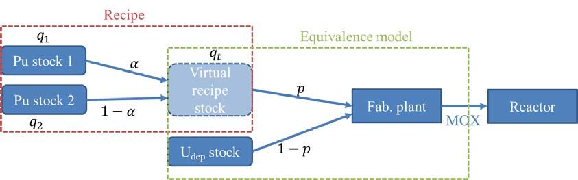
Let us consider the simplest example of MOX fuel fabrication from depleted uranium and two stocks of
separated plutonium. Let and be two isotopic qualities in separated plutonium buffers, with
defined as the ratio of the mass of fissile isotopes of Pu over the mass of Pu and 241Am in stock :
= + ( ) + .
The COSI7 recipe also defines a target quality that must be reached in the fresh fuel. The behavior of
the recipe is to pick the adequate mass of separated material mass in both stocks in order to reach the
target quality qt, thus replacing a series of micro-optimizations of the dataset. We remark that the total
mass to pick is not pre-determined as it depends on the Pu content in fresh fuel which is evaluated by the
equivalence model. Fig. 4 illustrates the recipe and equivalence process. First the recipe evaluates the
fraction of separated materials taken from the first stock as a function of ( , ) such that the virtual
recipe stock quality is . Then the equivalence model evaluates the plutonium content as a function of
the isotopic compositions of the virtual recipe stock and the depleted uranium stock.
Figure 4. Recipe and equivalence processes in fresh fuel fabrication.
Fig. 5 illustrates the application of recipes to PWR MOX fuel fabrication using plutonium separated from
both spent UOX fuel and spent MOX fuel. The plutonium quality in the Pu ex MOX feed is much lower
than in the Pu ex UOX feed. Without using a recipe, the plutonium quality at MOX fabrication shows two
distinct and generally unwanted trends:
x Short-term fluctuations due to the random nature of a batch-wise Pu feed;
x Long-term drift due to scenario dynamics (e.g. plutonium ageing).
Those trends are compensated using the recipe model. In this case, the recipe model setpoint is providing
a Pu feed with 60% quality.
7EPJ Web of Conferences 247, 13001 (2021) https://doi.org/10.1051/epjconf/202124713001
PHYSOR2020
Figure 5. Application of recipe model to PWR MOX fuel fabrication.
Recipes are compatible with both on-demand reprocessing and fixed capacity reprocessing plant models.
They can be adapted to match other criteria than the target quality such as isotopic composition, etc. They
provide the user with a new tool to model constrained fabrication processes which cannot be modeled
using previous versions of COSI6.
4. CONCLUSIONS AND PERSPECTIVES
The fuel cycle scenario code COSI7 was developed in order to answer demands from the fuel cycle
community, falling into two groups: improving the user experience and providing new models to give
more options to fine-tune scenarios.
Because the task of making and optimizing scenarios is very intensive in terms of engineering efforts,
improving the user experience for scenario-makers was a priority. Many improvements over the previous
version of COSI were implemented, including an internal dataset search engine, streamed post-processing
functions, client-server architecture with shared cache. These improvements are expected to ease dataset
implementation, scenario simulation and scenario analysis.
Several new physical models were also implemented in COSI7, designed in order to give the user the
possibility to model even more complex yet realistic scenarios. For instance, the new implementation of
recipes guarantees a given plutonium quality at fuel fabrication.
COSI7 supersedes COSI6 as the CEA reference nuclear fuel cycle simulation tool starting January 2020,
and will be used to model the future nuclear fuel cycle scenarios in support of French stakeholders and
decision-makers, including the scenarios associated with the French Multi-year Energy Plan (PPE).
ACKNOWLEDGMENTS
COSI7 development was funded by CEA project ACy/STECY.
REFERENCES
1. C. Coquelet-Pascal, M. Tiphine, G. Krivtchik, D. Freynet, C. Cany, R. Eschbach, C. Chabert,
“COSI6 : A Tool for Nuclear Transition Scenario Studies and Application to SFR Deployment
Scenarios with Minor Actinide Transmutation”, Nuclear Technology, Vol.192 (issue 2), pp.91-110
(2015)
2. G. Krivtchik, C. Coquelet-Pascal, P. Blaise, C. Garzenne, J. Le Mer, “Development of Surrogate
Models of the Evolution Code for Uncertainty Propagation in Scenario Studies”, Proc. Int. Conf. SNA
& MC 2013, Paris, France, October 27-31, 2013.
8EPJ Web of Conferences 247, 13001 (2021) https://doi.org/10.1051/epjconf/202124713001
PHYSOR2020
3. G. Krivtchik, R. Eschbach, G. Martin, M. Tiphine, D. Freynet, R. Girieud, P. Miranda, “COSI6: A
Tool for Nuclear Transition Scenario Studies”, Technical Workshop on Nuclear Cycle Simulation (TW
on NCS), Paris, France, July 6-8, 2016.
4. J.-M. Vidal et. al., “CESAR5.3 : A Code for Nuclear Fuel and Waste Characterization with Associated
Qualification”, Proc. Waste Management 2012 Conf. (WM2012), Phoenix, Arizona, February 26-
March 1, 2012.
9You can also read