2019 SkillsUSA Challenge Guide - Additive Manufacturing in Robotics on the Factory Floor - SME
←
→
Page content transcription
If your browser does not render page correctly, please read the page content below
2019 SkillsUSA
   Challenge Guide
Additive Manufacturing in
     Robotics on the
      Factory Floor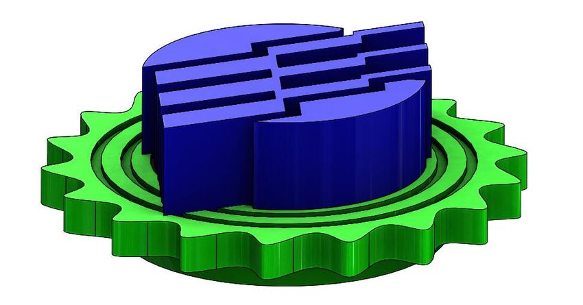
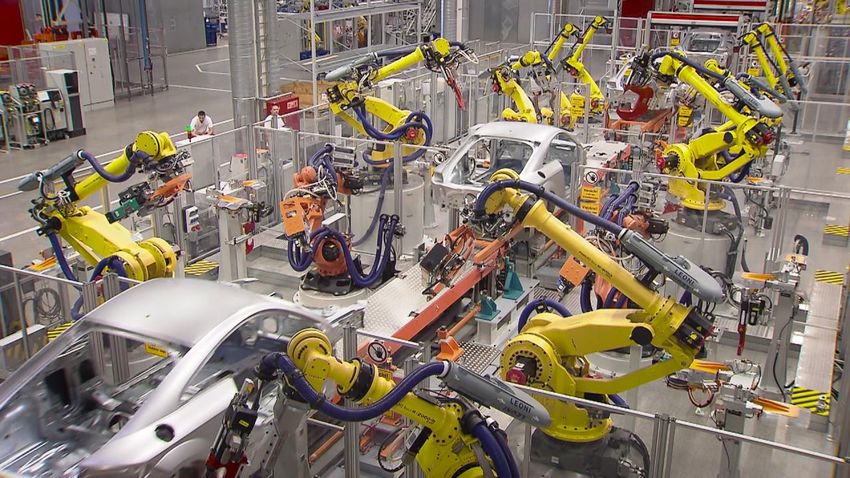
Challenge Overview
Introduction
Additive manufacturing/3D printing is changing the way things are made. From the rapid
prototyping lab all the way to the manufacturing floor. Companies in the automotive, aerospace
and consumer goods industries are leaning into an era of Industry 4.0, a technological playing
field where additive augments other technologies like robotics to provide higher throughput.
Shave days off production cycles. Remove complexity from final assembly. Produce lightweight,
high-strength structures. Compete in high-pace markets better. Thanks to the ability to easily
add customization and design with complexity, the path to market can be quicker and more
efficient today than ever before.

Traditional approaches to manufacturing are no longer the only way to bring your product to
market. Additive manufacturing is rapid compared to traditional forms of manufacturing and this
allows for multiple design iterations in which designs can be tested and improvements can be
made immediately.

Image: Fanuc Robots & 3D Printed Manufacturing Aides Used on the Automotive Assembly Line
Challenge Goal
The goal of this challenge is to demonstrate additive manufacturing skills by designing and
fabricating and applying an end of arm tool (EOAT) in a simulated real-life manufacturing
robotics scenario.By working with the design constraints of purpose, time, materials and a pre-
programmed robotics program, participants will demonstrate their ability to conceptualize,
design, iterate, and apply a 3D printed tool to a real-life manufacturing scenario.
Successful completion of the competition is defined as a well-documented, well-designed Tool
that, aided by a Robot running a pre-installed Program, repeatably places an Emblem on a
Target in the correct position and orientation.

Challenge Background
Each competing team represents members manufacturing engineering group at an automotive
manufacturer. As a manufacturing engineer working on a full-production sedan assembly line,
you are responsible for improving the repeatability and speed of car assemblies.
The issue of placing the vehicle badge precisely onto the back bumper of the car has been
brought up several times. This process involves operators manually picking up the manufacturer
logo emblem from a supply track and then placing the emblem onto a target location on the
vehicle body. It’s been a complaint for years that this operation is a repetitive task that has a
high rework rate (low repeatability) and low utilization (waste of operator time). During a recent
process efficiency meeting, the automation of this emblem placement activity has been
prioritized, and you have suggested that a robot with a 3D printed end-of-arm tool running a
program that repeats for each panel to be treated may be right path forward.

Challenge Description
To test a brilliant concept of the robotic emblem placement program, competing teams are using
simulated Components of the automotive manufacturing environment:
   ●   An Emblem that is approximately the same size and weight of the real-life emblem, but
       with magnets instead of adhesive.
   ●   A Track that locates the Emblem in approximately the same place each time.
   ●   A Frame made of 80/20 framing onto which the Target is permanently affixed
   ●   A Target which is placed at the right height and location with respect to the Track.
   ●   A Robot that will pick up the Emblem from the Track and place it on the Target.
   ●   An Adapter that is permanently mounted to the Robot that provides mounting points for
       the end-of-arm Tool.
   ●   A Program that the robot is running that can be triggered at any time to pick up an
       Emblem from the Track.
   ●   Rubber Bands of which 2x may be used in the Tool design.
The teams’ task in this competition is to take the provided Components (Emblem, Track, Target,
Robot, and Program), and develop a Tool made of 3D printed parts and rubber bands that
completes the automated concept.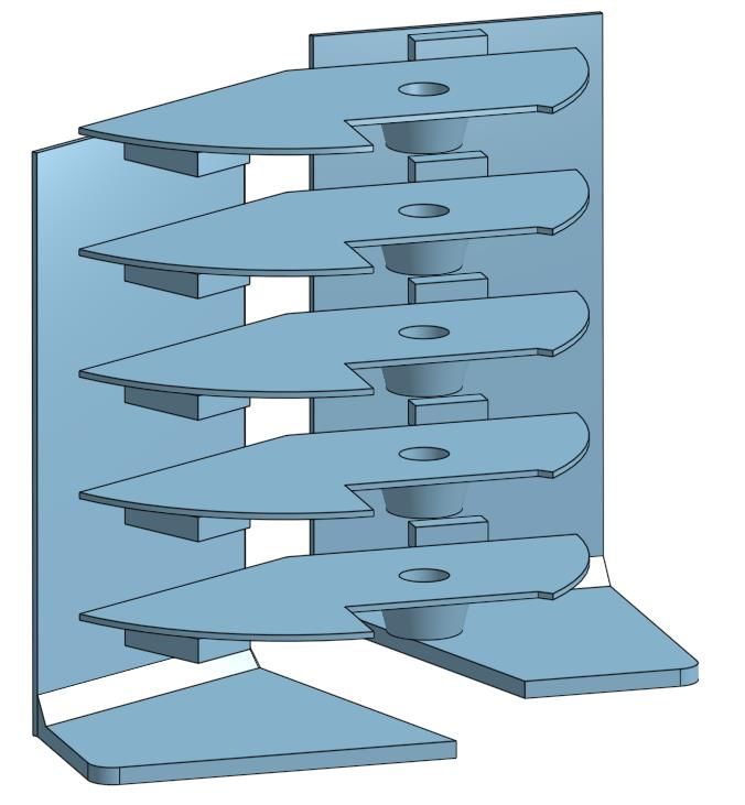
Component Kits
The competition components are located at the testing area and at desks for designing.
Testing Area Component Kit (TACK) is all equipment located at the actual competition testing
location. Breaking components of the TACK will result in penalties as outlined in the scoring
rubric. The TACK includes:
   ●   5x Emblems
   ●   1x Track
   ●   1x Target (on a platform)
   ●   1x Robot
   ●   2x Adapters (2x mounted onto the robot)
   ●   1x Program (running on the robot)
   ●   0x Rubber Bands (in Design Areas only)
   ●   0x USB Sticks
Design Area Component Kit (DACK) is all equipment provided to each team at the beginning
of the competition. There is no penalty for breaking components of the DACK but it will be more
difficult to test and design parts if DACK pieces are broken. The DACK includes:
   ●   1x Emblem (magnet is removed)
   ●   0x Track
   ●   0x Target
   ●   0x Robot
   ●   1x Adapters (for design and Tool testing purposes)
   ●   0x Program (on Robot at TACK only)
   ●   2x Rubber Bands (extras will be provided until competition supply runs out).
   ●   1x USB Stick (provided by teams)
Component Details: Emblem
The most important Component is the Emblem. The Emblem is the object to be picked up by
the Robot running a pre-set Program and placed on the Target. The actual automotive emblems
are applied with pressure-activated adhesives, but the simulated Emblem in the concept is a 3D
printed plastic Emblem with the SkillsUSA logo on it with a magnet on the back.

Above: Various dimensions of the Emblem             Above (visual only): Blue = “Logo”, Green = “Base”

Description of the Component
    ●    The Emblem Base (highlighted green) is the serrated disc and everything below it
         (including the magnet and tapered magnet holder). The Emblem Base has an
         approximate diameter of 1.5 inches, but at any point the diameter may be larger or
         smaller due to the teeth on the Base disc.
    ●    The Emblem Logo (highlighted blue) is the clear and red components of the Emblem
         above the Base. The largest diameter of the base is 1.36 inches (across the SkillsUSA
         logo) and the smallest diameter is 0.96 inches (across the clear boss).
Notes on Scoring
    ●    Extra points are awarded for programs that avoid touching the Logo (on the physical
         object the clear and red regions) of the Emblem. See scoring guide for details.
Kit Components
    ●    There are 5x magnetic Emblems in each Testing Area Component Kit
            ○ As with all TACK Components, there is a penalty for breaking a TACK Emblem.
    ●    There is 1x non-magnetic Emblems in each Design Area Component Kit.
            ○ As with all DACK Components, broken DACK Emblems will not be replaced.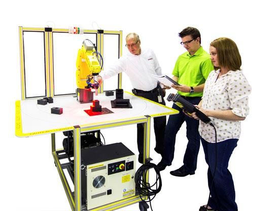
Component Details: Track
The Track is the Component that positions the Emblem before the Program is run. In the final
installation of the robotic assembly, the track delivery system will be made from industrial
framing and deliver the Emblem from another area of the production line. For the purposes of
this concept and competition, the Track transports the Emblem a short distance to simulate the
arrival of the Emblem for placement.

Above: The overall dimensions of the Track                              Above: The rails and bumpers of the Track

Above: There is variability in the Emblem’s final position.   Above: The Track is about 22 inches in total length.

Description of the Component
     ●    The Track transports the Emblem down a 22-inch-long track, descending about 7 ¾
          inches in height and moving the Emblem towards the robot by about 18 ¼ inches.
     ●    The Emblem descends the track on rails that touch the disc on the Emblem Base of the
          not the Logo or magnet boss.
Notes on Scoring
     ●    When the Emblem has reached the bottom of the Track, it will be located somewhere
          between the end of the rails and the bumper pins (both shown in black above). This
          variance is approximately 1 ⅜ inches and the arm must account for this for repeatable
          success. See scoring guide for details.
Kit Components
     ●    Each TACK includes 1x Track
             ○ As with all TACK Components, there is a penalty for breaking a TACK Track.
     ●    There are no Tracks in the DACK.
Component Details: Target & Frame
The Target is the destination of the Emblem during the Robot Program. The Target does not
ever move. In the center of the Emblem is a magnet that will attract the Emblem to simulate
adhesive during the real robotics application.

                                             Above: The Emblem shown is in the perfect Orientation.

Description of the Component
   ●     The Target has a magnet that will mate to the Emblem.
   ●     The “tip” of the Emblem Logo will line up with a mark on the Target for full points.

Notes on Scoring
   ●     There are two important components to the score as it relates to the Target:
            ○ “Placement” is based on whether the Emblem ends up on the Target after the
                Robot’s Program has finished.
            ○ “Orientation” is measured in “teeth” is based on the number of Emblem teeth
                between the Target’s black Orientation indicator and the Emblem’s. The number
                of teeth will be rounded by the judge’s discretion.
                    ■ Examples of judging rules below:

  Orientation off by 1 Tooth   Orientation off by 2 Teeth      Orientation off by 0 Teeth    Orientation off by 7 Teeth

Kit Components
   ●     Each TACK includes 1x Track
            ○ As with all TACK Components, there is a penalty for breaking a TACK Target.
   ●     There are no Targets in the DACK.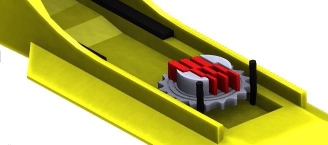
Component Details: Robot & Program
The Robot for this competition and concept demonstration is a Fanuc educational robot. The
Program has been already created.

                                                                  +
                                                                  +  +
Above: The Fanuc robot used in this contest.
                                                                 - - -
                                               Above: XYZ definitions and grab position of the Robot

Description of the Component .
    ●    The Robot is at the XYZ location [0” 0” 0”] when it is in the “grab position” before closing.
    ●    The Robot performs a close-range procedure just before moving to the [0” 0” 0”] grab
         position:
            ○ [-2.25” -1” 0.2”]
            ○ [-2.25” 0.2” 0.2”]
            ○ [0” 0” 3.5”]
            ○ [0” 0” 0”] “grab position”
    ●    Note that the starting location of the Robot as well as the locations of the Track and
         Target are provided as a .STEP file in your DACK USB drive

Notes on Scoring
    ●    Note that it will be important to observe the Robot and take careful note of the above
         Program to ensure that the Robot does not crash into anything during the program.
            ○ If the Robot does crash during a program, it’s likely that a TACK item or the
                team’s Tool will break.
Kit Components
    ●    Each TACK includes 1x Robot running the Program
            ○ As with all TACK Components, there is a penalty for breaking a TACK Emblem.
    ●    There are no Robots in the DACK.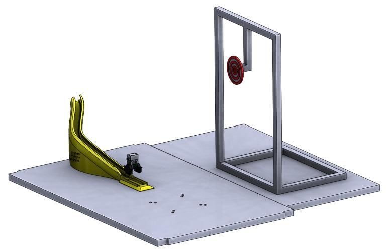
Component Details: Adapter
The standard actuator attached to the Robot is a Schunk actuator that is permanently attached
to 3D printed Adapters made out of Ultem 1010. The purpose of the Adapters is to provide
various different connection points that teams may use to fix their Tool onto the Robot.

Above: The Adapters fit onto the Schunk actuator      1.1                             1.6
                                                   Above: each Adapter moves 0.25 inches when closing.

Description of the Component
    ●    An Adapter fits onto each side
    ●    The Adapters are provided at the TACK and each DACK includes 1x Adapter.
    ●    If you believe that one of the TACK Adapters is worn or broken, alert competition staff
         immediately, as these are essential for fair play.
Notes on Scoring
    ●    The Tool may not affix to anything but the Adapter.
    ●    The Tool may not harm or alter the Adapters (breaking TACK components will be met
         with a penalty.
Kit Components
    ●    Each TACK includes 2x Adapters
            ○ As with all TACK Components, there is a penalty for breaking a TACK Adapter.
    ●    There will be 1x non-kitted Schunk actuator with Adapters fitted for experimentation and
         measurement to be shared by all teams. It will be located at one of the TACK locations.
    ●    Each DACK includes 1x Adapter for measurement and fitting purposes.
Component Details: Rubber Bands
Up to 2x complete, uncut Rubber Bands (provided) may be used in the final Tool.

                                       ¼
                                                                      2.5
Above: The rubber bands are size 62.   Above: Dimensions of a size 62 rubber band

Description of the Component .
    ●    Use of Rubber Bands must obey the following rules:
            ○ Rubber Bands may not affix to anything except the Tool or Adapter (not the
                Track, Target, Robot, etc.)
            ○ They may not be cut or broken (though they may be tied, including tied together)
Kit Components
    ●    Each DACK includes 2x Rubber Bands
            ○ Rubber Bands may be replaced (Up to 8x total per team) before supplies run out.
    ●    There are no Rubber Bands at the TACK

Component Details: USB Drive
Each team will receive the following files onto their USB drive at the beginning of the
competition:
    ●    DACK_Robot_BEGIN_Locations.STEP
            ○ This STEP file has the geometry & relative positioning of the Track, Target, and
               BEGIN location of the Robot and Adapters
    ●    [COMPONENT].STEP (4x)
            ○ A STEP file of the following Components: Ramp, Emblem, Adapter, Target
    ●    2019_Challenge_Guide.pdf
            ○ A pdf of this challenge guide
    ●    2019_Scoring_Guide.pdf
            ○ A pdf of the scoring guide
Other Tool Requirements
Each team needs to carefully read through the Component Details above and observe the
Robot Program carefully… there is a lot of room for creativity for solving the presented problem!
However, each Tool must obey the following rules. Disobedience of these rules will lead to
significant point penalties or disqualification of the Functional Testing portion of the score.
● The Tool must have the Team Number legibly printed onto it
○ This is a scored requirement that makes feasible 3D printing many Tools
overnight (also mentioned in Print Deliverable Specifications below).
● The Tool may only consist of 3D printed parts and Rubber Bands
○ May consist of any part of Tuesday’s print, Wednesday’s print, and/or both.
● The Tool may make use of only up to 2x Rubber Bands
○ (See Component Details: Rubber Band)
● The Tool may only affix to the Adapters provided
○ (See Component Details: Adapter)
○ The Tool must remain attached to the Adapter(s) throughout the entire Program.Challenge Agenda
Day 1, Tuesday
Tuesday is Day 1 of the competition. There will be 3.5 hours of design time available to
contestants to design for their first of two opportunities to 3D print overnight. During the design
time on Tuesday, the TACK (See Kit Descriptions) will be available for measurement and
planning.
Reminders:
- Teams should document their journey in their engineering notebook (see judging rubric
for details). This notebook may be taken home each night to finalize documentation.
- At the end of the design time, contestants must submit a file folder on their USB drive
that matches the Print Deliverable Specifications specified below.
Day 2, Wednesday
Wednesday is Day 2 of the competition. Students will receive their 3D printed parts from
Tuesday’s design efforts to test. Students will receive 3 more hours of design time; iterations will
be 3D printed overnight. During the design time on Wednesday, the TACK will be available for
part testing.
Reminders:
- Teams should document their journey in their engineering notebook (see judging rubric
for details). This notebook may be taken home each night to finalize documentation.
- At the end of the design time, contestants must submit a file folder on their USB drive
that matches the Print Deliverable Specifications specified below.
Day 3, Thursday
Thursday is presentation day. At the end of the day on Wednesday, students were given their
“judging time.” Students are allowed to show up at the contest location 45 minutes prior to their
judging time. Upon arrival, students will check in and receive their printed part from Wednesday.
Students are allowed to inspect their Wednesday print and perform any sanding or assembly
(as well as testing) desired before judging.
When the judges are ready (no sooner than the “judging time”), the team will be called to the
presentation table, given 10 minutes to present their process, engineering notebook and printed
designs. Judges will ask necessary questions to fully score student design before moving to the
functional testing portion of judging View the Judging Procedure below for details on the
requirements of the presentation and judging. Students should fully review the Judging Rubric
below to assist crafting their final presentation.Print Deliverable Specifications
On Tuesday and Wednesday, students will submit files to be 3D printed overnight (see agenda
above). Below is the deliverable that must be submitted on your USB drive to have parts 3D
printed.
File Folder Specifications
● A file folder titled “Team [#] - [Day of Week] Submission” (fill in “[#]” with team number)
● Within the above folder, include the following files (all files must be formatted in this way:
“Team [#] - [Day of Week] - [File Description]”):
○ a GrabCAD Print Project (.print) file saved at these settings:
■ Machine: F370
■ Slice Height: 0.010 inches
■ Material: ABS-M30
○ all STL (.stl) files of design (ensure correct mm/in scaling)
○ native CAD files of design
○ a Notepad text document (.txt) (not Word, .docx, etc.) document very clearly
explaining the orientation of each part and infill style: sparse high density, sparse
low density, or solid (this is because the administrators likely will need to
rearrange files for actual printing).
■ To create a .txt file, in a folder Right-click > New > Text Document
■ Near the top of the .txt file include the estimated time for the .print file that
was submitted.
Design Specifications
● The Team Number must be legibly 3D printed into at least 1 component of each
evening’s build.
● The total print must fit in a build envelope of 4.7”(L) x 4.7”(W) x 4.7”(H)
● Review rubric on material usage judging criteria
● The print must not exceed the time and material allowances referenced in the scoring
guide. Parts that do not follow this requirement may not be printed overnight without
notice. Double-check your .print file for resource consumption before submission each
day.Judging Procedure
Presentation
1. Prior to judging time, teams must ensure that their Tool is fully assembled and ready to
attach to the Adapters. Note: geometry-altering changes to Tools are not permitted
between the presentation and functional testing.
2. The team will give a 10-minute (no more) presentation on their design process. Leave
time for Judges to ask questions.
a. Optional visual aids may include the following:
i. Powerpoint (or similar program) slides
ii. Your engineering notebook
iii. 3D printed parts printed from Tuesday and Wednesday
b. Review the rubric below to ensure that your Presentation & Engineering
Notebook cover all judged points. (review rubric for Engineering Notebook
criteria) Use your engineering notebook to demonstrate:
i. Design Process (How did you go about brainstorming and designing your
parts? How did you effectively respond to Tuesday’s print results during
Wednesday’s design time?
ii. Team Functions, Roles and Responsibilities (How did you split up roles
and take advantage of each other’s strengths?)
iii. Limitations and Lessons Learned (Did anything go wrong during the past
few days that was preventable? Where does your design fall short? What
would you ask the patient if you had the opportunity?)
Testing
3. Once the Presentation is over, the group will move to the TACK; the team will be given
30 seconds to attach their Tool to the Adapters.
a. Review the Tool Rules above for legal geometries and installation.
4. This testing procedure will be repeated 10 times:
a. The judge will place a random into the Track (not forcefully).
i. There may be no preference of particular Emblems or Tracks for use
during Functional Testing
b. If the Emblem falls out of the Track or out of alignment (see the legal range of
position in Component Details: Track), then the Judge will begin again with a new
Emblem.
c. Once the Emblem is motionless at the base of the Track, the judge will initiate
the Program.
d. Based on the result of the Program, points will be awarded for Placement and
Orientation (see details in Rubric and Component Details: Target).’
e. You will be allowed to “adjust” the placement of your Tool up to 3 times at a point
penalty throughout the 10 testing runs.2019 SkillsUSA Mini Challenge Guide
The “Mini Challenge” is a short activity that tests a different area of competitors’ knowledge of
additive manufacturing. This year, the focus is the “Economics of Additive Manufacturing.” How
well do you understand 3D printing and economies of scale?
Procedure and Rules
1. Read the scenario and questions below. Competitors will have 60 minutes to complete
the Mini Challenge.
2. Fulfill the deliverable as described in Deliverable Instructions (you’ll need the separate
Scheduling Sheet for your deliverable).
Background: Incoming Requests
You work at a technology company called SixStar as an FDM lab technician. Although there are
internal departments at SixStar that use your 3D printing services, a large part of your lab’s
activity is doing paid services for outside organizations.
On this particular Monday, you’re in early on at 4:15am to get the shop prepared for the rest of
your staff to arrive at 6:00am. This should be a quiet week because all your printers are running
with important jobs (and will be running all week non-stop) except a Stratasys F370 which is
sitting idle.
All of a sudden, at 5:00am exactly, three urgent requests come in from outside companies. All
three are well-respected clients (LunarTech, FabricaTech, and SoarTech), and they all seem to
have urgent, expensive projects to finish by 5pm on Friday!
...that's always how it happens on Mondays...Background: LunarTech Request
● Customer: LunarTech
● Part Name: CartoonRocketv2.step
● Material: ASA
● Layer Height: See instructions
● Needed Quantity: 2
● Print instructions: “SixStar Lab, it’s Jason at LunarTech up the highway! Super urgent,
need to come pick this up by 5pm Friday… it’s a cosmetic part so it doesn’t need to be
strong at all, but the better the resolution of the print, the more I’m willing to pay since it
will need less sanding on our end! If you can print it high-resolution, I’ll pay $3000; for
medium res I’ll pay $1500, and for low-res I’ll pay $500.”Background: FabricaTech Request
● Customer: FabricaTech
● Part Name: PN55Fixture.step
● Material: ASA
● Layer Height: 0.013”
● Needed Quantity: 2
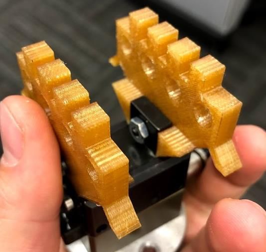
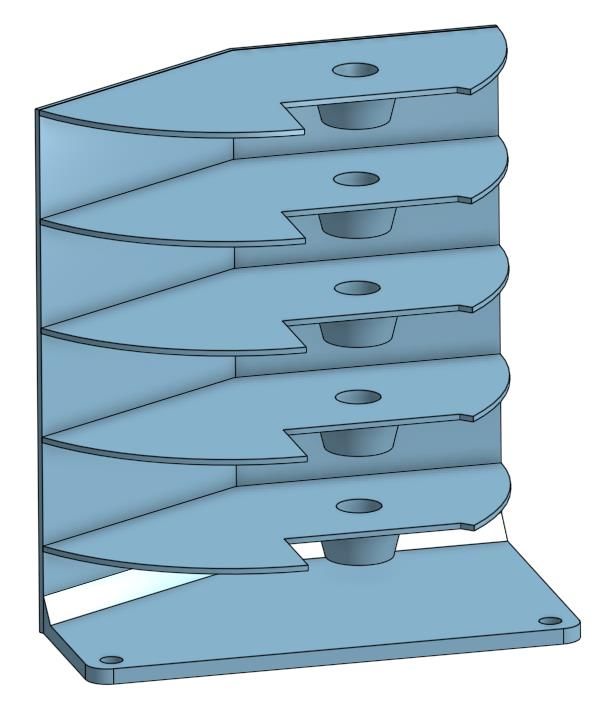
● Print instructions: “Hey SixStar team, this is Joan from FabricaTech Operations in
downtown. Remember how we talked about those 3D printed robotic staging shelf? I got
last-minute approval yesterday to print those for a line pilot next week. I remember you
mentioned that they will print faster when printed in multiple pieces… but it’s going to
cost me something to assemble, so I’d rather have it together. I really need of them by
end-of-day Friday...5pm if you can. I’m willing to pay $3000 if you print it assembled and
$1500 if it’s unassembled.”Background: SoarTech Request
● Customer: SoarTech
● Part Name: 3967-03-02AngleLink.step
● Material: ASA
● Layer Height: 0.010”
● Quantity: at least 200
● Print instructions: “SixStar, this is SoarTech down the street… we just got a HUGE order
for our Link3967 systems… I’ll need 4,000 of these angle links ready by Friday at noon
for pickup. I know you can’t make them all… but I need (NEEEEEED) at least 200!
We’ve dialed in the settings: ASA 0.010” solid, so please just print as many as you can!
Willing to pay $20/pop since it’s urgent.”Background: Organizing the Data
As the machines of your shop whir and churn on parts, you take a sip of your coffee and stare at
the lone F370.
It’s now 5:15am.
You’re nervous, because the three customers (LunarTech, FabricaTech, and LinkTech) are all
important customers… not fulfilling any of their orders completely will probably damage
SixStar’s relationship with that customer.
You guess that not completely fulfilling any of the orders will probably lose you 5% of that
company’s business for the next year. You thumb through last year’s books, looking for the
revenue from each of these businesses:
● LunarTech: $30,000
○ So 5% lost sales = -$1,500
● FabricaTech: $20,000
○ So 5% lost sales = -$1,000
● SoarTech: $10,000
○ So 5% lost sales = -$500
After thinking things through, you decide there are a few different “Options” that you can print to
fulfill these orders. Each Option satisfies By running through the Print Instructions, you come up
with the following Options chart.
Figure MC-1The Challenge
It’s now 5:30am. You’ve got 30 minutes until your staff come in and you put your plan into
action.
You drain the rest of your coffee.
It’s now up to you to design a number of Builds that the F370 will run throughout the week. Each
Build will consist of 1 or more Options from Figure MC-1. The Builds must be scheduled in the
Scheduling Sheet separate from this guide.
Build Creation Rules
● Build Size: Each Build may not consist of Options that require more than 1 full Tray (see
Tray Space Needed column in MC-1).
○ Summing Times: The time required for two different options is approximated to
be simply the sum of the Options’ times. (Example: time required for F1 + S1 =
30 hours)
● Matching Settings: Options within a single Build must have matching Settings (See
Settings column in MC-1)
● Scheduling: Lab staff is only available 6am - 2pm each day to remove a Build and start
another one.
○ Instant Changeovers: For the purposes of scheduling, there are zero (0) hours
required in between Builds (even if changing layer height Settings).
● Support Removal: Every item in all Options requires at least 8 hours for support
removal and packaging. Therefore, any parts that aren’t finished at least 8 hours before
5pm Friday will not be delivered.
Deliverable Instructions
Fill out a Scheduling Sheet (Separate from this Mini Challenge Guide). Turn the Scheduling
Sheet in at the end of the allowed time. No late submissions.
Scoring Rubric
___/20 points - None of the Build size, settings, or scheduling rules (in section Build Creation
Rules) were violated.
___/80 points - Net Revenue generation from Scheduling Sheet
● 80/80: $14,500 or higher
● 60/80: $13,500 to $14,499
● 40/80: $10,000 to $13,499
● 0/80: under $10,000Midnight
Scheduling Sheet Team #________
Noon
6pm
6am
Instructions: Fill in Builds with at least one Option Code (i.e.
L1, S2). You do not need to use all eight Builds. Calculate Net
Revenue by subtracting Penalties from Gross Revenue.
Build Schedule
Option Codes Build Time Build Revenue
Monday Tuesday Wednesday Thursday Friday
Example L2 S1 18 $2500
Build 1
Build 2
Build 3
Build 4
Build 5
Build 6
Build 7
Build 8
Total the “Build Rev.” column to find
Gross Revenue Under-Fulfillment LunarTech
(less than qty 2)
FabricaTech
(less than qty 2)
SoarTech
(less than qty 200)
Net Revenue
$________ Penalties (circle): $1,500 $1,000 $1,500 $________You can also read