Visible Patient Planning - Version: 1.0.12 February 2019
←
→
Page content transcription
If your browser does not render page correctly, please read the page content below
Visible Patient Planning
                                 Version: 1.0.12
                                  February 2019

                          User Documentation

                            Unique Device Identifier (UDI)
                         *+B373VPS10120/$$71.0.12C*

Software instructions for use (in english and other avaiblable languages) can be downloaded
at https://www.visiblepatient.com/go/planning-user-manual.
Software instructions for use in english are available in the “Help” menu of the software.
Hard copy of instructions for use can be requested at no additional cost and delivered to the
customer within 7 working days.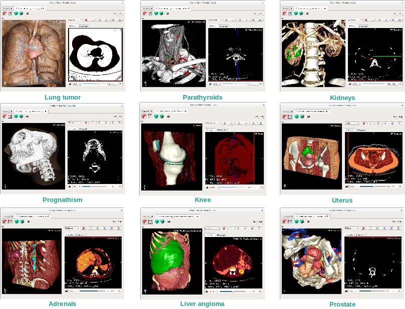
SDM-UM-VPSuite-Planning-1.0.12-en_v1                                                            Visible Patient Planning

                                                                                       Prescription use only

  CAUTION: Federal law restricts this device to sale by or on the order of a physician.

                                       Indications for use

Visible Patient Suite is medical imaging software that is intended to provide trained medical professionals with tools to
aid them in reading, interpreting, reporting, and treatment planning. Visible Patient Suite accepts DICOM compliant
medical images acquired from a variety of imaging devices, including CT, MR.
This product is not intended for use with or for the primary diagnostic interpretation of Mammography images.
The software provides several categories of tools. It includes basic imaging tools for general images, including 2D
viewing, volume rendering and 3D volume viewing, orthogonal Multi-Planar Reconstructions (MPR), image fusion,
surface rendering, measurements, reporting, storing, general image management and administration tools, etc.
It includes a basic image processing workflow and a custom UI to segment anatomical structures, which are visible in
the image data (bones, organs, vascular/airway structures, etc.), including interactive segmentation tools, basic image
filters, etc.
It also includes detection and labeling tools of organ segments (liver, lungs and kidneys), including path definition
through vascular/airway, approximation of vascular/airway territories from tubular structures and interactive labeling.
The software is designed to be used by trained professionals (including physicians, surgeons and technicians) and is
intended to assist the clinician who is solely responsible for making all final patient management decisions.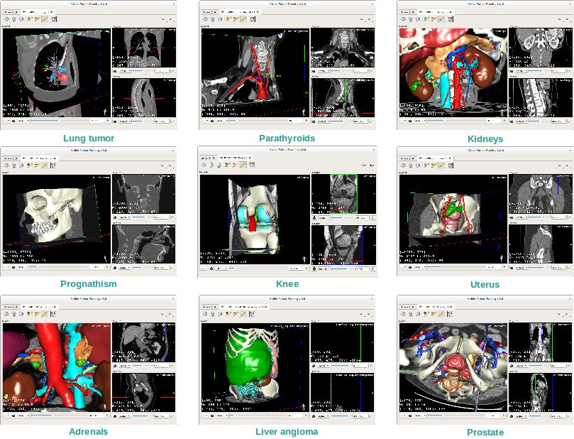
SDM-UM-VPSuite-Planning-1.0.12-en_v1                                                         Visible Patient Planning

                                             Approvals
               This medical device software is CE marked and FDA cleared. It can therefore be used in clini-
               cal routine and/or for patient care in member states of the European Union where national regulations
               are respected and the USA (complete list of countries available at https://www.visiblepatient.com/go/
               planning-user-manual).

               Use of this software is not allowed in countries not mentioned in the list above.

               In these countries, the software is considered as a prototype software and its use is limited to demonstration,
               research, or educational purposes. Any other use is strictly prohibited, clinical use on humans in particular.

              Visible Patient SAS
              RCS Strasbourg TI 794 458 125
              1 place de l’hôpital
              67000 Strasbourg, FRANCE
              Share capital: 58.333 C

 Contact      Email: support@visiblepatient.com
              Phone: +33 (0)3 90 22 42 00
              Website: www.visiblepatient.com

 US Agent     STRATEGY Inc.
              805 Bennington Drive
              suite 200
              Raleigh, North Carolina 27615
              UNITED STATES
              Phone: +1 919 900 0718
              Fax: +1 919 977 0808
              Email: nancy.patterson@strategyinc.net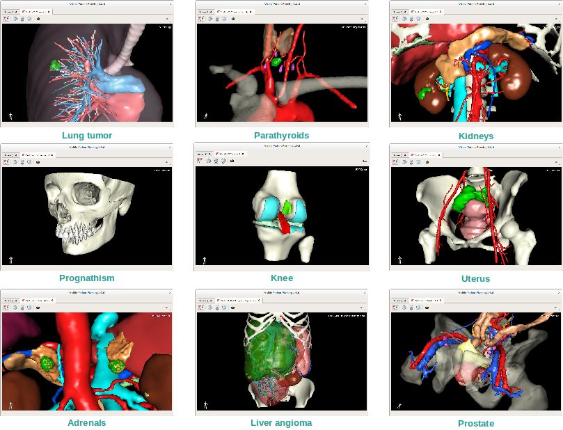
SDM-UM-VPSuite-Planning-1.0.12-en_v1 Visible Patient Planning
Contents

1   Indications for use                                                                                                                                                     7

2   Contraindication                                                                                                                                                        9

3   Cautions                                                                                                                                                                11
    3.1 General caution . . . . . . . . . . . . . . . . . . .   .   .   .   .   .   .   .   .   .   .   .   .   .   .   .   .   .   .   .   .   .   .   .   .   .   .   .   11
    3.2 Secure computing environment . . . . . . . . . .        .   .   .   .   .   .   .   .   .   .   .   .   .   .   .   .   .   .   .   .   .   .   .   .   .   .   .   11
    3.3 Visible Patient data transfer . . . . . . . . . . . .   .   .   .   .   .   .   .   .   .   .   .   .   .   .   .   .   .   .   .   .   .   .   .   .   .   .   .   11
    3.4 3D model with transparency visualization caution .      .   .   .   .   .   .   .   .   .   .   .   .   .   .   .   .   .   .   .   .   .   .   .   .   .   .   .   11
    3.5 Volume rendering caution . . . . . . . . . . . . .      .   .   .   .   .   .   .   .   .   .   .   .   .   .   .   .   .   .   .   .   .   .   .   .   .   .   .   12
    3.6 Anatomical structures volumes caution . . . . . .       .   .   .   .   .   .   .   .   .   .   .   .   .   .   .   .   .   .   .   .   .   .   .   .   .   .   .   12
    3.7 Organ segments visualization caution . . . . . . .      .   .   .   .   .   .   .   .   .   .   .   .   .   .   .   .   .   .   .   .   .   .   .   .   .   .   .   12
    3.8 Distance measurement caution . . . . . . . . . . .      .   .   .   .   .   .   .   .   .   .   .   .   .   .   .   .   .   .   .   .   .   .   .   .   .   .   .   12

4   Technological Characteristics                                                                                                                                           13
    4.1 System requirements and characteristics . . . . . . . .         .   .   .   .   .   .   .   .   .   .   .   .   .   .   .   .   .   .   .   .   .   .   .   .   .   13
         4.1.1    PC - Minimal System Requirements . . . . .            .   .   .   .   .   .   .   .   .   .   .   .   .   .   .   .   .   .   .   .   .   .   .   .   .   13
         4.1.2    PC - Recommended System Requirements . .              .   .   .   .   .   .   .   .   .   .   .   .   .   .   .   .   .   .   .   .   .   .   .   .   .   13
         4.1.3    Mac - Minimal System Requirements . . . .             .   .   .   .   .   .   .   .   .   .   .   .   .   .   .   .   .   .   .   .   .   .   .   .   .   14
         4.1.4    Mac - Recommended System Requirements .               .   .   .   .   .   .   .   .   .   .   .   .   .   .   .   .   .   .   .   .   .   .   .   .   .   14
    4.2 Software overview . . . . . . . . . . . . . . . . . . .         .   .   .   .   .   .   .   .   .   .   .   .   .   .   .   .   .   .   .   .   .   .   .   .   .   14
         4.2.1    Visible Patient Planning . . . . . . . . . . . .      .   .   .   .   .   .   .   .   .   .   .   .   .   .   .   .   .   .   .   .   .   .   .   .   .   14
    4.3 Software modules . . . . . . . . . . . . . . . . . . .          .   .   .   .   .   .   .   .   .   .   .   .   .   .   .   .   .   .   .   .   .   .   .   .   .   14
         4.3.1    Image DICOM reader (MR/CT) . . . . . . .              .   .   .   .   .   .   .   .   .   .   .   .   .   .   .   .   .   .   .   .   .   .   .   .   .   15
         4.3.2    Manual DICOM parser (MR/CT) . . . . . . .             .   .   .   .   .   .   .   .   .   .   .   .   .   .   .   .   .   .   .   .   .   .   .   .   .   15
         4.3.3    Visible Patient data reader/writer . . . . . . .      .   .   .   .   .   .   .   .   .   .   .   .   .   .   .   .   .   .   .   .   .   .   .   .   .   15
         4.3.4    2D image multi-planar representation (MPR)            .   .   .   .   .   .   .   .   .   .   .   .   .   .   .   .   .   .   .   .   .   .   .   .   .   15
         4.3.5    Image volume rendering . . . . . . . . . . .          .   .   .   .   .   .   .   .   .   .   .   .   .   .   .   .   .   .   .   .   .   .   .   .   .   15
         4.3.6    Anatomical atlas . . . . . . . . . . . . . . .        .   .   .   .   .   .   .   .   .   .   .   .   .   .   .   .   .   .   .   .   .   .   .   .   .   15
         4.3.7    3D model visualization . . . . . . . . . . . .        .   .   .   .   .   .   .   .   .   .   .   .   .   .   .   .   .   .   .   .   .   .   .   .   .   16
         4.3.8    3D model and image visualization . . . . . .          .   .   .   .   .   .   .   .   .   .   .   .   .   .   .   .   .   .   .   .   .   .   .   .   .   16
         4.3.9    Organ segments visualization . . . . . . . . .        .   .   .   .   .   .   .   .   .   .   .   .   .   .   .   .   .   .   .   .   .   .   .   .   .   16

5   Installation instructions                                                                                                                                               17
    5.1 Install Visible Patient Planning software . . . . . . . . . . . . . . . . . . . . . . . . . . . . . . . . .                                                         17

                                                                                                                                                                            5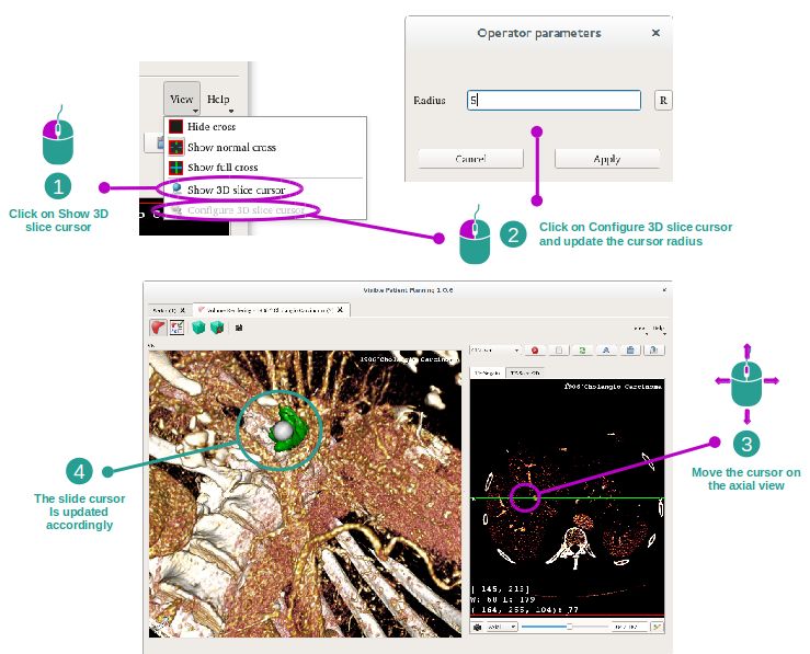
SDM-UM-VPSuite-Planning-1.0.12-en_v1                                                                                                  Visible Patient Planning

          5.1.1    How to install Visible Patient Planning on Windows . . . . . . . . . . . . . . . . . . . . . .                                                              17
          5.1.2    How to install Visible Patient Planning on Mac . . . . . . . . . . . . . . . . . . . . . . . .                                                              23

6   Operating instructions                                                                                                                                                     25
    6.1 How to load data . . . . . . . . . . . . . . . . .    .   .   .   .   .   .   .   .   .   .   .   .   .   .   .   .   .   .    .   .   .   .   .   .   .   .   .   .   25
    6.2 How to visualize an image . . . . . . . . . . . .     .   .   .   .   .   .   .   .   .   .   .   .   .   .   .   .   .   .    .   .   .   .   .   .   .   .   .   .   28
         6.2.1    Prerequisites . . . . . . . . . . . . . .   .   .   .   .   .   .   .   .   .   .   .   .   .   .   .   .   .   .    .   .   .   .   .   .   .   .   .   .   29
         6.2.2    Visualize the patient’s anatomy . . . . .   .   .   .   .   .   .   .   .   .   .   .   .   .   .   .   .   .   .    .   .   .   .   .   .   .   .   .   .   29
         6.2.3    Examples of other anatomical structures     .   .   .   .   .   .   .   .   .   .   .   .   .   .   .   .   .   .    .   .   .   .   .   .   .   .   .   .   32
         6.2.4    Additional information . . . . . . . . .    .   .   .   .   .   .   .   .   .   .   .   .   .   .   .   .   .   .    .   .   .   .   .   .   .   .   .   .   33
    6.3 How to visualize a 3D model . . . . . . . . . .       .   .   .   .   .   .   .   .   .   .   .   .   .   .   .   .   .   .    .   .   .   .   .   .   .   .   .   .   38
         6.3.1    Prerequisites . . . . . . . . . . . . . .   .   .   .   .   .   .   .   .   .   .   .   .   .   .   .   .   .   .    .   .   .   .   .   .   .   .   .   .   38
         6.3.2    Visualize the patient’s anatomy . . . . .   .   .   .   .   .   .   .   .   .   .   .   .   .   .   .   .   .   .    .   .   .   .   .   .   .   .   .   .   38
         6.3.3    Examples of other anatomical structures     .   .   .   .   .   .   .   .   .   .   .   .   .   .   .   .   .   .    .   .   .   .   .   .   .   .   .   .   43
         6.3.4    Additional information . . . . . . . . .    .   .   .   .   .   .   .   .   .   .   .   .   .   .   .   .   .   .    .   .   .   .   .   .   .   .   .   .   44
    6.4 How to visualize an image with a model . . . . .      .   .   .   .   .   .   .   .   .   .   .   .   .   .   .   .   .   .    .   .   .   .   .   .   .   .   .   .   47
         6.4.1    Prerequisites . . . . . . . . . . . . . .   .   .   .   .   .   .   .   .   .   .   .   .   .   .   .   .   .   .    .   .   .   .   .   .   .   .   .   .   47
         6.4.2    Visualize the patient’s anatomy . . . . .   .   .   .   .   .   .   .   .   .   .   .   .   .   .   .   .   .   .    .   .   .   .   .   .   .   .   .   .   47
         6.4.3    Examples of other anatomical structures     .   .   .   .   .   .   .   .   .   .   .   .   .   .   .   .   .   .    .   .   .   .   .   .   .   .   .   .   50
         6.4.4    Additional information . . . . . . . . .    .   .   .   .   .   .   .   .   .   .   .   .   .   .   .   .   .   .    .   .   .   .   .   .   .   .   .   .   51
    6.5 How to visualize a volume . . . . . . . . . . . .     .   .   .   .   .   .   .   .   .   .   .   .   .   .   .   .   .   .    .   .   .   .   .   .   .   .   .   .   55
         6.5.1    Prerequisites . . . . . . . . . . . . . .   .   .   .   .   .   .   .   .   .   .   .   .   .   .   .   .   .   .    .   .   .   .   .   .   .   .   .   .   55
         6.5.2    Visualize the patient’s anatomy . . . . .   .   .   .   .   .   .   .   .   .   .   .   .   .   .   .   .   .   .    .   .   .   .   .   .   .   .   .   .   55
         6.5.3    Examples of other anatomical structures     .   .   .   .   .   .   .   .   .   .   .   .   .   .   .   .   .   .    .   .   .   .   .   .   .   .   .   .   59
         6.5.4    Additional information . . . . . . . . .    .   .   .   .   .   .   .   .   .   .   .   .   .   .   .   .   .   .    .   .   .   .   .   .   .   .   .   .   60
    6.6 How to use the Anatomical Atlas Activity . . . .      .   .   .   .   .   .   .   .   .   .   .   .   .   .   .   .   .   .    .   .   .   .   .   .   .   .   .   .   61
         6.6.1    Prerequisites . . . . . . . . . . . . . .   .   .   .   .   .   .   .   .   .   .   .   .   .   .   .   .   .   .    .   .   .   .   .   .   .   .   .   .   61
         6.6.2    Visualize the patient’s anatomy . . . . .   .   .   .   .   .   .   .   .   .   .   .   .   .   .   .   .   .   .    .   .   .   .   .   .   .   .   .   .   62
         6.6.3    Examples of other anatomical structures     .   .   .   .   .   .   .   .   .   .   .   .   .   .   .   .   .   .    .   .   .   .   .   .   .   .   .   .   63
         6.6.4    Additional information . . . . . . . . .    .   .   .   .   .   .   .   .   .   .   .   .   .   .   .   .   .   .    .   .   .   .   .   .   .   .   .   .   64
    6.7 How to visualize organ segments . . . . . . . .       .   .   .   .   .   .   .   .   .   .   .   .   .   .   .   .   .   .    .   .   .   .   .   .   .   .   .   .   65
         6.7.1    Prerequisites . . . . . . . . . . . . . .   .   .   .   .   .   .   .   .   .   .   .   .   .   .   .   .   .   .    .   .   .   .   .   .   .   .   .   .   65
         6.7.2    Apply clips on an organ’s network . . .     .   .   .   .   .   .   .   .   .   .   .   .   .   .   .   .   .   .    .   .   .   .   .   .   .   .   .   .   66
         6.7.3    Examples of other anatomical structures     .   .   .   .   .   .   .   .   .   .   .   .   .   .   .   .   .   .    .   .   .   .   .   .   .   .   .   .   68
         6.7.4    Additional information . . . . . . . . .    .   .   .   .   .   .   .   .   .   .   .   .   .   .   .   .   .   .    .   .   .   .   .   .   .   .   .   .   68

7   Maintenance                                                                                                                                                                71
    7.1 Planning . . . . . . . . . . . . . . . . . . . . . . . . . . . . . . . . . . . . . . . . . . . . . . . . .                                                             71
    7.2 License update . . . . . . . . . . . . . . . . . . . . . . . . . . . . . . . . . . . . . . . . . . . . . .                                                             71

8   Troubleshooting                                                                                                                                                            73
    8.1 General troubleshooting . . . . . . . . . . . . . . . . . . . . . . . . . . . . . . . . .                                              .   .   .   .   .   .   .   .   73
         8.1.1   I can’t open my DICOM file . . . . . . . . . . . . . . . . . . . . . . . . . .                                                .   .   .   .   .   .   .   .   73
    8.2 Organ’s segments visualization troubleshooting . . . . . . . . . . . . . . . . . . . . .                                               .   .   .   .   .   .   .   .   74
         8.2.1   I don’t see any volume displayed . . . . . . . . . . . . . . . . . . . . . . . .                                              .   .   .   .   .   .   .   .   74
         8.2.2   I see a warning about simulated vascular territories in Clip Applying activity .                                              .   .   .   .   .   .   .   .   75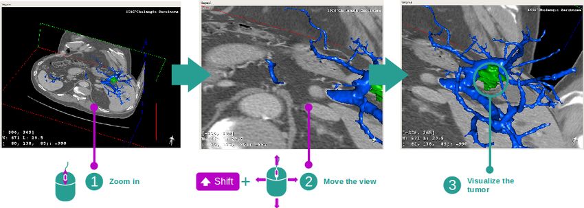
CHAPTER            1

                                                                                           Indications for use

Visible Patient Suite is medical imaging software that is intended to provide trained medical professionals with tools to
aid them in reading, interpreting, reporting, and treatment planning. Visible Patient Suite accepts DICOM compliant
medical images acquired from a variety of imaging devices, including CT, MR.
This product is not intended for use with or for the primary diagnostic interpretation of Mammography images.
The software provides several categories of tools. It includes basic imaging tools for general images, including 2D
viewing, volume rendering and 3D volume viewing, orthogonal Multi-Planar Reconstructions (MPR), image fusion,
surface rendering, measurements, reporting, storing, general image management and administration tools, etc.
It includes a basic image processing workflow and a custom UI to segment anatomical structures, which are visible in
the image data (bones, organs, vascular/airway structures, etc.), including interactive segmentation tools, basic image
filters, etc.
It also includes detection and labeling tools of organ segments (liver, lungs and kidneys), including path definition
through vascular/airway, approximation of vascular/airway territories from tubular structures and interactive labeling.
The software is designed to be used by trained professionals (including physicians, surgeons and technicians) and is
intended to assist the clinician who is solely responsible for making all final patient management decisions.

                                                                                                                       7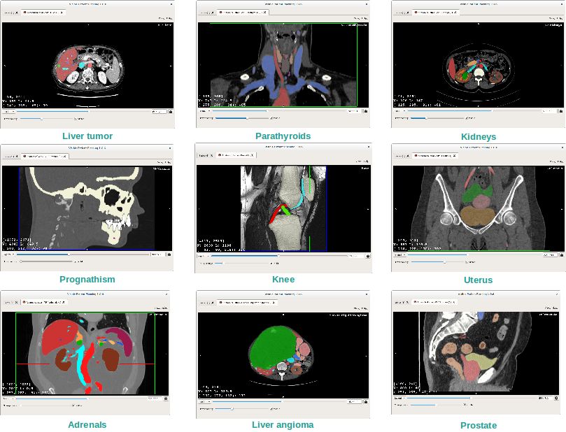
SDM-UM-VPSuite-Planning-1.0.12-en_v1 Visible Patient Planning

CHAPTER    2

              Contraindication

None known.

                             9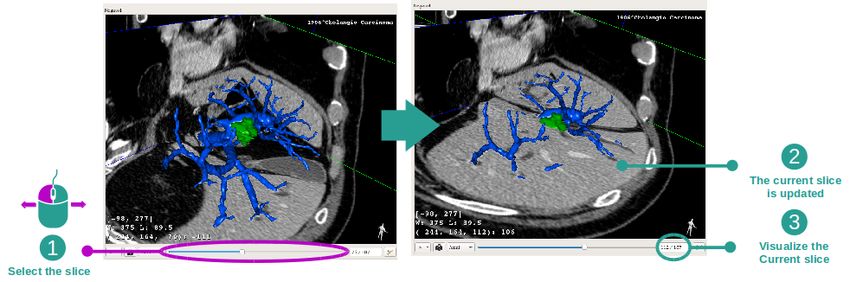
SDM-UM-VPSuite-Planning-1.0.12-en_v1 Visible Patient Planning
CHAPTER            3

                                                                                                           Cautions

3.1 General caution

This software is designed to be used by trained medical professionals and is intended to assist the clinician who is
solely responsible for making all final decisions.

3.2 Secure computing environment

Visible Patient requires the software to be installed on a secure workstation, compliant with FDA’s guidance about
cybersecurity. All images or resulting 3D models should be transferred via a user facility’s secured network file
transfer system.

3.3 Visible Patient data transfer

Visible Patient requires all transferred images to be anonymized and provided to and from the company via a user
facility’s secured network file transfer system. Visible Patient will not accept images in any other format or transferred
in any other manner.

3.4 3D model with transparency visualization caution

Several activities provide 3D model visualization with the possibility to use transparency. The rendering quality is
dependent on the computer’s hardware (especially the graphics card). If the computer does not comply with the
hardware requirements, there can be visualization approximations when 3D model transparency is enabled.
The following activities are concerned:
    • 3D model visualization
    • MPR3D visualization

                                                                                                                       11
SDM-UM-VPSuite-Planning-1.0.12-en_v1 Visible Patient Planning
• Clip applying activity
• Volume rendering activity
3.5 Volume rendering caution
The rendering quality and reliability depend on the computer’s hardware (especially the graphics card). If the computer
does not comply with the hardware requirements, there can be visualization approximations when merging volume
rendering and 3D model rendering with transparency.
3.6 Anatomical structures volumes caution
In Visible Patient suite, anatomical structure volumes are available through the organ manager and clip applying
activity. These volumes are computed from images. Consequently, the precision of these volumes depends on native
image quality (image voxel size).
For more information, please refer to Vascular and airways territories estimation.
3.7 Organ segments visualization caution
Organ segments visualization activity (Clip applying activity) is based on territories reconstruction, and segments are
deduced from an image. Consequently, organ segments are an approximation of the reality.
3.8 Distance measurement caution
The measurement tool manipulation requires extreme precision. While measuring a distance on a 3D image, both
contrast and level of zoom need to be precisely set otherwise measurement inaccuracy could happen. While measuring
a distance on a 3D model, level of zoom needs to be precisely set.CHAPTER 4
Technological Characteristics
4.1 System requirements and characteristics
Visible Patient Suite is designed to run on a standard standalone platform, through the installed operating system
(Windows or Mac). The hardware of such platform consists of an “off-the-shelf”, standard PC computer. Furthermore,
all software included in the suite (explained in detail below) can be installed on different computers and they are not
required to be interconnected through a network.
4.1.1 PC - Minimal System Requirements
• Operating System: Windows 7 x64
• Processor: Intel Core i3
• Video: Dedicated graphics card (since 2012)
• Memory: 4 GB RAM
• Storage: 10 GB available HD space
• Internet: Broadband Internet connection
• Media: Not required
• Resolution: 1024x768 or higher
4.1.2 PC - Recommended System Requirements
• Operating System: Windows 7 x64
• Processor: Intel Core i7 – 2.5 GHz
• Video: Nvidia GeForce GTX 760 or better
• Memory: 16 GB RAM
13SDM-UM-VPSuite-Planning-1.0.12-en_v1 Visible Patient Planning
• Storage: 300 GB available HD space
• Internet: Broadband Internet connection
• Media: Not required
• Resolution: 1920x1080 minimum display resolution
4.1.3 Mac - Minimal System Requirements
• Operating System: Mac OS 10.9 (Maverick) Any Apple computer released since 2010
• Video: Dedicated graphics card
4.1.4 Mac - Recommended System Requirements
• Operating System: Mac OS 10.9 (Maverick) Any Apple computer since late 2013 release
• Video: Dedicated graphics card
4.2 Software overview
4.2.1 Visible Patient Planning
Visible Patient Planning includes modules dedicated to data management and data analysis, and simply contains a
subset of the software modules present in Visible Patient Lab. This software offers a flexible visualization solution
to help trained medical professionals (usually clinicians) in the evaluation of patient’s anatomy and pathology to plan
therapy or surgery. This software provides a tool to load images and 3D models created with Visible Patient Lab. These
images and models can be displayed based on physician preferences using configurable viewing options or standard
protocols. Visible Patient Planning provides the clinician with a broad set of viewing and analysis tools to measure
and output selected image and models views.
4.3 Software modules
The modules of Visible Patient Suite can be grouped by categories:
Category Functionality Visible Patient Planning
Data management Image DICOM reader (MR/CT) X
Data management Visible Patient data reader/writer X
Image and surface analysis 2D image multi-planar representation (MPR) X
Image and surface analysis Image volume rendering X
Image and surface analysis Anatomical atlas X
Image and surface analysis 3D model visualization X
Image and surface analysis 3D model and image visualization X
Image and surface analysis Organ segments visualization X
The table above groups each software module into: data management, image and surface analysis and image and
surface processing. In addition, each individual software module is discussed in more detail below.SDM-UM-VPSuite-Planning-1.0.12-en_v1 Visible Patient Planning 4.3.1 Image DICOM reader (MR/CT) This module allows the software to read DICOM files and supports MR and CT modalities. The 3D data volume interpretation (2D DICOM slices merging) is automatic in this module. A DICOM series contains many 2D DICOM slices and these series slices can represent different data volume. To build each 3D data volume, slices need to be filtered, split and reordered. This DICOM reader uses each slice 3D position / orientation and slice acquisition time to split and reorder slices, as well to provide an automatic 3D data volume reconstruction. DICOM reader is used to read a DICOM folder, import 2D DICOM slices, and automatically interpret data to rebuild all 3D data volumes (3D images). 4.3.2 Manual DICOM parser (MR/CT) This more advanced module allows trained medical professionals to filter DICOM files manually to build the 3D data volume when the default reader fails. A DICOM series contains many 2D DICOM slices which can represent different data volumes. Again, to build each 3D data volumes, slices need to be filtered, split and reordered. This DICOM parser proposes different configurable filters, which work on DICOM tags. Trained medical professionals combine these filters to create 3D data volumes from DICOM images. 4.3.3 Visible Patient data reader/writer This module allows users to save and load data produced by Visible Patient Lab. This data contains images, 3D patient model, etc. This module also manages data backwards compatibility. Data are saved in a proprietary format on filesystem with a system to check: (1) the file integrity to secure transfer to another computer, and (2) the file version to manage software evolution and compatibility. Visible Patient data reader is used to read a Visible Patient Suite file. All data generated by Visible Patient Lab are stored in this file: 3D images, 3D models, anatomical atlases and organs segments. 4.3.4 2D image multi-planar representation (MPR) MPR corresponds to the most standard visualization technique developed and used on professional medical imaging workstations. The 2D MPR visualization activity allows one to visualize an image in different orientations, such as axial, frontal and sagittal. It also includes image windowing, change of the active image slice, translation, zoom- in/zoom-out, voxel information (coordinates and density), focus on a part of the image, distance computation, scene snapshot, etc. Image boundaries are shown by a colored square (red, blue or green) according to the current axis. 4.3.5 Image volume rendering The image volume rendering module corresponds to advanced visualization techniques developed and used on profes- sional medical imaging workstations: a 3D representation of the data volume. This module allows this visualization and includes a transfer function editor and several automated pre-computed transfer functions to propose different 3D renderings. 4.3.6 Anatomical atlas This module allows user to merge two planar image representations with transparency, and to visualize the result slice by slice. The first image is the CT/MR data, the second one is the patient anatomy atlas (a color image where each
SDM-UM-VPSuite-Planning-1.0.12-en_v1                                                           Visible Patient Planning

organ is represented). This activity allows one to check if the anatomical atlas is accurate and provides users a better
understanding of the patient’s anatomy.

4.3.7 3D model visualization

This module allows one to review the 3D patient model and its volume with classic 3D interactions, such as rotation,
translation, zoom-in/zoom-out. It is possible to manage organ visibility/ transparency to improve the visualization.

4.3.8 3D model and image visualization

This module allows the user to combine a 3D image MPR and a 3D model in the same view. All features described in
“2D image MPR” and “3D model visualization” are available here as well.

4.3.9 Organ segments visualization

This module allows one to review the 3D organ’s segments and their volume compared to the organ volume. As
outlined in the proposed indication for use, this module is only available for advanced lung/liver/kidney modeling.
The interaction is based on tubular structures to select vascular/airway segments.
CHAPTER           5

                                                                                 Installation instructions

5.1 Install Visible Patient Planning software

Visible Patient Planning installation can be started from an executable file.

5.1.1 How to install Visible Patient Planning on Windows

Start the installation

Double click the installation file provided by Visible Patient: the following installation welcome dialog will be dis-
played.

                                                                                                                   17
SDM-UM-VPSuite-Planning-1.0.12-en_v1 Visible Patient Planning Click “Next”. Accept the license License agreement is displayed.
SDM-UM-VPSuite-Planning-1.0.12-en_v1                                                        Visible Patient Planning

Read the license agreement and click “I agree” to continue the installation. (If you do not agree, click “Cancel” to
cancel the installation.)

Select the destination folder

The destination folder where the software will be installed is displayed.
SDM-UM-VPSuite-Planning-1.0.12-en_v1                                                    Visible Patient Planning

You can change this destination folder by clicking “Browse” and selecting a new destination folder. You can also
create a new one by clicking “Make New Folder”.
SDM-UM-VPSuite-Planning-1.0.12-en_v1                                                            Visible Patient Planning

Select your destination folder and click “Ok”.
To continue the installation, click “Next”.

Create a shortcut

You can then decide to create a shortcut for easier access to the software. By default, a shortcut will be created on your
computer desktop but you can choose another location. You can also enter a name to create a new start menu folder or
decide to not create a shortcut.

Finish the installation

To continue the installation, click “Install”.
The installation process starts.
SDM-UM-VPSuite-Planning-1.0.12-en_v1                                                            Visible Patient Planning

The installation takes a few seconds to proceed. When it is done, a message indicates that the installation is over. Click
“Finish” to close the setup window.
SDM-UM-VPSuite-Planning-1.0.12-en_v1                                                           Visible Patient Planning

Visible Patient Planning is now installed on your computer in the chosen destination folder.

Launch the software

You can start Visible Patient Planning by clicking the shortcut created during installation (by default on the computer
desktop).
If you encounter any issue with the software installation, please contact Visible Patient at support@visiblepatient.com.

5.1.2 How to install Visible Patient Planning on Mac

Start the installation

Double click the installation file provided by Visible Patient.
A license agreement window appears. Click “Agree” to continue the installation.

Install the application

Drag the Visible Patient Planning app into the application shortcut and drop it.
SDM-UM-VPSuite-Planning-1.0.12-en_v1                                                           Visible Patient Planning

Visible Patient Planning is now installed.

Launch the software

Visible Patient Planning can be started from the application folder by double clicking the Visible Patient Planning
icon.
If you encounter any issue with the software installation, please contact Visible Patient at support@visiblepatient.com.
CHAPTER            6

                                                                                       Operating instructions

6.1 How to load data

Each software feature is called an “activity”. Each activity is displayed in a dedicated tab of the application’s main
window. The series activity is the main one and it is always available. From this activity, other activities can be started.
In Visible Patient Suite, two types of data can be loaded:
    • VPZ data provided by Visible Patient
    • DICOM data containing a CT or MR series.

                                                                                                                         25
SDM-UM-VPSuite-Planning-1.0.12-en_v1 Visible Patient Planning
Data is divided into series which can be visualized using the different available activities.
Four types of series are available:
• Image series (a medical image)
• Model series (a set of 3D reconstructions)
• Anatomical Atlas series
• Clip Applying series
Those series can then be opened in the following activities:
• 2D MPR activity, opened with an image series
• 3D MPR activity, opened with an image series and a model series
• Volume rendering activity, opened with an image series and an optional model series
• 3D Model activity, opened with an image series
• Anatomical atlas activity, opened with an anatomical atlas series
• Dicom reader activity, no input data required
• Sender activity, no input data required
In order to load a VPZ file, click “Open” and select “VPZ File”. In the file selector, select a VPZ file on your computer
and click “Open”.SDM-UM-VPSuite-Planning-1.0.12-en_v1 Visible Patient Planning The principle is the same to load DICOM data.
SDM-UM-VPSuite-Planning-1.0.12-en_v1                                                         Visible Patient Planning

Click “Open” and select “DICOM Reader”. In the file selector, select a folder containing DICOM files and click
“Choose”.

6.2 How to visualize an image

The 2D MPR activity is dedicated to medical image visualization, particularly anatomical structures. This can be
performed in four easy steps. This activity will be introduced by presenting a liver tumor visualization.
It includes functionalities such as anatomical structures measurement and snapshots of the view.
SDM-UM-VPSuite-Planning-1.0.12-en_v1                                                            Visible Patient Planning

6.2.1 Prerequisites

In order to start the 2D MPR activity, select an image series in the Series activity (How to load data) and click “Launch
activity”. Select “2D MPR” and click “OK”.

6.2.2 Visualize the patient’s anatomy

Let’s get started with a short description of the activity layout.
SDM-UM-VPSuite-Planning-1.0.12-en_v1                                                           Visible Patient Planning

This activity is composed of three views, a main one (left view) representing an axial view of the image and two
secondary views representing sagittal and frontal views.
As an example, the following steps will be based on the analysis of a patient’s liver tumor.

Step 1 : Navigate through slices to localize an anatomical part

Below the axial view, move the slider to navigate through image slices and localize the tumor inside the liver. To use
the slider click on it and move the mouse.
SDM-UM-VPSuite-Planning-1.0.12-en_v1                                                         Visible Patient Planning

Step 2 : Adjust window level

Once the tumor is localized, the window level can be changed by holding right mouse button and moving the cursor
on the image.

Step 3 : Focus the anatomical part

Use the middle mouse button to focus the liver tumor. When clicked, all three views focus on the clicked point.
SDM-UM-VPSuite-Planning-1.0.12-en_v1                                                         Visible Patient Planning

Step 4 : Detail the anatomical area

Finally, you can improve tumor visualization while rolling the mouse wheel to zoom in/out and use the shift key + left
mouse click combination to move the image.

6.2.3 Examples of other anatomical structures

The previously detailed scenario can be applied to other anatomical structures using the 2D MPR activity. The follow-
ing section lists several examples of structures that can be visualized. This list is not exhaustive.
SDM-UM-VPSuite-Planning-1.0.12-en_v1                                    Visible Patient Planning

6.2.4 Additional information

Additional image information

On the 2D MPR view there is a lot of complementary image information.
SDM-UM-VPSuite-Planning-1.0.12-en_v1                                                      Visible Patient Planning

  1. Patient name
  2. Position marker (this information is also displayed at upper, left, lower and right border of the view)
            • S : Superior / I : Inferior
            • A : Anterior / P : Posterior
            • R : Right / L : Left
  3. Image information (advanced information, medical image analysis knowledge required)
            • On the first line, bounds of current image window range
            • Next, width of current image window followed by current window level
            • On a third line are shown coordinates and value of last picked pixel (using mouse middle click on the
              image).
SDM-UM-VPSuite-Planning-1.0.12-en_v1 Visible Patient Planning Take a measurement Anatomical structures can be measured using the distance tools. To do so, first click “Add distance”, then move distance with the handles. You can hide the displayed distance: And also remove distance:
SDM-UM-VPSuite-Planning-1.0.12-en_v1                                                       Visible Patient Planning

Change main view image orientation

Main view orientation can be switched by selecting the desired orientation in the dedicated menu. When the main
view orientation is changed, the other views adapt their orientation in order to display all axes at the same time.
SDM-UM-VPSuite-Planning-1.0.12-en_v1                                      Visible Patient Planning

Save a snapshot

In order to save the current view as an image, use the snapshot button.
SDM-UM-VPSuite-Planning-1.0.12-en_v1                                                            Visible Patient Planning

Get physical value of a voxel

A left mouse click on the image displays the voxel coordinates and value of the voxel under mouse cursor. The unit of
this value depends on the image type.

6.3 How to visualize a 3D model

The main purpose of the 3D model activity is to the visualize and interact with your 3D model.

6.3.1 Prerequisites

In order to start a 3D Model activity, a model series is required. Select it from Series activity (How to load data) and
click “Launch activity”, or double click the series.

6.3.2 Visualize the patient’s anatomy

Let’s get familiar with the activity layout. There is one main view in the 3D model activity.
SDM-UM-VPSuite-Planning-1.0.12-en_v1                                                        Visible Patient Planning

In this 3D view, and thanks to the organ manager, you can perform several interactions with your model.
SDM-UM-VPSuite-Planning-1.0.12-en_v1                                                           Visible Patient Planning

The organ manager lists all organs present in the 3D model. It allows to hide/show organs of the model and to change
their appearance by modifying their color or opacity. The organ manager also gives information about organ volumes.
As an example, the following steps will be based on the analysis of a patient’s liver tumor.
SDM-UM-VPSuite-Planning-1.0.12-en_v1                                                         Visible Patient Planning

Step 1 : Hide organs to visualize an anatomical part

Some organs may obstruct the visualization of anatomical parts. Per the organ manager, these organs can be hidden.
To do so, open the organ manager and uncheck the organ you want to hide. You can then display it again by checking
back the organ’s visibility box.

Step 2 : Modify an organ opacity

You may also want to visualize the inner part of an organ. The organ manager allows you to modify the opacity of an
organ.
To do so, open the organ manager, select the desired organ and modify the opacity with the slider underneath the organ
manager.
SDM-UM-VPSuite-Planning-1.0.12-en_v1                                                        Visible Patient Planning

Step 3 : Detail the anatomical area

The 3D model activity allows you to interact with your model.
You can rotate your model by clicking and holding the left mouse button while dragging the cursor.

You can zoom in or out by using the mouse wheel.

Finally, you can shift your model by clicking and holding the middle mouse button while dragging the cursor.
SDM-UM-VPSuite-Planning-1.0.12-en_v1                                                         Visible Patient Planning

6.3.3 Examples of other anatomical structures

The previously detailed scenario can be applied to other anatomical structures using the Model activity. The following
section lists several examples of structures that can be visualized. This list is not exhaustive.
SDM-UM-VPSuite-Planning-1.0.12-en_v1                                                       Visible Patient Planning

6.3.4 Additional information

Additional image information

The Model activity displays the patient’s name and an orientation marker on the 3D view.
SDM-UM-VPSuite-Planning-1.0.12-en_v1 Visible Patient Planning
SDM-UM-VPSuite-Planning-1.0.12-en_v1                                                        Visible Patient Planning

Reset the view

At any moment, you can reset the view using one of the three reset button located above the main view. These buttons
reset the view to axial, frontal or sagittal view.

Save a snapshot

If you want to save the current view as an image, use the snapshot button.
SDM-UM-VPSuite-Planning-1.0.12-en_v1                                                           Visible Patient Planning

6.4 How to visualize an image with a model

The 3D MPR activity is dedicated to the visualization of medical images and 3D models. The main purpose of this
activity is to visualize your 3D models with their corresponding medical images.
This activity includes functionalities such as measurements of anatomical structures and saving snapshots.

6.4.1 Prerequisites

In order to start a 3D MPR activity, an image series and its associated model series are required. Typically, these data
are loaded from a VPZ file.
Select both series from Series activity (How to load data) by holding the Ctrl key pressed during the series selection.
Click “Launch activity”, select “3D MPR” and click “Ok”.

6.4.2 Visualize the patient’s anatomy

The 3D MPR activity layout is composed of three views.
SDM-UM-VPSuite-Planning-1.0.12-en_v1                                                           Visible Patient Planning

The main view displays your 3D model and the associated image. The two other views display the frontal and sagittal
views of the image.
As an example, the following steps will be based on the analysis of a patient’s liver tumor.

Step 1 : Hide organs to visualize an anatomical part

In order to visualize the tumor located inside the liver, you can hide the unwanted organs. To do so, click on the organ
manager button and unselect the organs that must be hidden.
For more detail on how the organ manager works, please refer tor the 3D model activity documentation.
SDM-UM-VPSuite-Planning-1.0.12-en_v1                                                      Visible Patient Planning

Step 2 : Rotate the model to get a global visualization

In order to rotate your 3D model, click and hold the left mouse button on the main view and move the cursor. The
model and the image will rotate accordingly.

Step 3 : Detail the anatomical area

Use the mouse wheel to zoom in or out. You can shift the view by pressing and holding the Shift key, while holding
the middle mouse button and dragging the mouse on the view.
SDM-UM-VPSuite-Planning-1.0.12-en_v1                                                           Visible Patient Planning

Step 4 : Update the current slice

Use the slider under the main view to change the current slice. The slice corresponding to the selected orientation will
be updated accordingly.

Step 5 : Measure an anatomical part

Use the add distance button to place a new measure on the view. Once created, the distance can be moved by clicking
and holding the left mouse button on one of the two handles located at the extremity of the segment.

6.4.3 Examples of other anatomical structures

The previously detailed scenario can be applied to other anatomical structures using the 3D MPR activity. The follow-
ing section lists several examples of structures that can be visualized. This list is not exhaustive.
SDM-UM-VPSuite-Planning-1.0.12-en_v1                                    Visible Patient Planning

6.4.4 Additional information

Additional image information

On the 3D MPR view there is a lot of complementary image information.
SDM-UM-VPSuite-Planning-1.0.12-en_v1                                                       Visible Patient Planning

   1. Patient name
   2. Orientation marker
   3. Image information (advanced information, medical image analysis knowledge required)
         • On the first line, bounds of current image window range
         • Next, width of current image window followed by current window level
         • On a third line, coordinates and value of last picked voxel.

Adjust window level

You can change the window level by right clicking and holding the button while moving the cursor.
SDM-UM-VPSuite-Planning-1.0.12-en_v1 Visible Patient Planning Focus an anatomical part Use the middle mouse button to focus an anatomical part. When picking a point on one view, all three image planes (axial, frontal, sagittal) will intersect on that point. Reset the view
SDM-UM-VPSuite-Planning-1.0.12-en_v1                                                        Visible Patient Planning

At any moment, you can reset the view using one of the three reset button located above the main view. Those buttons
reset the view to the axial, frontal or sagittal view.

Select image orientation

The orientation mode can be selected using the dedicated menu located under the main view. Once the orientation is
changed, the slider updates the corresponding view when moved.

Select number of image planes

The number of displayed image planes can be changed using the selector located under the main view. Three modes
are available :
    • No slices removes all image planes
    • One slice only displays the plane of the selected axis
    • Three slices displays all three planes
SDM-UM-VPSuite-Planning-1.0.12-en_v1 Visible Patient Planning Save a snapshot In order to save the current view as an image, use the snapshot button. Measurement in side views To get an explanation on how to perform a measurement on a 2D medical image, please refer tor the 2D MPR activity documentation at section Take a measurement. 6.5 How to visualize a volume The Volume rendering activity is dedicated to the visualization of the medical image as a volume rendering. The activity allows to integrate the associated 3D model into the volume rendering for a better understanding of the patient anatomy. This activity includes a transfer function manager which allows to change the display of the volume rendering accord- ing to the anatomical parts you want to visualize. 6.5.1 Prerequisites In order to start a Volume Rendering activity, an image series is required. Optionally, its corresponding model series can be associated. Select the series in Series activity (How to load data), click “Launch activity”, select “Volume Rendering” and click “Ok”. 6.5.2 Visualize the patient’s anatomy Let’s get started with a short description of the activity layout.
SDM-UM-VPSuite-Planning-1.0.12-en_v1                                                           Visible Patient Planning

This activity is composed of two views. The main one on the left displays the volume rendering of your image. The
view on the right is composed of two tabs. The first one displays an axial view of your image. The second one is a
transfer function editor.
As an example, the following steps will be based on the analysis of a patient’s liver tumor.

Step 1 : Hide the 3D model
SDM-UM-VPSuite-Planning-1.0.12-en_v1                                                         Visible Patient Planning

If the activity has been launched with an image and a model, you might want to hide the model in order to see only
the volume rendering. To do so, uncheck the “Show Mesh” button.

Step 2 : Select a transfer function

You can change the volume rendering tranfer function in order to display other anatomical parts. The transfer function
establish a correspondance between pixel values and colors in order to highlight specific information. To change the
tranfer function, click on the transfer function selector and select the one you need.

Step 3 : Adjust the window level

The volume rendering can be adjusted by changing the window level of the medical image. This can be perfomed
exactly as in the 2D MPR activity (Step 2 : Adjust window level).
SDM-UM-VPSuite-Planning-1.0.12-en_v1                                                           Visible Patient Planning

Step 4 : Display a 3D model into the volume rendering

As in step 1, you can display 3D models by clicking on the “Show Mesh” button. The organ manager is available in
this activity. Thus, you can change opacity and color of the organs models like in the 3D model activity. For the next
steps, we will be displaying the patient’s liver tumor in the volume view.

Step 5 : Detail an anatomical area

The volume rendering interactions are the same as the interactions in the 3D model activity.

Step 6 : Use the 3D slice cursor

In order to localize a point in the volume rendering view, you can use the 3D slice cursor available in “View” menu:
    • click “Show 3D slice cursor”
    • click “Configure 3D slice cursor”.
SDM-UM-VPSuite-Planning-1.0.12-en_v1 Visible Patient Planning Then, you just have to pick a point on the right side view using the middle mouse button. The related point will be displayed in the volume rendering view using a white sphere. On the image above, the cursor is moved on top of the patient’s liver tumor. The negato interactions are the same as in the 2D MPR activity. Step 7 : Update the cropping box The visualization of the volume can be imroved by using the cropping box. To use it, click “Show/Hide box cropping”. It can then be moved or resized by clicking and dragging one of the handle at the side of the box. The volume will be cropped accordingly. You can reset the box by clicking “Reset box cropping”. 6.5.3 Examples of other anatomical structures The previously detailed scenario can be applied to other anatomical structures using the Volume Rendering activity. The following section lists several examples of structures that can be visualized. This list is not exhaustive.
SDM-UM-VPSuite-Planning-1.0.12-en_v1                                                        Visible Patient Planning

6.5.4 Additional information

Additional image information

The volume rendering view displays an orientation marker and the patient’s name, just as in the 3D model activity.
SDM-UM-VPSuite-Planning-1.0.12-en_v1                                                           Visible Patient Planning

Transfer function editor

The transfer function manager allows one to create, reset, rename, delete, save and load transfer functions. Per the
transfer function editor, you can customize your functions by plotting colored points on your image’s histogram.

Save a snapshot

Snapshots of the volume rendering view can be done using the snapshot button, just as in any other activity.

Change 2D negato orientation

To get an explanation on how the cross displaying system works, please refer to the MPR2D activity documentation
(see Change main view image orientation).

6.6 How to use the Anatomical Atlas Activity

The Anatomical Atlas activity is dedicated to the visualization of segmented anatomical parts thanks to colored image
areas called atlas.

6.6.1 Prerequisites

In order to start an Anatomical Atlas activity, an anatomical atlas series is required. Typically, these data are loaded
from a VPZ file. Select the series from Series activity (How to load data) and click “Launch activity”, or double click
the series.
SDM-UM-VPSuite-Planning-1.0.12-en_v1                                                       Visible Patient Planning

6.6.2 Visualize the patient’s anatomy

The activity includes an image view allowing one to localize segmented anatomical parts per colored image areas.
As an example, the following steps are based on the analysis of a patient’s lung tumor.

Step 1 : Update the anatomical atlas transparency
SDM-UM-VPSuite-Planning-1.0.12-en_v1                                                          Visible Patient Planning

The Anatomical Atlas activity allows one to change the atlas transparency to enhance the understanding of the different
anatomical parts. To do so, use the transparency slider located under the image view. The atlas can also be hidden by
unchecking the visibility box next to the transparency slider.

Step 2 : Localize an anatomical part

In order to localize a specific anatomical part, use the slider located over the transparency slider. Once the slice is
selected, the transparency can be updated to improve the visualization of the tumor.

6.6.3 Examples of other anatomical structures

The previously detailed scenario can be applied to other anatomical structures using the Anatomical Atlas activity.
The following section lists several examples of structures that can be visualized. This list is not exhaustive.
SDM-UM-VPSuite-Planning-1.0.12-en_v1                                                           Visible Patient Planning

6.6.4 Additional information

Additional image information

As in the 2D MPR activity, image information is displayed on the view.
   1. Patient name
   2. Position marker (this information is also displayed at upper, left, lower and right borders of the view)
         • S : Superior / I : Inferior
         • A : Anterior / P : Posterior
         • R : Right / L : Left
   3. Image information (advanced information, medical image analysis knowledge required)
         • On the first line, bounds of current image window range
         • Next, width of current image window followed by current window level
         • On a third line, coordinates and value of last picked voxel.
SDM-UM-VPSuite-Planning-1.0.12-en_v1 Visible Patient Planning Adjust window level As in the other activities including a 2D negato, window level can be changed by right clicking and holding the button while moving the cursor. Only the image window level is impacted, the atlas display remains unchanged. Select the orientation mode As in the other activities including a 2D negato, the orientation mode can be selected using the selector located under the main view. Once the orientation mode has been set, the slider updates the corresponding view when moved. Save a snapshot In order to save the current view as an image, use the snapshot button, as in other activities. 6.7 How to visualize organ segments The Clip Applying activity is dedicated to the visualization of organs segments (Please note that organ segments are approximated). Clips can be placed on the organ’s network in order to display the different segments and approxima- tions of the computed volumes. 6.7.1 Prerequisites In order to start a Clip Applying activity, a clip applying series is required. Typically, these data are loaded from a VPZ file. Select the series from Series activity (How to load data) and click “Launch activity”, or double click the series.
SDM-UM-VPSuite-Planning-1.0.12-en_v1                                                           Visible Patient Planning

6.7.2 Apply clips on an organ’s network

The activity includes a 3D view allowing one to visualize the organs segments.

Step 1 : Hide organs to visualize an anatomical part

The first step is to hide anatomical parts that obstruct the tumor visualization with the organ manager.
For more information about the organ manager, please refer to the 3D model activity documentation.
SDM-UM-VPSuite-Planning-1.0.12-en_v1                                                         Visible Patient Planning

Step 2 : Detail the anatomical area

In the main view, the same interactions as in the 3D model activity (rotation, zoom and translation) can be performed.

Step 3 : Clip applying simulation

To show a segment corresponding to a network section, right click on the corresponding section. To hide a segment,
simply right click on it. Approximated volumes of several organ parts, such as resected part, remaining part, and
remaining healthy part are computed accordingly.

Volumes approximation method

Simulated resected part:
      Volume of simulated resected part = volume of all displayed segments
      Percentage of simulated resected part = volume of simulated resected part / targeted organ volume
Simulated remaining part:
      Volume of simulated remaining part = targeted organ volume – volume of simulated resected part
      Percentage of simulated remaining part = volume of simulated remaining part / targeted organ volume
Targeted organ nodules:
      Volume of targeted organ nodules = sum of nodule volumes located inside the targeted organ
      Nodules : mass or lump detected inside the targeted organ and present in the 3D modeling
Healthy organ:
SDM-UM-VPSuite-Planning-1.0.12-en_v1 Visible Patient Planning
Healthy organ volume = targeted organ volume - volume of targeted organ nodules
Simulated remaining healthy part:
Volume of simulated remaining healthy part = remaining organ volume - remaining nodules volume
Percentage of simulated remaining healthy part = volume of simulated remaining healthy part / healthy
organ volume
6.7.3 Examples of other anatomical structures
The previously detailed scenario can be applied to other anatomical structures. Clip applying can also be used to
visualize lungs and kidneys segments.
6.7.4 Additional information
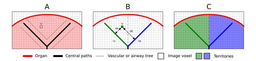
Vascular and airways territories estimation
Vascular and airways territories proposed in this activity are an approximation of the real patient anatomy. The method
used to estimate these territories is based on the organ vasculature or the organ airway tree and the method accuracy
directly depends on the tree segmentation quality. Territories estimation is the result of the following process.
First, the vascular or airway tree segmentation is used to compute tubular central paths (A). Then these central paths,
who represent the tubular structure, are labeled by trained medical professionals to associate each path to an organ
territory . Then, for each image voxel of the targeted anatomical structure, the method finds the closest central path
and associate the same organ territory (B). Finally, the labeled image result is meshed to obtain all territories estimation
(C).SDM-UM-VPSuite-Planning-1.0.12-en_v1 Visible Patient Planning The method accuracy directly depends on the tree segmentation quality. Image resolution, contrast product diffusion inside the organ vascular system during the image acquisition, etc, may have an impact on the territories estimation. Additional image information As in the 3D model activity, the patient’s name and an orientation marker is displayed on the view. Save a snapshot In order to save the current view as an image, use the snapshot button.
SDM-UM-VPSuite-Planning-1.0.12-en_v1 Visible Patient Planning
CHAPTER            7

                                                                                                  Maintenance

No maintenance is required for Visible Patient Suite. To control software distribution, a license system is used in each
software of Visible Patient Suite.

7.1 Planning

Planning software comes with integrated license which are granted for 6 months.

7.2 License update

60 days before license expiration, a popup with information about expiration date appears each a software is started.
It is recommended to check for a new software version if the expiration date is less than 30 days away. If there is no
new version, please contact the support for a new license.

                                                                                                                     71
SDM-UM-VPSuite-Planning-1.0.12-en_v1 Visible Patient Planning
CHAPTER          8

                                                                                        Troubleshooting

8.1 General troubleshooting

8.1.1 I can’t open my DICOM file

DICOM is a standard for medical data. This standard implementation varies from one company to an other. If the
software can’t read your DICOM files, more information is available at the end of the DICOM reading process. When
the process is over, a popup appears. Click “Details” to see additionnal information:

                                                                                                              73
SDM-UM-VPSuite-Planning-1.0.12-en_v1 Visible Patient Planning
You can see several messages which are classified this way:
Icon Signification Consequence
Information Information about reading process
Warning Information that can induce wrong reading
Critical Critical error, the series is not read at all
Should you encounter any problems with DICOM reading, please contact Visible Patient support.
8.2 Organ’s segments visualization troubleshooting
8.2.1 I don’t see any volume displayed
If this message is displayed in the upper left corner:SDM-UM-VPSuite-Planning-1.0.12-en_v1 Visible Patient Planning Note: Incoherence detected during volume computation The system has detected an incoherence in volume computation. Consequently, the system displays this message to warn you about a problem with the computation of segment volumes. This message is a risk control measure. Please contact Visible Patient support if you encounter this problem. 8.2.2 I see a warning about simulated vascular territories in Clip Applying activity When the Clip Applying activity (Organ’s segments visualization) is started, this message is displayed in red: Note: Simulated Vascular Territories are computed from the selected network. The precision is then fully dependent of the native image quality. This message is expected and is a reminder about the organ’s segments computation and the fact that this modeling depends on native image quality. So the proposed segments are an approximation of the reality.
You can also read