MULTIBODY ANALYSIS OF THE DESMODROMIC VALVE TRAIN OF THE DUCATI MOTOGP ENGINE
←
→
Page content transcription
If your browser does not render page correctly, please read the page content below

MULTIBODY DYNAMICS 2007, ECCOMAS Thematic Conference
                                                                     C.L. Bottasso, P. Masarati, L. Trainelli (eds.)
                                                                                  Milano, Italy, 25–28 June 2007

MULTIBODY ANALYSIS OF THE DESMODROMIC VALVE TRAIN OF
             THE DUCATI MOTOGP ENGINE

      David Moreno? , Emiliano Mucchi† , Giorgio Dalpiaz† , and Alessandro Rivola‡
                       ? Departamentode Ingenieria de Sistemas Industriales
 Universidad Miguel Hernández, Campus de Elche, Avda. de la Universidad s/n, 03202 Elche, Spain
                                  e-mail: dmoreno@umh.es

                                   † Department   of Engineering
                      University of Ferrara, Via Saragat 1, 44100 Ferrara, Italy
          e-mails: emiliano.mucchi@unife.it, giorgio.dalpiaz@unife.it

                                             ‡ DIEM
                University of Bologna, Viale Risorgimento 2, 40136 Bologna, Italy
                          e-mail: alessandro.rivola@unibo.it

Keywords: Desmodromic valve train, Motorcycle, Experimental validation.

Abstract. This paper presents a preliminary study concerning a multibody model of the des-
modromic valve train used in the Ducati MotoGP engines. The desmodromic mechanism has
a positive cam that causes the dynamic effects to be partly different from common valve trains,
where the valve spring plays an important role. The presented model includes only one cam-
valve mechanism. In a further step of the research, it will be possible to develop and expand the
model by introducing the other cam-valve mechanisms and other mechanical parts that com-
pose the system in order to obtain a complete model of the valve train. In the first part of this
work, the generation of the cam profiles is explained. The second part is focused on the descrip-
tion of the multibody model employed for the dynamic simulations. Finally, the experimental
validation is presented and discussed. The comparison between the numerical results and the
experimental data is encouraging even if it shows that the effectiveness of the model is not com-
pletely achieved. Therefore, it will be necessary to improve the model by including the presence
of other mechanical parts of the valvetrain, as well as other important dynamic effects as, for
example, the link flexibility.

                                                  1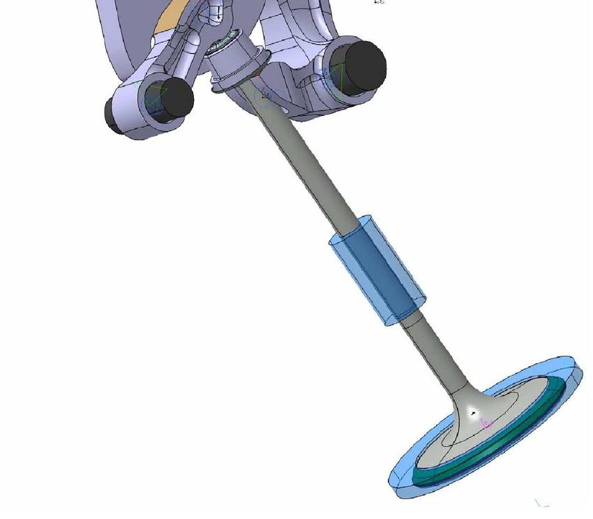
David Moreno, Emiliano Mucchi, Giorgio Dalpiaz and Alessandro Rivola

1   INTRODUCTION
   When a mechanism operates at a high speed, its dynamic behaviour is deeply affected by
link elastic flexibility and mass distribution, as well as the effects of backlash and friction in
joints. As a consequence, motion alterations may occur, causing mechanisms to fail in the
proper execution of their tasks. High accelerations and dynamic stress levels may also produce
early fatigue failures, and high levels of vibration and noise may arise. In the particular field
of valve trains for high-performance engines, these dynamic effects are particularly important
since they may cause serious functional troubles, such as jump and bounce phenomena.
   Thus, increasing attention is addressed to the elastodynamic analysis in order to predict
the dynamic behaviour, forces and impacts, and to identify the causes of failures and poor
performances. However, the papers on this topic generally concerns widely-used trains with
closing springs. In this case, the valve spring plays an important role in the system dynamics
and its accurate modelling is required. On the other hand, in the case of desmodromic valve
trains (mechanisms with positive-drive cams) the dynamic effects are partly different, as studied
in [1] and [2].

                                                                                           C o n ju g a te
                                                                                                c a m

                                                                                                   P o s itiv e
                                                                                                     ro c k e r

                                                              A d ju s te r                 N e g a tiv e
                                                                                              ro c k e r

                                                                  V a lv e
                                                                   s e a t

                                                                              V a lv e - h e a d

Figure 1: (a) General view of the desmodromic valve train of Ducati motorbike engines with four valves per
cylinder; (b) schematic of the cam mechanism driving a single valve.

    Some of the authors have already developed non-linear lumped-parameter models of the des-
modromic valve train, Ref. [1] and [2]. The aim of this paper is to present a different modelling
approach based on a multibody code, namely LMS Virtual.Lab Motion [3], integrated with
user defined procedures implemented in Matlab and FORTRAN.
    An integrated multibody-FEM model, will make it possible to study the dynamic behaviour
of the timing system, considering the elasticity of the bodies and evaluating the stress, strain and
vibrational states of the components under different operating conditions in a more accurate
way. Attention will be addressed to the benefits and drawbacks of multibody approach with
respect to lumped parameter models.

2   DESCRIPTION OF THE DESMODROMIC VALVE TRAIN
   This work concerns the timing system of the fourcylinder ’L’ engine of Ducati racing mo-
torbikes, having double overhead camshafts, desmodromic valve trains and four valves per

                                                    2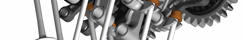
David Moreno, Emiliano Mucchi, Giorgio Dalpiaz and Alessandro Rivola

cylinder. This system is partially shown in the general view of Fig. 1(a): two camshafts with
four conjugate cams each one are driven by a gear transmission; one camshaft drives the four
intake valves and the other one the four exhaust valves.
    The schematic of the cam mechanism driving a single valve is shown in Fig. 1(b): the lobes
of a conjugate cam are in contact with their respective rockers; these two rockers are then in
contact with the adjuster located at the tip of the valve. Thus, it is possible to identify two parts
of the mechanism, each one consisting of one cam lobe and its corresponding rocker. They give
valve acceleration in positive and negative directions respectively, where the positive direction
is considered to be the direction of the opening valve. Here the terms ’positive’ and ’negative’
cam disc/rocker are used; however, these links are commonly, but improperly, called ‘opening’
and ‘closing’ cam disc/rocker, respectively.
    With respect to the more widely-used trains with closing springs, the desmodromic trains
make it possible to give higher valve accelerations, preventing the follower from jumping off
the cam, without employing a very stiff closing spring; on the other hand, the mechanical com-
plexity of the desmodromic system is justified only in high-speed engines with single-cylinder
heads, such as Ducati engines.

3   GENERATION OF THE DESMODROMIC CAM PROFILES
    This section is intended to describe the cam synthesis process, i.e. starting from the valve
displacement law (Fig. 2 left) and taking into account the geometry of the mechanism, the pro-
files of both cams will be obtained (Fig. 2 right). It is worth noting that, in order to control the
backslash as a function of the camshaft angle, each subsystem (positive and negative) was cre-
ated following a different motion law. Both are shown in Fig. 2; red for the positive subsystem
and blue for the negative one.

                                                                                                              90
                                           1                                                        120                60
        Valve displacement [normalized]

                                          0.8
                                                                                             150                            30

                                          0.6

                                          0.4
                                                                                           180                                    0

                                          0.2
                                                                                             210                            330
                                           0

                                                0      100         200          300                 240               300
                                                         Camshaft angle [deg]                                270

Figure 2: Cam generation process. Both cam profiles (positive and negative) are generated starting from the
displacement laws shown in the graph on the left.

   In order to tackle the generation problem, a specific multibody model is created. The cam
synthesis is clearly a kinematic case. Therefore, the backslashes of the different links that
compose the mechanism are not considered and a set of ideal constrains is used. The schematic
of the model is depicted in Figure 3.

                                                                                      3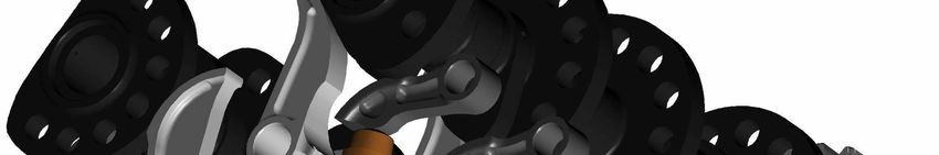
David Moreno, Emiliano Mucchi, Giorgio Dalpiaz and Alessandro Rivola

                     Figure 3: Multibody model employed for the CAM generation.

    As it is shown, the model inputs (depicted as joint drivers) are the imposed motion of the
valve and the camshaft angle. The kinematic chain that links these inputs with the output,
i.e. the profile of the CAM, consist of four bodies and 5 kinematic constrains. Although the
structure of this chain is always the same, the bodies that compose it depend on the conjugate
CAM to be generated. For each CAM, positive or negative, their corresponding rocker and
adjuster are used.
    The active adjuster is bracketed to the valve through a bracket joint that constrains all the
DOFs between both bodies. The valve is also linked to ground by means of a translational
joint, which is driven so that the valve follows the desired displacement. The motion is then
transmitted to the active rocker through a curve-to-curve joint. This kinematical joint defines a
bilateral contact constraint between two curves, one on each body, in order to keep the tangent
vectors parallel at the contact point. Slip is also allowed.
    The CAM body consists only of an axis system, which is used to reference the points that
compose the profile of the CAM. A driven revolute joint is used in order to attach this body
to ground. It is worth noting that the camshaft angle was properly synchronized with valve
displacement.
    Finally, in order to relate the motion of the rocker with the CAM body, a specific tool from
the Virtual.Lab Engine Library is used. It is called CAM Generator and allows to create a CAM
profile by taking as input the motion of the follower and other parameters like the dwell radius

                                                 4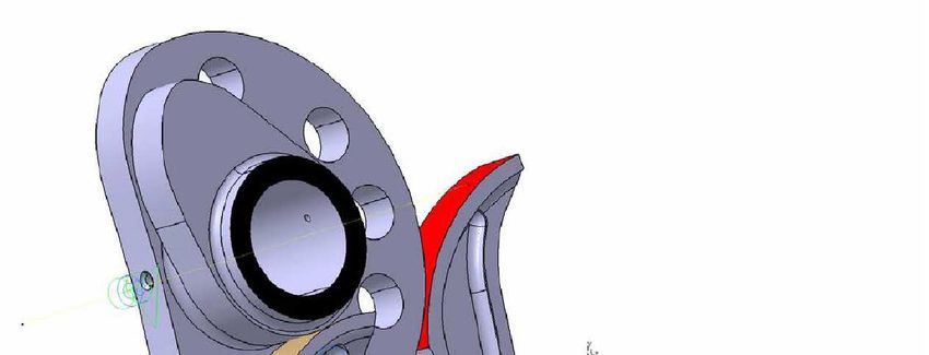
David Moreno, Emiliano Mucchi, Giorgio Dalpiaz and Alessandro Rivola

and the number of points of the profile. The result is a file containing the profile points.
    By means of the described model, the positive and negative cams were generated. This pro-
files will be used in the following sections to carry out dynamic simulations of the desmodromic
system.

4     DYNAMIC SIMULATION
4.1    General description of the dynamic model
    This section describes the multibody model of the desmodromic valve train, which is being
developed using LMS Virtual.Lab Motion. At this stage, only a single valve sub-system has
been modelled in order to simplify the estimation of the model parameters. Figure 4 shows the
schematic of this model, composed of eight rigid bodies and twelve massless parts. The latter,
also called dummy bodies, will be used in a forthcoming flexible model as an interface to allow
meshed parts to interact with the rest of the multibody model.
    The transmission that drives the camshaft has been neglected in order to focus the modelling
process on the valve mechanism. Because of this, the model input is the angular speed of the
camshaft, which is depicted in the schematic as Joint Driver. This input drives the revolute joint
that links the camshaft with the dummy camshaft. Unlike the rest of the dummy bodies, which
will be ignored for now, this one has a key role in the rigid model. It is introduced to be able
to consider the camshaft bending compliance at the point where the CAM is placed. To do
so, a linear bushing (i.e. a 6 DOF spring-damper) and a planar joint, both acting between the
ground and the dummy body, are employed to model the camshaft stiffness in the XY plane.
The driven revolute joint, on the other hand, constrains the relative angular motion between the
dummy camshaft and the camshaft. Otherwise, if both elements were applied on the camshaft,
the revolute joint would cancel the effect of the bushing.
    As shown in the schematic, both the positive and the negative rocker are related to the
camshaft by means of specific CAM contact elements taken from the Virtual.Lab Motion En-
gine library. Therefore, the cam surface is modelled using a 5th order spline. For each cam in
the simulation, this spline is used to determine the penetration depth, velocity and sliding ve-
locity between the cam and the follower. These parameters are then used to generate the forces
in the contact according to the following expressions:

                         FN (xp ) = k1 xp + k2 x2p + cp ẋp   (penetration)                       (1)

                         FN (xp ) = k1 xp + k2 x2p + cs ẋp   (separation)                        (2)
                                             FT = µFN                                             (3)
Where xp is the penetration depth, k1 and k2 are the linear and quadratic stiffness coefficients
respectively, cp and cs are the penetration and separation damping coefficients and µ is the
firction coefficient. Thus, the contact algorithm is capable of predicting valve float, since the
cam and follower are allowed to separate and re-impact throughout the simulation. Moreover,
the Coulomb friction is also taken into account by this contact element.
    The rocker-adjuster interaction is slightly different. In this case, unlike the former, the curva-
ture radius of the parts that take part in the contact does not vary with time. Therefore, a simpler
contact element, i.e. the sphere to revolved surface contact, is used in order to take advantage of
this fact. This element allows to properly model the interaction between the cylindrical surface
of the rocker (sphere) and the planar face of the adjuster (revolved surface). The contact force is

                                                  5
David Moreno, Emiliano Mucchi, Giorgio Dalpiaz and Alessandro Rivola
Figure 4: Scheme of the multibody model employed for the dynamic simulations.
6David Moreno, Emiliano Mucchi, Giorgio Dalpiaz and Alessandro Rivola
based on the depth of penetration and the relative velocity normal to the contact surface, while
friction forces are calculated based upon the relative velocities tangential to the surface.
Both rockers are bracketed to the ground by means of the parallel combination of a linear
bushing and a planar joint in order to take into account the compliance of the hubs in the XY
plane. As it is shown in the schematic, between the rockers and the ground there are also bracket
joints marked with an asterisk. These constrains, which remove all the relative DOFs between
parts when they are active, allow to study the behaviour of the system when the compliance
of the hubs is neglected. The same constraint is added between the ground and the dummy
camshaft.
The valve is divided into two different bodies, the valve stem and the valve-head. As it is
represented in the schematic, they are connected by means of a spring-damper element and a
translational joint. Thus, it is possible to introduce in the model the axial stiffness of the valve.
However, it is worth noting that this configuration will be modified for the elastic model, where
the entire valve will be a flexible part. The connection among the valve stem and the two parts
that compose the adjuster is made through bracket joints. On the other hand, a nonlinear spring-
damper element is introduced between the valve-head and the ground in order to model the
contact with the seat. Unlike the other spring-damper elements described above, this element is
only active when the valve-head is in contact with the seat.
4.2 Hertzian stiffness
As it will be shown in the last section, the initial configuration of the model did not work
properly for high speeds. As an attempt to avoid this problem, it was introduced the Hertzian
stiffness for both contacts adjuster-rocker. This stiffness was modeled according to the follow-
ing equation:
s " Ã !#
1 1 − ²2 δ̇ 3
FHertzian = 0.733E 1− tanh 2.5 kδk 2 sign(δ) (4)
C 1 + ²2 ν²
Where E is the effective Young’s modulus of the two surfaces involved in the contact, δ is
the penetration, ² is the restitution coefficient, C is the compound radius of curvature of both
surfaces at the current point of contact and ν² is the transition velocity.
4.3 Model limitations
The current multibody model present the following limitations with respect to the previous
Simulink models developed by some of the authors:
• The Hertzian stiffness of both contacts CAM-rocker is not considered since the program
does not allow to parameterize the stiffness as a function of the contact point. Because of
this reason, a constant stiffness is used. At present it is being developed a subroutine to
consider the Hertzian stiffness of this contacts.
• The Squeeze effect is not considered either because the CAM Contact element does not
allow to take into account any force when there is no contact. Also in this case a subrou-
tine will be introduced to consider this effect.
7David Moreno, Emiliano Mucchi, Giorgio Dalpiaz and Alessandro Rivola
5 MODEL PARAMETERS
The values of inertial parameters are computed automatically by the program. However, the
rest of model parameters1 were preliminary evaluated on the basis of both literature data and
previous Simulink models and subsequently adjusted in order to fit the experimental results.
The following tables (Tables 1-5) summarize all the used parameters.
Parameter Value
X Stiffness Coefficient 2e8 N/m
Y Stiffness Coefficient 2e8 N/m
X Damping Coefficient 400 Kg/s
Y Damping Coefficient 400 Kg/s
Table 1: Linear bushing parameters: camshaft
Parameter Value
Stiffness Coefficient 2.214 N/m (deactivated)
Damping Coefficient 1560 Kg/s (deactivated)
Table 2: Valve seat spring-damper
Parameter Value Parameter Value
Linear Stiffness 2e7 N/m Linear Stiffness 2.5e7 N/m
Quad Stiffness 0 Quad Stiffness 0
Penetration Damping 200 Kg/s Penetration Damping 200 Kg/s
Separation Damping 200 Kg/s Separation Damping 200 Kg/s
Follower Radius 20 mm Follower Radius 27.5 mm
Transition Velocity 0.001 m/s Transition Velocity 0.001 m/s
Friction Coefficient 0.136 Friction Coefficient 0.136
Table 3: Contact parameters: positive & negative CAM-rocker contacts
Parameter Value Parameter Value
Stiffness Coefficient 1e7 N/m Stiffness Coefficient 1e7 N/m
Damping Coefficient 200 Kg/s Damping Coefficient 200 Kg/s
Transition Velocity 0.001 m/s Transition Velocity 0.001 m/s
Friction Coefficient 0.164 Friction Coefficient 0.164
Restitution coefficient 1 Restitution coefficient 1
Table 4: Contact parameters: positive & negative CAM-adjuster contacts
6 COMPARISON BETWEEN EXPERIMENTAL AND NUMERICAL RESULTS
6.1 Experimental set up
Experimental tests were carried out on a test bench developed at the laboratory of Ducati
Corse. The experimental apparatus includes a test stand, two cylinder heads pertaining to the
1
These parameters were obtained from the validation of a single cam-valve mechanism without considering the
transmission that drives it. For this reason, the values of model parameters are not definitively assessed.
8David Moreno, Emiliano Mucchi, Giorgio Dalpiaz and Alessandro Rivola
Parameter Value Parameter Value
X Stiffness Coefficient 4.1e8 N/m X Stiffness Coefficient 2.8e8 N/m
Y Stiffness Coefficient 4.1e8 N/m Y Stiffness Coefficient 2.8e8 N/m
X Damping Coefficient 1226 Kg/s X Damping Coefficient 138 Kg/s
Y Damping Coefficient 1226 Kg/s Y Damping Coefficient 138 Kg/s
Table 5: Linear bushing parameters: positive & negative rockers
same bank, an electrically powered driveline to operate the camshafts, a lubrication circuit, and
the measurement instrumentation. In particular, only the components required for the opera-
tion of the valve train were included into the system, that is, crankshaft, piston, cylinder, and
connecting rod were excluded. As a result, no gas forces, combustion, or spurious vibrations
occurred in the considered system.
The system under test is clearly different from the real one: in particular, it is only a portion
of the real valve train and it is worth noting that only the components required to operate the
valve train are included in the test bench. The system response is therefore dissimilar from the
actual one, i.e. the response of the motorbike engine system in working conditions. However,
such differences, as well as the inclusion (or exclusion) of the forces due to compressed gases,
do not compromise the validity of the experimental data as a tool for model validation.
The small valve mass and its high velocity do not allow contact measurements; on the other
hand, the high-frequency range and temperature do not suggest the use of proximity transducers.
In addition, the valve motion measurements may be affected by vibration of the cylinder head;
it is therefore necessary to measure the relative motion between the valve-head and its seat. For
these reasons, a specific high-speed differential laser vibrometer was used for this experimental
study: the Polytec High-Speed Vibrometer (HSV). Finally, the valve motion has to be referred
to the camshaft position. To this purpose, the experimental apparatus includes an encoder which
is placed on the camshaft.
By means of the described test bench it possible to run either only one camshaft or both. The
experimental results reported in this study are relative to tests performed on the timing system
of the horizontal bank; in particular, only the intake camshaft was driven and, consequently,
only four cam-valve mechanisms were operated.
For the comparison of the results of the multibody model with the experimental measure-
ments, the valve motion of the desmodromic mechanism closest to the driveline (named as
”first” cam mechanism) has been employed in this work. In fact, since the multibody model
refers to a single cam-valve mechanism, it seems reasonable to make use of the experimental
motion of the ”first” cam mechanism for the comparison with the numerical results due to the
fact that the motion of this cam-valve mechanism is less affected than the others by the torsional
and flexural behaviour the camshaft.
6.2 Results
Next, the comparison with experimental data is presented. However, it is worth noting that
due to the differences that exist between the multibody model and the experimental one (i.e. in
the current multibody model there is only one valve mechanism and the transmission driving
this mechanism is not taken into account), it is not possible to talk about a strict validation. It
could be considered as a ’preliminary validation of the model’.
The following figures show the acceleration of the valve for different camshaft speeds. The
curves in blue depict the experimental values while the red ones depict the numerical results.
9David Moreno, Emiliano Mucchi, Giorgio Dalpiaz and Alessandro Rivola
Low regime
3
Valve acceleration [normalised]
2
1
0
−1
−2
−3
0 50 100 150 200 250 300 350
Camshaft angle [deg]
Medium regime
3
Valve acceleration [normalised]
2
1
0
−1
−2
−3
0 50 100 150 200 250 300 350
Camshaft angle [deg]
High regime
3
Valve acceleration [normalised]
2
1
0
−1
−2
−3
0 50 100 150 200 250 300 350
Camshaft angle [deg]
Figure 5: Results without considering Hertzian stiffness.
10David Moreno, Emiliano Mucchi, Giorgio Dalpiaz and Alessandro Rivola
Low regime
3
Valve acceleration [normalised]
2
1
0
−1
−2
−3
0 50 100 150 200 250 300 350
Camshaft angle [deg]
Medium regime
3
Valve acceleration [normalised]
2
1
0
−1
−2
−3
0 50 100 150 200 250 300 350
Camshaft angle [deg]
High regime
3
Valve acceleration [normalised]
2
1
0
−1
−2
−3
0 50 100 150 200 250 300 350
Camshaft angle [deg]
Figure 6: Results considering Hertzian stiffness.
11David Moreno, Emiliano Mucchi, Giorgio Dalpiaz and Alessandro Rivola
The only difference between both figures is the consideration of the Hertzian stiffness. The
results obtained by neglecting it are presented in Fig. 5, while it is taken into account in Fig. 6.
Both experimental and simulated results are overlapped in order to evaluate the the effectiveness
of the developed multibody model.
As shown in Fig. 5, the results are quite good for low speeds but they tend to get worse
as the camshaft speed increases. In fact, for the low regime both curves, experimental and
numerical, are quite similar. However, although the response of the model at the medium regime
is acceptable, there are some peaks in the experimental signal that are not followed by the
numerical model. Finally, at the high regime both curves are quite dissimilar and the frequency
of the oscillations does not even match.
On the other hand, at Fig.6 the response of the model is different. In this case, at the low and
medium regimes, the presence of the Hertzian stiffness increases the frequency of the numer-
ical response with respect to the experimental one and introduces several considerable peaks.
However, at the high regime the numerical results are improved with respect to the former case
only in the first phase of positive acceleration, but in general the frequency of the oscillations is
higher than in the experimental signal.
In the light of this results, it seems reasonable to suppose that taking into account the flex-
ibility of the members of the mechanism could increase the effectiveness of the model above
all for high speed regimes in which the elastodynamic behavior is more important. To this end,
a flexible model is currently being developed in order to study its influence. Once this model
is validated, it will be possible in a further study to add the other cam-valve mechanisms, the
transmission driving the camshaft and the missing external forces in order to obtain a complete
system model.
7 CONCLUSIONS
In this paper, a simplified model of the desmodromic valve train of the Ducati MotoGP
engine has been introduced. Instead of using the lumped parameter approach like the mod-
els previously presented by some of the authors, a multibody model has been developed and
preliminary compared with experimental data.
The presented model is composed of eight rigid bodies which are related by different kind
of joints and by two kinds of contact forces that act between the pairs rocker-cam and rocker-
adjuster. Some parts of the real system have been neglected in order to simplify the modelling
process of the valve mechanism. Particularly, there is only one valve mechanism and the driving
transmission system is not taken into account.
Although the presented results show that the model still needs to be improved, they are very
encouraging considering the simplicity of this model. Taking into account the good behavior of
the model at low regimes and its bad response at high speeds (Fig. 5), it is quite probably that
the introduction of link flexibility will improve its response above all at high speeds.
Therefore, it will be necessary, in a further study, to improve the model by including impor-
tant dynamic effects as the link flexibility as well as the presence of other mechanical parts of
the valve train.
8 ACKNOWLEDGEMENTS
The work presented in this paper has been performed in the framework of the Marie Curie
Host Fellowship EDSVS for early stage researchers. The author would like to thank the Eu-
ropean Commission for the grant received. The authors wish to thank DucatiCorse for active
12David Moreno, Emiliano Mucchi, Giorgio Dalpiaz and Alessandro Rivola
co-operation during the course of this research. Part of this project has been carried out within
the Laboratorio di Acustica e Vibrazioni (LAV) which is supported by Regione Emilia Romagna
- Assessorato Attivit Produttive, Sviluppo Economico, Piano telematico - Fondi Obiettivo 2 (I).
REFERENCES
[1] G. Dalpiaz and A. Rivola. A Non-Linear Elastodynamic Model of a Desmodromic Valve
Train. Mechanism and Machine Theory, 35(11), 1551–1562, 2000.
[2] Rivola A.,Troncossi M., Dalpiaz G. and Carlini A. Elastodynamic analysis of the desmo-
dromic valve train of a racing motorbike engine by means of a combined lumped/finite el-
ement model. Mechanical Systems and Signal Processing, ISSN: 0888-3270, 21(2), 735–
760, 2007.
[3] LMS International. LMS Virtual.Lab 6A, 2006.
[4] Carlini A., Rivola A., Dalpiaz G., Maggiore A. Valve Motion Measurements on Motorbike
Cylinder Heads using High Speed Laser Vibrometer. Proceedings of the 5th International
Conference on Vibration Measurements by Laser Techniques: Advances and Applications,
Ancona (Italy), 564–574, 2002.
[5] Carlini Andrea. Studio di una Distribuzione Desmodromica: Progettazione Cinematica,
Simulazione Elastodinamica e Verifica Sperimentale. Ph.D Thesis, Dottorato di Ricerca
in Meccanica Applicata, University of Bologna, 2003.
[6] Fogli Federico. Analisi Multibody di una distribuzione desmodromica in ambiente LMS
Virtual.Lab. Degree Thesis, University of Ferrara, 2007.
[7] R. R. Craig and M. C. C. Bampton. Coupling of substructures for dynamics analyses.
AIAA Journal, 6(7), 1313–1319, 1968.
13You can also read